Tabla de contenido
Publicidad
Idiomas disponibles
Idiomas disponibles
Enlaces rápidos
ZoellerAtHome.com
Zoeller
is a registered trademark of
®
Zoeller Co. All Rights Reserved.
ATTACH YOUR RECEIPT HERE
Serial Number
Questions, problems, missing parts? Before returning to your retailer, call our customer service
department at 1-800-584-8089, 7:30 a.m. - 5:00 p.m., EST, Monday - Friday.
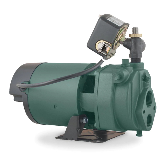
CONVERTIBLE JET PUMP
IL0345
Purchase Date
© 2020. All rights reserved.
INSTRUCTIONS
FOR DEEP WELL
INSTALLATION
1
CAST IRON
MODEL #1463-0006
(25-70 FT.)
024990 C
Publicidad
Tabla de contenido
Solución de problemas

Manuales relacionados para Zoeller 1463-0006


Resumen de contenidos para Zoeller 1463-0006
- Página 1 CAST IRON CONVERTIBLE JET PUMP ZoellerAtHome.com MODEL #1463-0006 Zoeller is a registered trademark of ® Zoeller Co. All Rights Reserved. INSTRUCTIONS FOR DEEP WELL INSTALLATION (25-70 FT.) IL0345 ATTACH YOUR RECEIPT HERE Purchase Date Serial Number Questions, problems, missing parts? Before returning to your retailer, call our customer service department at 1-800-584-8089, 7:30 a.m.
-
Página 2: Product Specifications
HP VOLTAGE HZ ROTOR DEEP WELL AMPS AMPS 30 FT 40 FT 50 FT 60 FT 70 FT 1463-0006 115/230 14/7 52/26 10.6 SAFETY INFORMATION Please read and understand this entire manual before attempting to assemble, operate, or install the product. -
Página 3: Package Contents
Unit must be securely and adequately electrically grounded. This can be accomplished by wiring the unit to a ground metal-clad raceway system or by using a separate ground wire connected to the bare metal of the motor frame or other suitable means. •... - Página 4 PREPARATION Before beginning installation of product, make sure all parts are present. If any part is missing or damaged, do not attempt to assemble the product. Compare parts to package contents list. Estimated Installation Time: 2 hours. Tools Required for New Installation (not included): pipe wrenches (2), wire strippers, needle-nose pliers, Phillips screwdriver, wire cutters, adjustable wrench, 2-step PVC glue system (primer and sealer), thread tape, tire gauge and tire pump Parts Required for New Installation (not included): 1-1/4 In.
- Página 5 Typical Pump Setup Discharge to Home 1-1/4 in. 3/4 in. Suction Discharge Pipe 1. Deep wells (25 - 70 ft. lift) where well ID is 4” or Pipe Suction more and a two pipe ejector is installed in the well. Lift (FOR WELL DEPTHS OF 0-25 FT., SEE 1 in.
- Página 6 3. All piping from the well to the pump should slope slightly upward with no sagging. Support suction Unions pipe between water source and pump. Unions in Suction Lift the suction line near the pump and well will aid in servicing.
- Página 7 PUMP TO PRESSURE TANK CONNECTION (DISCHARGE PIPE) - DEEP WELL 1. To begin the connection to the pressure tank, install the 1 in x 3/4 in adapter (included) to pump Flow Control discharge. Install flow control body to adapter. Screw Control Using Teflon tape, position the discharge outlet of Body...
- Página 8 5. Continue with fittings and pipe to the pressure tank. A 3/4 in. union is optional but recommended for easy connection and disconnection. CAUTION: Install a pressure relief valve on any installation where the pump pressure can exceed the maximum working pressure of the tank and plumbing.
-
Página 9: Shut Off Valve
4. Install a 3/4 in. union (optional) and continue with pipe and 3/4 in. x 3/4 in. x 3/4 in. tee. Glue Union IL1368 5. Make the connection to the house plumbing. From the tee, install pipe and shut off valve (optional). - Página 10 PUMP ELECTRICAL CONNECTIONS WIRING DIAGRAM WARNING: Check Voltage of Power Source • Always disconnect pump from electricity before Before Connecting 115 Volts 230 Volts performing any work on the motor. Single Phase Single Phase Line Line • Under-sized wiring can cause motor failure and even fire.
- Página 11 2. Insert an electrical wire strain relief into the opening in the side of the pressure switch closest to the motor. IL1372 3. Thread the cable from the pump motor through the strain relief into the pressure switch cavity Wire from motor and tighten both screws on the strain relief.
- Página 12 6. Insert an electrical wire strain relief into the opening in the opposite side of the pressure Wire from switch. motor Strain relief Pressure switch IL1376 7. Thread the cable from the power supply through Wire from Wire from the strain relief and tighten both screws on the power motor strain relief.
- Página 13 starwatersystems.com UL Std. No. 778 ENCLOSURE 3 JHU10 Pump: Rev: 98U1071 Motor: To change from 230 V to 115 V Volts 115/230 S.F. Amps 14/7 1. The motor of this pump is dual voltage and can S.F. Amps: 14/7 3450 Type Cont.
- Página 14 PUMP PRIMING & STARTUP - DEEP WELL CAUTION: All pumps must be primed (filling the cavity with water) before they are first operated. This may take several gallons of water, as the suction line will be filled in addition to the pump cavity. 1.
- Página 15 5. If pump is correctly primed, pressure will quickly build and register on the gauge mounted on the pump body. If pressure does not build, repeat priming operation. All air must be vented from the drive and suction pipes, as well as the body before the pump will prime.
-
Página 16: Care And Maintenance
CARE AND MAINTENANCE Winterizing PREVENT CAUTION: Drain the entire system if there is PUMP danger of freezing. A drain plug is provided at the DAMAGE! bottom of the pump for this purpose. Remove plug in freezing weather IL0345 © 2020. All rights reserved. - Página 17 QUICK TROUBLE-SHOOTING CHECKLIST Please review the following troubleshooting questions before returning a pump as defective. If you have any questions, please call Customer Service at (800) 584-8089. 1. Check date code to make sure pump is within warranty period. Date code is the month and MODEL LIQUID PUMP LR90197...
-
Página 18: Troubleshooting
TROUBLESHOOTING PROBLEM POSSIBLE CAUSE CORRECTIVE ACTION Little or no 1. Casing not initially filled with water 1. Fill pump casing discharge 2. Suction lift too high, or too long 2. Move pump closer to water source 3. Hole or air leak in suction line 3. -
Página 19: Repair Parts
WARRANTY This product is warranted for two years from the date of purchase. Subject to the conditions hereinafter set forth, the manufacturer will repair or replace to the original consumer any portion of the product which proves defective due to defective materials or workmanship. To obtain warranty service, contact the dealer from whom the product was purchased. - Página 20 HIERRO FUNDIDO BOMBA CONVERTIBLES ZoellerAtHome.com DE JET MODELO #1463-0006 Zoeller es una marca registrada de ® Zoeller Co. INSTRUCCIONES Todos derechos reservados. PARA INSTALACIONES DE POZO PROFUNDO 7.6-27.4 M (25-90 PIES) IL0345 ADJUNTE SU RECIBO AQUÍ Número de serie Fecha de compra ¿Preguntas, problemas, partes faltantes? Antes de acudir al minorista, llame a nuestro departamento...
-
Página 21: Especificaciones Del Producto
POZOS PROFUNDOS ARTÍCULO AMPERAJE VOLTAJE DEL ROTOR MÁXIMO 12,2 15,2 18,3 21,3 BLOQUEADO 1463-0006 115/230 14/7 52/26 40,1 29,9 27,6 21,6 17,4 INFORMACIÓN DE SEGURIDAD Lea y comprenda todo el manual antes de intentar ensamblar, operar o instalar el producto. -
Página 22: Contenido Del Paquete
funcionar a 115 V o 230 V. Viene preconfigurada de fábrica para funcionar a 230 V. • ALERTA DE DESCARGA ELÉCTRICA. La unidad debe estar conectada a tierra de forma segura y adecuada. Esto se puede hacer cableando la unidad a un sistema de conductos individuales con recubrimiento metálico y conexión a tierra o utilizando un cable de conexión a tierra por separado conectado a la parte metálica al descubierto del armazón del motor o de otra manera adecuada. -
Página 23: Preparación
PREPARACIÓN Antes de comenzar a instalar el producto, asegúrese de tener todas las piezas. No intente ensamblar el producto si falta alguna pieza o si estas están dañadas. Compare las piezas con la lista del contenido del paquete. Tiempo estimado de instalación: 2 horas. Herramientas necesarias para instalaciones nuevas: llave para tuberías (2), pelacables, pinzas de punta de aguja, destornillador Phillips, cortadores de cables, llave ajustable, sistema para pegar PVC de 2 pasos (imprimante y sellador), cinta para roscas, medidor de y bomba para neumáticos... -
Página 24: Configuración Típica De La Bomba
Configuración típica de la bomba Tubería de Descarga hacia la casa succión 1-1/4 pulg. 3/4 pulg. tubería de descarga 1. Pozos profundos (con 7.6-7.4 m [25-90 pies] de Extracción de agua extracción) donde el diámetro interno del pozo es de 10.2 cm (4 pulg.) o más y hay un eyector de Tubería de tubería doble instalado en el pozo. -
Página 25: Conexión Desde El Pozo A La Bomba (Tubería De Succión) - Para Pozos Profundos
2. Revise la tubería y la válvula de zapata en busca de fugas llenando las tuberías de agua. La pérdida continua de agua indica una fuga en la tubería, en la válvula de zapata o en las uniones y debe corregirse. Si no se encuentran fugas, proceda con la Eyector CONEXIÓN DEL POZO A LA BOMBA (TUBERÍA DE... -
Página 26: Conexión De La Bomba Al Tanque De Presión (Tubería De Descarga) - Pozo Profundo
2. Complete la conexión del pozo con las tuberías y los conectores adicionales según sea necesario. CONEXIÓN DE LA BOMBA AL TANQUE DE PRESIÓN (TUBERÍA DE DESCARGA) - POZO PROFUNDO 1. Para empezar la conexión al tanque de presión, ensamble sin apretar la unidad de control de flujo Tornillo de a la cabeza de la bomba. -
Página 27: Conexión Del Tanque A La Casa
4. Instale un manómetro opcional en la rosca de 1/4 pulg. en el costado del cuerpo de la bomba. La cara del manómetro debería colocarse de manera que el medidor pueda leerse con facilidad. IL1391 5. Continúe con los conectores y la tubería hacía al tanque de presión. -
Página 28: Válvula De Cierre
2. Instale un codo de 2.5 cm (1 pulg.). Codo IL1366 Cola 3. Fije una unión deslizante de 2.5 cm (1 pulg.) (con cola) x un adaptador de rosca hembra de 1.9 cm (3/4 pulg.) y uno de rosca macho de 1.9 Acoplamiento cm (3/4 pulg.) x una unión deslizante de 1.9 cm (3/4 pulg.). -
Página 29: Conexiones Eléctricas De La Bomba
6. Se muestra la instalación completa en un pozo profundo con las tuberías y el tanque. IL1386 CONEXIONES ELÉCTRICAS DE LA BOMBA ADVERTENCIA: DIAGRAMA DE CABLEADO Verifique el voltaje de la fuente de • Siempre desconecte la bomba de la fuente de alimentación antes de conectarlo 115 voltios 230 voltios... - Página 30 Cableado del interruptor de presión: PRECAUCIÓN: Asegúrese de que la fuente de alimentación cumpla con los requisitos de la bomba. Esta bomba tiene un motor de voltaje doble y puede funcionar con 115 voltios o 230 voltios. La bomba viene preconfigurada de fábrica para funcionar a 230 V.
-
Página 31: Cable Desde El Suministro De Electricidad
4. Conecte los dos hilos del cable del motor a los dos terminales interiores del presostato. Cable desde el motor IL1374 5. Conecte el hilo verde de tierra del cable del motor a uno de los tornillos verdes de tierra en la parte inferior del presostato. - Página 32 8. Conecte los dos hilos de la fuente de alimentación a los dos terminales exteriores del presostato. Cable desde el suministro de electricidad Dos cables Cable desde el desde el suministro de motor electricidad Terminal Terminal exterior exterior 9. Conecte el hilo verde de tierra de la fuente Tornillos de puesta a tierra de alimentación a uno de los tornillos verdes de tierra restantes en el presostato y vuelva a...
-
Página 33: Cebado Y Puesta En Marcha De La Bomba - Pozo Profundo
b. Jale el cable rojo con el conector de bandera 115 V hembra del terminal “B”. Colóquelo a la derecha en el poste de paleta del terminal L2. ROJO GRIS ROJO GRIS 115 V c. Vuelva a instalar la cubierta posterior del motor. - Página 34 3. La válvula de control de flujo le permite ajustar el equilibrio entre la presión del cuerpo de la bomba y la presión del hogar. Instale un manómetro en el cuerpo de la bomba y un segundo manómetro en la línea de descarga.Siga los pasos a continuación Manómetro- para maximizar la presión en su hogar mientras se Presión...
-
Página 35: Cuidado Y Mantenimiento
IMPORTANTE: Si la bomba no se ceba en los Uniones siguientes cinco minutos: Elevación por succión Desconecte la energía en la caja de disyuntores y compruebe todas las conexiones de tuberías en busca de fugas. Todas las conexiones deben ser herméticas y evitar el paso del agua y aire para que Soporte la bomba pueda funcionar. -
Página 36: Lista De Verificación Rápida Para Solución De Problemas
LISTA DE VERIFICACIÓN RÁPIDA PARA SOLUCIÓN DE PROBLEMAS Revise las siguientes preguntas de solución de problemas antes de devolver una bomba como defectuosa. Si tiene alguna pregunta, llame a Servicio al Cliente al (800) 584-8089. 1. Check the warranty listed in the instructions to make sure the pump meets warranty MODEL LIQUID PUMP... -
Página 37: Solución De Problemas
SOLUCIÓN DE PROBLEMAS PROBLEMA CAUSA POSIBLE ACCIÓN CORRECTIVA La descarga 1. El entubado no está inicialmente relleno con 1. Llene el entubado de la bomba es mínima agua o no hay 2. La elevación de succión es demasiado alta o 2. -
Página 38: Garantía
GARANTÍA Este producto se garantiza por dos años a partir de la fecha de compra. Sujeto a las condiciones indicadas a continuación, el fabricante se compromete a reparar o reemplazar al consumidor original cualquier parte del producto que resulte defectuosa debido a defectos de materiales o mano de obra. Para obtener el servicio de garantía, póngase en contacto con el distribuidor al que le compró... - Página 39 CAST IRON CONVERTIBLE JET PUMP ZoellerAtHome.com MODEL #1463-0006 Español p. 19 Zoeller is a registered trademark of ® Zoeller Co. All Rights Reserved. INSTRUCTIONS FOR SHALLOW WELL INSTALLATION (0-25 FT.) IL0194 ATTACH YOUR RECEIPT HERE Purchase Date Serial Number Questions, problems, missing parts? Before returning to your retailer, call our customer service department at 1-800-584-8089, 7:30 a.m.
- Página 40 ITEM # HP VOLTAGE HZ ROTOR AMPS SHALLOW WELL AMPS 5 FT 15 FT 25 FT 1463-0006 115/230 14/7 52/26 10.4 SAFETY INFORMATION Please read and understand this entire manual before attempting to assemble, operate, or install the product. •...
- Página 41 Unit must be securely and adequately electrically grounded. This can be accomplished by wiring the unit to a ground metal-clad raceway system or by using a separate ground wire connected to the bare metal of the motor frame or other suitable means. •...
- Página 42 PREPARATION Before beginning installation of product, make sure all parts are present. If any part is missing or damaged, do not attempt to assemble the product. Compare parts to package contents list. Estimated Installation Time: 2 hours. Tools Required for New Installation (not included): pipe wrenches (2), wire strippers, needle-nose pliers, Phillips screwdriver, wire cutters, adjustable wrench, 2-step PVC glue system (primer and sealer), thread tape, tire gauge and tire pump.
- Página 43 Typical Pump Setup 3/4 in. Discharge Pipe Discharge to Home Thconvertible jet pump is designed for use in these Suction applications: Lift 1. Shallow wells (0 - 25 ft. lift) where ejector bolts to 1-1/4 in. pump. Suction Pipe (FOR WELL DEPTHS OVER 25 FT., SEE 25 ft.
- Página 44 WELL TO PUMP CONNECTION (SUCTION PIPE) - SHALLOW WELL 1. Attach ejector to face of pump with two (2) bolts and gasket provided. Venturi tube on the ejector inserts into the top tapping of the face of the pump Venturi Ejector Tube 2.
- Página 45 4. Finish the connection to your well with additional Union pipe and fittings as needed. Slope pipe upward Pipe support Water level Foot valve IL2134 PUMP TO PRESSURE TANK CONNECTION (DISCHARGE PIPE)-SHALLOW WELL 1. Begin the connection to the pressure tank. Install a 1 in.
- Página 46 4. Continue with fittings and pipe to the pressure tank. A 3/4 in. union (optional) is recommended Glue for easy connection and disconnection. TANK TO HOUSE CONNECTION 1. Most pressure tanks will have a 1 inch inlet elbow on the bottom. Connect to this elbow with a 1 in. MPT x 1 in.
- Página 47 4. Install a 3/4 in. union (optional) and continue with pipe and 3/4 in. x 3/4 in. x 3/4 in. tee. Glue Union IL1368 5. Make the connection to the house plumbing. From the tee, install pipe and shut off valve (optional).
- Página 48 PUMP ELECTRICAL CONNECTIONS WIRING DIAGRAM WARNING: Check Voltage of Power Source • Always disconnect pump from electricity before Before Connecting 115 Volts 230 Volts performing any work on the motor. Single Phase Single Phase Line Line • Under-sized wiring can cause motor failure and even fire.
- Página 49 2. Insert an electrical wire strain relief into the opening in the side of the pressure switch closest to the motor. IL1372 3. Thread the cable from the pump motor through the strain relief into the pressure switch cavity Wire from motor and tighten both screws on the strain relief.
- Página 50 6. Insert an electrical wire strain relief into the opening in the opposite side of the pressure Wire from switch. motor Strain relief Pressure switch IL1376 7. Thread the cable from the power supply through Wire from Wire from the strain relief and tighten both screws on the power motor strain relief.
- Página 51 starwatersystems.com UL Std. No. 778 ENCLOSURE 3 JHU10 Pump: Rev: 98U1071 Motor: To change from 230 V to 115 V Volts 115/230 S.F. Amps 14/7 1. The motor of this pump is dual voltage and can S.F. Amps: 14/7 3450 Type Cont.
- Página 52 PUMP PRIMING & STARTUP - SHALLOW WELL CAUTION: All pumps must be primed (filling the cavity with water) before they are first operated. Priming plug with pressure This may take several gallons of water, as the gauge suction line will be filled in addition to the pump cavity.
- Página 53 5. Thread in priming plug and then open optional ball valve if installed by turning handle to line up with the pipe. IL2145 6. Turn on breaker to start pump. Breaker Box IMPORTANT: If the pump fails to prime within five minutes: Turn power off at the breaker box and check all pipe connections for leaks.
- Página 54 QUICK TROUBLE-SHOOTING CHECKLIST Please review the following troubleshooting questions before returning a pump as defective. If you have any questions, please call Customer Service at (800) 584-8089. 1. Check date code to make sure pump is within warranty period. Date code is the month and MODEL LIQUID PUMP LR90197...
- Página 55 TROUBLESHOOTING PROBLEM POSSIBLE CAUSE CORRECTIVE ACTION Little or no 1. Casing not initially filled with water 1. Fill pump casing discharge 2. Suction lift too high, or too long 2. Move pump closer to water source 3. Hole or air leak in suction line 3.
- Página 56 WARRANTY This product is warranted for two years from the date of purchase. Subject to the conditions hereinafter set forth, the manufacturer will repair or replace to the original consumer any portion of the product which proves defective due to defective materials or workmanship. To obtain warranty service, contact the dealer from whom the product was purchased.
- Página 57 HIERRO FUNDIDO BOMBA CONVERTIBLES ZoellerAtHome.com DE JET MODELO #1463-0006 Zoeller es una marca registrada de ® Zoeller Co. INSTRUCCIONES Todos derechos reservados. PARA INSTALACIONES DE POZO POCO PROFUNDO DE 0-7.6 M (0-25 PIES) IL0194 ADJUNTE SU RECIBO AQUÍ Número de serie Fecha de compra ¿Preguntas, problemas, partes faltantes? Antes de acudir al minorista, llame a nuestro departamento...
- Página 58 VOLTAJE DEL ROTOR POZO DE POCA PROFUNDIDAD MÁXIMO BLOQUEADO 1.5 M 4.6 M 7.6 M 1463-0006 115/230 14/7 52/26 39,4 28,4 14,8 INFORMACIÓN DE SEGURIDAD Lea y comprenda todo el manual antes de intentar ensamblar, operar o instalar el producto.
- Página 59 funcionar a 115 V o 230 V. Viene preconfigurada de fábrica para funcionar a 230 V. • ALERTA DE DESCARGA ELÉCTRICA. La unidad debe estar conectada a tierra de forma segura y adecuada. Esto se puede hacer cableando la unidad a un sistema de conductos individuales con recubrimiento metálico y conexión a tierra o utilizando un cable de conexión a tierra por separado conectado a la parte metálica al descubierto del armazón del motor o de otra manera adecuada.
- Página 60 PREPARACIÓN Antes de comenzar a instalar el producto, asegúrese de tener todas las piezas. No intente ensamblar el producto si falta alguna pieza o si estas están dañadas. Compare las piezas con la lista del contenido del paquete. Tiempo estimado de instalación: 2 horas. Herramientas necesarias para instalaciones nuevas: llave para tuberías (2), pelacables, pinzas de punta de aguja, destornillador Phillips, cortadores de cables, llave ajustable, sistema para pegar PVC de 2 pasos (imprimante y sellador), cinta para roscas, medidor de y bomba para neumáticos...
-
Página 61: Instalación De Tuberías En Un Pozo - Pozo Poco Profundo
Configuración típica de la bomba 3/4 pulg. tubería de descarga Descarga hacia la casa Esta bomba de chorro convertible está diseñada Extracción de agua para ser usada en las siguientes aplicaciones: 1. Pozos poco profundos (de 0 a 7,6 m [0 a 25 pies] 3,2 cm (1-1/4 pulg.) de extracción de agua) donde el eyector está... - Página 62 CONEXIÓN DESDE EL POZO A LA BOMBA (TUBERÍA DE SUCCIÓN) - POZOS DE POCA PROFUNDIDAD 1. Conecte el eyector a la superficie de la bomba con los dos pernos y el empaque proporcionados. Se pone el tubo venturi dentro de la abertura superior en la superficie de la bomba.
- Página 63 4. Complete la conexión del pozo con las tuberías y Unión los conectores adicionales según sea necesario. Incline el tubo hacia arriba Soporte de la tubería Nivel de agua Válvula de pie IL2134 CONEXIÓN DE LA BOMBA AL TANQUE DE PRESIÓN (TUBERÍA DE DESCARGA) - POZO POCO PROFUNDO 1.
- Página 64 4. Continúe con los conectores y la tubería hacía al tanque de presión. Use una unión de 1.9 cm Cola (3/4 pulg.) (opcional) para facilitar la conexión y desconexión. CONEXIÓN DEL TANQUE A LA CASA 1. La mayoría de los tanques de presión tendrán un codo de entrada de 2.5 cm (1 pulg.) en la parte inferior.
- Página 65 4. Instale una unión (opcional) de 1.9 cm (3/4 pulg.) y continúe con el tubo y la “T” de 1.9 x 1.9 “T” x 1.9 cm (3/4 x 3/4 x 3/4 pulg.). Cola Unión IL1368 5. Haga la conexión a la tubería de la casa. Desde la “T”, instale la tubería y la válvula de cierre (opcional).
-
Página 66: Cableado Del Interruptor De Presión
CONEXIONES ELÉCTRICAS DE LA BOMBA DIAGRAMA DE CABLEADO ADVERTENCIA: Verifique el voltaje de la fuente de • Siempre desconecte la bomba de la fuente de alimentación antes de conectarlo 115 voltios 230 voltios energía antes de llevar a cabo cualquier trabajo Fase única Fase única Línea... - Página 67 2. Inserte un pasacables de cables eléctricos en la abertura del lado del presostato más cercano al motor. IL1372 3. Pase el cable desde el motor de la bomba a través del pasacables hasta dentro la cavidad Cable desde el motor del presostato y apriete los dos tornillos del pasacables.
- Página 68 6. Inserte un pasacables de cables eléctricos en la abertura del lado opuesto del presostato. Cable desde el Aliviador motor tensión Interruptor de presión IL1376 7. Pase el cable desde la fuente de alimentación a través del pasacables y apriete los dos tornillos del pasacables.
- Página 69 LR90197 starwatersystems.com UL Std. No. 778 ENCLOSURE 3 JHU10 Pump: Rev: Para cambiar de 230 V a 115 V 98U1071 Motor: 1. El motor de esta bomba es de doble voltaje y Volts 115/230 S.F. Amps 14/7 puede funcionar a 115 V o 230 V. En general, es S.F.
-
Página 70: Cebado Y Puesta En Marcha De La Bomba - Pozo Poco Profundo
CEBADO Y PUESTA EN MARCHA DE LA BOMBA - POZO POCO PROFUNDO PRECAUCIÓN: Todas las bombas deben ser cebadas (llenar la cavidad con agua) antes de que Tapón de cebado con se operen por primera vez. Esto puede requerir manómetro varios litros de agua, ya que la línea de succión se llenará... -
Página 71: Caja De Interruptores
5. Enrosque el tapón de cebado y luego abra la válvula de bola opcional, si está instalada, girando la manija para alinearla con la tubería. IL2145 6. Encienda el interruptor para iniciar el funcionamiento de la bomba. Caja de interruptores IMPORTANTE: Si la bomba no se ceba en los siguientes cinco minutos: Desconecte la energía en la caja de disyuntores... - Página 72 LISTA DE VERIFICACIÓN RÁPIDA PARA SOLUCIÓN DE PROBLEMAS Revise las siguientes preguntas de solución de problemas antes de devolver una bomba como defectuosa. Si tiene alguna pregunta, llame a Servicio al Cliente al (800) 584-8089. 1. Verifique el código de fecha para asegurarse de que la bomba está...
- Página 73 SOLUCIÓN DE PROBLEMAS PROBLEMA CAUSA POSIBLE ACCIÓN CORRECTIVA La descarga 1. El entubado no está inicialmente relleno con 1. Llene el entubado de la bomba es mínima agua o no hay 2. La elevación de succión es demasiado alta o 2.
- Página 74 GARANTÍA Este producto se garantiza por dos años a partir de la fecha de compra. Sujeto a las condiciones indicadas a continuación, el fabricante se compromete a reparar o reemplazar al consumidor original cualquier parte del producto que resulte defectuosa debido a defectos de materiales o mano de obra. Para obtener el servicio de garantía, póngase en contacto con el distribuidor al que le compró...