Tabla de contenido
Publicidad
Idiomas disponibles
Idiomas disponibles
Enlaces rápidos
Publicidad
Tabla de contenido

Resumen de contenidos para KTM 62112935044
- Página 1 Information Power Parts 62112935044 04. 2011 3.211.754 *3211754* www.ktm.com...
- Página 2 Le rogamos seguir las instrucciones para el montaje. A fin de garantizar la máxima seguridad y un funcionamiento correcto es imprescindible acudir a un concesionario autorizado de KTM para obtener el mejor asesoramiento técnico e instalar correctamente las KTM PowerParts.
-
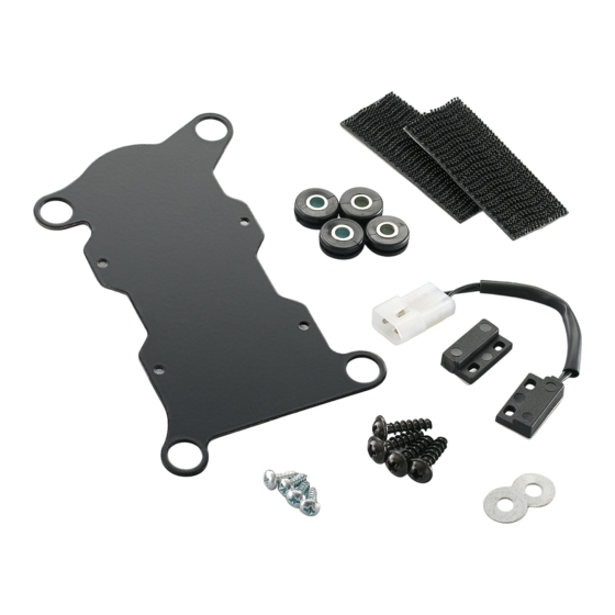
Página 3: Lieferumfang
Lieferumfang 1x Halteblech Alarmanlage 62512035050 4x Kabeltüllen 60012035160 4x Büchse 62512035070 4x PT-Schraube 0081500181 2x Druckverschluss 60112035010 1x Reedschalter 60012035185 4x LI.Blechschraube 3,5x10 0981350103 3x U-Scheibe DIN 9021 A 5,3 0021050003 1x Kabelbinder 44011076305 2x Zylinderschraube M4x20 0912040203 2x SS Mutter DIN985 M4 0985040003 Modelle ohne ABS Vorarbeiten... - Página 4 - Alarmanlage (1) mit dem Stecker (2) verbinden und mit der Gummiabdeckung sichern. Gummiabdeckung mit Kabelbinder an Position (3) sichern. Anschließend die Alarmanlage auf dem Halteblech fixieren. Modelle mit ABS Vorarbeiten - Sitzbank demontieren. - Gepäckträger (4) demontieren. - Hitzeschutz links (5) und rechts (6) demontieren. - Seitenteil links (7) und rechts (8) demontieren.
- Página 5 Befestigung Reedschalter (alle Modelle) - Reedschalter (1) auf Rahmenheck wie gezeigt am Sitzbankschloss anlegen und mittig am Träger aufkleben. - Reedschalter am Kabelstrang anschließen. HINWEIS: Zusätzlich kann der Reedschalter noch mit den LI.Blechschrauben DIN7981- 3,5X10 angeschraubt werden. Dazu Bohrungen markieren und mit einem D3 mm Bohrer vorbohren.
-
Página 6: Scope Of Delivery
Scope of delivery 1x retaining bracket, alarm system 62512035050 4x cable support sleeves 60012035160 4x bushes 62512035070 4x PT screws 0081500181 2x Velcro strips 60112035010 1x reed switch 60012035185 4x oval head tapping screws 3.5x10 0981350103 3x U washers DIN 9021 A 5.3 0021050003 1x cable binder 44011076305... - Página 7 - Connect the alarm system (1) with the connector (2) and secure with the rubber cover. Secure the rubber cover in position (3) using the cable bin- der. Then fix the alarm system onto the retaining bracket. Models with ABS Preparations - Remove the seat.
- Página 8 Fastening the reed switch (all models) - Position the reed switch (1) on the rear frame against the seat lock as shown and bond centrally onto the rack. - Connect the reed switch to the wiring harness. NOTE: In addition, the reed switch can be screwed into place with the oval head tapping screws DIN7981- 3.5X10.
-
Página 9: Ambito Della Fornitura
Ambito della fornitura N. 1 piastrina per l’impianto d’allarme 62512035050 N. 4 passacavi 60012035160 N. 4 bussole 62512035070 N. 4 viti PT 0081500181 N. 2 velcri 60112035010 N. 1 contatto Reed 60012035185 N. 4 viti autofilettanti con testa cilindrica 3,5x10 0981350103 N. -
Página 10: Operazioni Preliminari
- Collegare l’impianto d’allarme (1) con il connettore (2) e assicurarlo con il rivestimento in gomma. Con la fascetta serracavi fissare il rivestimento in gomma in posizione (3). Infine fissare l’impianto d’allarme alla piastrina. Modelli con ABS Operazioni preliminari - Smontare la sella. - Smontare il portapacchi (4). - Página 11 Fissaggio del contatto Reed (tutti i modelli) - Applicare il contatto Reed (1) sul telaietto posteriore in corrispondenza della serratura della sella (come mostrato) e incollarlo al centro del supporto. - Collegare il contatto Reed al cablaggio. NOTA: Il contatto Reed può essere ulteriormente assicurato con le viti autofilettanti a testa cilindrica DIN7981- 3,5X10.
- Página 12 Contenu de la livraison : 1 tôle de fixation pour alarme 62512035050 4 cache-câbles 60012035160 4 douilles 62512035070 4 vis PT 0081500181 2 bandes de fixation 60112035010 1 contacteur Reed 60012035185 4 vis à tôle LI 3,5x10 0981350103 3 rondelles en U DIN 9021 A 5,3 0021050003 1 serre-câble 44011076305...
- Página 13 - Raccorder l’alarme (1) au connecteur (2) et bloquer avec le cache en caout- chouc. Bloquer le cache en caoutchouc avec le serre-câble en position (3). Fixer ensuite l’alarme sur la tôle de fixation. Modèles avec ABS Travaux préalables - Démonter la selle. - Démonter le porte-bagages (4).
-
Página 14: Montage Final
Fixation du contacteur Reed (tous les modèles) - Poser le contacteur Reed (1) sur l’arrière du cadre comme indiqué sur la serrure de selle et le coller au centre du cadre. - Raccorder le contacteur Reed au faisceau de câbles. REMARQUE : Le contacteur Reed peut également être vissé... -
Página 15: Volumen De Suministro
Volumen de suministro 1x chapa de sujeción para el equipo de alarma 62512035050 4x manguitos para cables 60012035160 4x casquillos 62512035070 4x tornillos PT 0081500181 2x cierres a presión 60112035010 1x interruptor de lengüeta 60012035185 4x tornillos roscachapa 3,5x10 0981350103 3x arandelas en U DIN 9021 A 5,3 0021050003 1x cinta sujetacables... - Página 16 - Conectar el conector (2) al equipo de alarma (1) y asegurarlo con la cubierta de goma. Asegurar la cubierta de goma con cinta sujetacables en la posi- ción (3). Acto seguido, fijar el equipo de alarma a la chapa de sujeción. Modelos con ABS Trabajos previos - Desmontar el asiento.
- Página 17 Fijación del interruptor de lengüeta (todos los modelos) - Colocar el interruptor de lengüeta (1) en el cierre del asiento del subcha- sis y pegarlo centrado en el soporte. - Conectar el interruptor de lengüeta al ramal de cables. ADVERTENCIA: Adicionalmente, el interruptor de lengüeta también se puede atornillar con los tornillos roscachapa DIN7981- 3,5X10.


