Tabla de contenido
Publicidad
Idiomas disponibles
Idiomas disponibles
Enlaces rápidos
BEST BY BROAN P.O. Box 140, Hartford, WI 53027
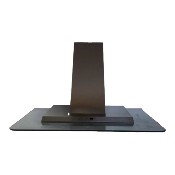
Model WC26E
For use with Best By Broan Exterior
Blower model EB6, EB9, EB12 and EB15;
Or In-Line Blower model ILB3, ILB6, ILB9 or ILB11
ENGLISH.....................................2
FRANÇAIS................................15
ESPAÑOL..................................28
99043778B
Publicidad
Tabla de contenido

Manuales relacionados para Broan Best WC26E


Resumen de contenidos para Broan Best WC26E
- Página 1 Model WC26E For use with Best By Broan Exterior Blower model EB6, EB9, EB12 and EB15; Or In-Line Blower model ILB3, ILB6, ILB9 or ILB11 ENGLISH........2 FRANÇAIS........15 ESPAÑOL........28 99043778B BEST BY BROAN P.O. Box 140, Hartford, WI 53027...
- Página 2 READ AND SAVE THESE INSTRUCTIONS INTENDED FOR DOMESTIC COOKING ONLY WARNING TO REDUCE THE RISK OF FIRE, ELECTRIC SHOCK, OR INJURY TO PERSONS, OBSERVE THE FOLLOWING: 1. Use this unit only in the manner intended by the manufacturer. If you have questions, contact the manufacturer at the address or telephone number listed in the warranty.
- Página 3 10. Use with approved cord-connection kit only. 11. Please read specification label on product for further information and requirements. For use with Best by Broan Exterior Blower model EB6, EB9, EB12 and EB15; Or In-Line Blower model ILB3, ILB6, ILB9 or ILB11...
- Página 4 OPERATION Controls The hood is operated using the (5) push buttons located on the front edge of the hood. The Light switch turns the halogen lights on and off. Push the light switch once to turn the lights ON - push a second time to turn the lights ON to a brighter level - push a third time to turn the lights OFF.
-
Página 5: Fuse Replacement
HALOGEN BULBS This range hood requires two halogen bulbs (Type T3, 12Volt, 20Watt Max, G-4 Base). WARNING: Always switch off the elec- trical supply before carrying out any op- eration on the appliance. To change bulbs: 1. Open the cover by prying from the proper slots. - Página 6 MAINTENANCE Proper maintenance of the Range Hood will assure proper performance of the unit. Grease Filter The grease filter should be cleaned frequently. Use a warm detergent solution. Grease filter is dishwasher safe. See “INSTALL FILTERS” section for removal and installation instructions. Hood Cleaning Stainless steel is one of the easiest materials to keep clean.
-
Página 7: Prepare The Hood
PREPARE THE HOOD Unpack hood and check contents. You should receive: 1 - Hood 1 - Decorative Flue Assembly 1 - Parts Bag (B080810747) containing: 1 - Mounting Bracket 1 - Discharge Collar 1 - Flue Mounting Bracket 8 - Mounting Screws (4.8 x 38mm Pan Head) 6 - Mounting Screws (3.9 x 9.5mm Pan Head) 2 - Mounting Screws (3.9 x 6mm Flat Head) 8 - Drywall Anchors... - Página 8 EXTERIOR OR INLINE BLOWER SELECTION CAUTION: To reduce the risk of fire and electric shock, install this rangehood only with EB6, EB9, EB12 or EB15 Exterior Blowers, or In-Line Blower model ILB3, ILB6, ILB9 or ILB11. The blower must be UL listed for Canadian and U.S. use, and evaluated for use with solid state speed control, rated 120V, 60 Hz, 6.0 A max.
- Página 9 WIRING BLOWER CONNECTION AT HOOD CAUTION: All electrical wiring should Exterior or be done by a qualified person (s) in In-Line blower accordance with all applicable codes and CONNECT: WHITE-TO-WHITE, standards. This range hood must be RED-TO-BLACK, properly grounded. GREEN-TO-GROUND. Do not turn power on at service panel until all wires have been connected.
- Página 10 INSTALL MOUNTING FRAMING BEHIND BRACKET WOOD CROSS SUPPORT 1. Construct wood wall framing that is flush with interior surface of wall studs. Fig. 9. Make sure: a) the framing is centered over installation location. b) the height of the framing will allow the mounting bracket to be secured to the framing within the dimensions shown.
- Página 11 INSTALL FLUE MOUNTING FLUE MOUNTING BRACKET BRACKET 3.9 x 6 mm FLAT HEAD BRACKET SCREWS 1. Assemble the flue mounting bracket, adjusting outside width as shown. Fig.10 2. Carefully center the mounting bracket directly over the range hood location. 3. Secure the bracket assembly to the ceiling using (2) 4.8x38mm mounting screws 9-13/16”...
-
Página 12: Install The Hood
INSTALL THE HOOD Note: On stainless steel hoods, carefully remove the plastic protective film from all exterior surfaces of the hood and decorative flues, prior to final installation. Note: at least two people will be required to mount the hood. 1. - Página 13 INSTALL THE HOOD, cont’d 7. Carefully place the decorative flue on the hood. Fig. 14. UPPER ROOMS WITH 10-FOOT CEILINGS FLUE Rooms with 10-foot ceilings require flue ex- tension model AEWC26xB, available from your local dealer. 8. Discard the upper flue supplied with the product.
-
Página 14: Install Filters
EXPRESS OR IMPLIED, INCLUDING, BUT NOT LIMITED TO, IMPLIED WARRANTIES OR MERCHANT ABILITY OR FITNESS FOR A PARTICULAR PURPOSE. During this one-year period, Broan will, at its option, repair or replace, without charge, any product or part which is found to be defective under normal use and service. -
Página 15: Avertissements
LISEZ ET CONSERVEZ CES INSTRUCTIONS SEULEMENT POUR UTILISATION DOMESTIQUE AVERTISSEMENTS POUR REDUIRE LES RISQUES D’INCENDIE, DE DECHARGES ELECTRIQUES OU DE DOMMAGES AUX PERSONNES, OBSERVEZ LES INSTRUCTIONS SUIVANTES: 1. N’utilisez cet appareil que comme cela est indiqué par le constructeur. Si vous avez des problèmes, contactez le fabriquant à... - Página 16 11. Nous vous recommandons de lire l’étiquette indiquant les caractéristiques de votre hotte pour de plus amples informations et exigences. S’utilise avec unité extérieure Best by Broan, modèle EB6, EB9, EB12 et EB15; Ou unité In-Line, modèle ILB3, ILB6, ILB9 or ILB11...
- Página 17 FONCTIONNEMENT Commandes La hotte fonctionne à l’aide de cinq (5) boutons-poussoirs situés sur le bord antérieur de votre hotte. Le Bouton de la lumière allume et éteint les lampes halogènes. En pressant 1 fois la touche, la lumière s’allume au 1 niveau;...
-
Página 18: Remplacement Fusible
AMPOULES HALOGENES Ce modèle de hotte veut deux (2) ampoules halogènes (Type T3, 12Volt, 20 Watt Max, G- 4 Base). ATTENTION: avant de procéder à quelconque opération, débranchez l’appareil. Pour changer les ampoules: 1. Ouvrez le couvercle en faisant levier grâce aux fissures prévues à... - Página 19 ENTRETIEN Un bon entretien de votre hotte garantira une excellente performance. Filtre anti-graisse Le filtre anti-graisse doit être nettoyé fréquemment. Utilisez une solution contenant un détergent tiède. Le filtre anti-graisse peut être lavé au lave-vaisselle. Voir la section “INSTALLER LES FILTRES” pour les instructions relatives au démontage et à...
- Página 20 PREPAREZ LA HOTTE Enlever la hotte dans l’emballage et controller le contenu. Vous devez recevoir : 1 - Hotte 1 - Conduit décoratif 1 - Sachet (B080810747) avec: 1 - Étrier d’assemblage 1 - Collier d’évacuation 1 - Étrier de support 8 - Vis d’assemblage (4.8 x 38mm Tête ronde) 6 - Vis d’assemblage (3.9 x 9.5mm Tête ronde) 2 - Vis d’assemblage (3.9 x 6 mm Tête plate)
- Página 21 SELECTION UNITE EXTERIEURE OU INLINE ATTENTION : pour diminuer les risques d’incendie ou de décharges électriques, installer cette hotte uniquement avec des unité extérieures modèle EB6, EB9, EB12 ou EB15, ou unité In-Line modèle ILB3, ILB6, ILB9 ou ILB11. Les unités doivent être compries dans la liste UL pour l’utilisation au Canada et aux USA et approuvée pour l’utilisation avec un “dispositif de contrôle de la vitesse”...
-
Página 22: Installation Electrique
INSTALLATION ELECTRIQUE BRANCHEMENT DE LA TURBINE DE VENTILATION À LA HOTTE A T T E N T I O N : L ’ i n s t a l l a t i o n Unité extérieure BRANCHER:LE ou In-Line BLANC AVEC électrique doit être faite par du per- LE BLANC, LE... - Página 23 INSTALLATION ETRIER CADRE DERRIÈRE D’ASSEMBLAGE L’APPUI TRANSVERSAL EN BOIS 1. Construisez un cadre en bois pour le mur dont les vis-pivot ne dépassent pas. Fig. 9. Assurez-vous: a) que le cadre est centré au-dessus de l’emplacement de l’installation. b) la hauteur du cadre permettra que l’étrier d’assemblage soit fixé...
- Página 24 INSTALLATION ETRIER DE ETRIER DE 3.9 x 6 mm VIS SUPPORT DU CONDUIT SUPPORT DU D’ASSEMBLAGE À CONDUIT TÊTE PLATE DECORATIF DECORATIF Assemblez l’étrier de support du conduit décoratif en réglant la largeur extérieure comme indiqué. Fig. 10. Centrez soigneusement le support directement sur l’emplacement destine 9-13/16”...
-
Página 25: Installation De La Hotte
INSTALLATION DE LA HOTTE Remarque : si la hotte est en acier inoxydable, retirez précautionneusement le film protecteur des surfaces extérieures et du conduit décoratif avant de terminer l’installation. Remarque : la hotte doit être installée par au moins deux personnes. Soulevez la hotte et placez-la à... - Página 26 INSTALLATION DE LA HOTTE, suite 7. Placez précautionneusement le conduit CONDUIT décoratif sur la hotte (Fig. 14). SUPÉRIEUR PIÈCES AVEC DES PLAFONDS DE 10’ Les pièces avec des plafonds de 10’ ont besoin d’un modèle d’extension de conduit AEWC26xB, disponible auprès de votre distributeur local.
- Página 27 Cette garantie ne couvre pas (a) l’entretien normal ni (b) tout article ou toute pièce qui aient subi une utilisation erronée, une négligence, un accident, un entretien erroné ou une réparation (autre que de la part de Broan), une installation défectueuse ou bien une installation ne respectant pas les instructions d’installation recommandées.
- Página 28 LEA Y CONSERVE ESTAS INSTRUCCIONES INDICADO PARA EL USO EN COCINAS DOMESTICAS ADVERTENCIA PARA EVITAR EL RIESGO DE INCENDIO, CORTOCIRCUITO O DAÑO PARA LAS PERSONAS, OBSERVE ATENTAMENTE LAS SIGUIENTES NORMAS: 1. Use esta unidad solamente de la manera indicada por el fabricante; si tiene dudas, póngase en contacto con éste a la dirección o teléfono indicados en la garantía.
- Página 29 10. Use solamente con juego de conexión para alimentación aprobado. 11. Se recomienda leer la placa de caracteristicas del producto para ulterior información. Para uso con centralita externa Best by Broan, modelo EB6, EB9, EB12 y EB15; O centralita In-Line, modelo ILB3, ILB6, ILB9 o ILB11...
-
Página 30: Funcionamiento
FUNCIONAMIENTO Mandos La campana se opera mediante los 5 botones pulsadores que se encuentran el frontal de la campana. El interruptor luz enciende y apaga las lámparas halógenas. Pulsando el botón una vez, la luz se enciende a intensidad 1, pulsándolo una segunda vez, la luz se enciende a intensidad 2 (luz más intensa) y, pulsándolo otra vez más, la luz se apaga completamente. -
Página 31: Lamparas Halogenas
LAMPARAS HALOGENAS Este tipo de campana necesita dos (2) lámparas halógenas (Tipo T3, 12Volt, 20 Watt Max, G-4 Base). ATENCIÓN: antes de proceder a cualquier operación, es necesario desco- nectar el aparato. Para cambiar las lámparas: 1. Abra la tapa haciendo palanca sobre las hendiduras apropiadas. -
Página 32: Mantenimiento
MANTENIMIENTO Un mantenimiento adecuado de la campana asegura el funcionamiento correcto del aparato. Filtro antigrasa El filtro antigrasa debe limpiarse con frecuencia. Use un detergente que no sea fuerte.Use un detergente que no sea fuerte. El filtro antigrasa se puede meter en el lavavajillas. -
Página 33: Prepare La Campana
PREPARE LA CAMPANA Sacar la campana de l’embalaje y controlar el contenido. Recivireis: 1 - Campana 1 - Tubo decorativo 1 - Bolsita (B080810747) con: 1 - Soporte de montaje 1 - Casquillo 1 - Soporte para el montaje del tubo 8 - Tornillos de montaje (4.8x38mm cabeza redonda) 6 - Tornillos de montaje (3.9x9.5mm cabeza redonda) 2 - Tornillos de montaje (3.9x6 mm cabeza plano) -
Página 34: Selección De La Centralita Externa O Inline
SELECCIÓN DE LA CENTRALITA EXTERNA O INLINE ATENCIÓN: para reducir el riesgo de incendio o de descargas eléctricas, instale esta campana sólo con centralita externa mod. EB6, EB9, EB12 o EB15, o centralita In-Line mod. ILB3, ILB6, ILB9 o ILB11. La centralita tiene que estar incluida en la lista UL para el uso en Canadá... -
Página 35: Instalacion Electrica
INSTALACION ELECTRICA CONEXIÓN DEL VENTILADOR A LA CAMPANA PRECAUCIÓN : Toda la instalación Centralita externa o eléctrica tiene realizada CONECTE: EL CABLO BLANCO In-Line exclusivamente por personal preparado y a CON EL BLANCO, norma con los estándares y las reglas EL ROJO CON EL establecidas. -
Página 36: Instalacion Soporte De Montaje
INSTALACION SOPORTE DE MARCO POSTERIOR DEL MONTAJE APOYO TRANVERSAL DE MADERA 1. Construya una estructura de madera en la pared que quedará nivelada con la parte interior de los tacos en la pared. Fig.9. Asegúrese de que: a) La estructura se encuentra centrada por encima de la instalación del tubo. -
Página 37: Instalación Del Soporte Para El Montaje Del Tubo
INSTALACIÓN DEL SOPORTE PARA TORNILLOS DE SOPORTE PARA MONTAJE DE EL MONTAJE DEL TUBO EL MONTAJE CABEZA PLANA DEL TUBO DE 3.9 x 6 mm 1. Ensamble el soporte para el montaje del tubo, ajustando el ancho exterior tal como se muestra. -
Página 38: Instalación De La Campana
INSTALACIÓN DE LA CAMPANA Nota: En campanas de acero inoxidable, antes de llevar a cabo la instalación final, retire cuidadosamente la película protectora de plástico de todas las superficies exteriores de la campana y del tubo decorativo. Nota: se necesitan al menos dos personas para montar la campana. 1. -
Página 39: Instalación De La Cam- Pana, (Cont)
INSTALACIÓN DE LA CAM- TUBO DECORATIVO PANA, (cont) SUPERIOR 7. Coloque con cuidado la chimenea decorativa sobre la campana. Fig. 14. SALAS CON TECHOS DE 10 PIES Las salas con techos de 10 pies precisan la extensión del tubo modelo AEWC26xB, disponibles en su distribuidor local. -
Página 40: Instalación De Los Filtros
NIENCIA PARA UN PROPOSITO ESPECIFICO. Durante el periodo de un año, Broan, si lo estima conveniente, reparará o reemplazará sin gastos para el usuario cualquier producto o parte de éste que sea defectuosos habiéndose usado correctamente. ESTA GARANTIA NO CUBRE: ESTARTER DE NEON, NEON, LÁMPARAS HALÒGENAS, LÁMPARAS DE ILUMINACIÓN. -
Página 41: Service Parts
SERVICE PARTS MODEL WC26E KEY NO. PART NO. DESCRIPTION BE3348101 Filter Support B08087169 Grease Filter B03295005 Transformer Protection B02300891 Halogen Lamp Bulb B02300804 Heat Sentry B03294033 Electrical Box Cover BE3300527 Damper Flap BE3404031 Support Blower Box B08091602 Blower Box B02005084 Glass (36”... -
Página 42: Liste Pieces De Rechange
LISTE PIECES DE RECHANGE MODELE WC26E KEY NO. PART NO. DESCRIPTION BE3348101 Support filtre B08087169 Filtre anti-graisse B03295005 Protection trasformateur B02300891 Lampe halogène B02300804 Capteur B03294033 Couvercle boîte installation electrique BE3300527 Clapet anti-retour BE3404031 Boîte support moteur B08091602 Boîte moteur B02005084 Verre (modèles 36”) B02005095... -
Página 43: Lista De Piezas De Recambio
LISTA DE PIEZAS DE RECAMBIO MODELO WC26E KEY NO. PART NO. DESCRIPTION BE3348101 Soporte filtro B08087169 Filtro antigrasa B03295005 Protección trasformador B02300891 Lámpara halógena B02300807 Sensor B03294033 Tapa de la caja base de instalación eléctrica BE3300527 Válvula de no ritorno BE3404031 Soporte caja motor B08091602... - Página 44 SERVICE PARTS - LISTE PIECES DE RECHANGE - LISTA DE PIEZAS DE RECAMBIO MODEL WC26E 04307488/2...