Tabla de contenido
Publicidad
Idiomas disponibles
Idiomas disponibles
Enlaces rápidos
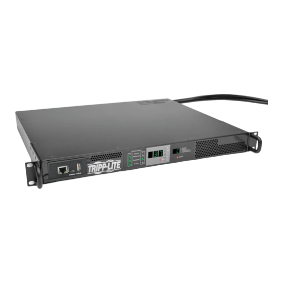
PDUMNH16HVAT
(Series Number: AG-0135)
PDUMNH30HVAT
(Series Number: AG-012F)
PROTECT YOUR INVESTMENT!
Register your product for quicker service
and ultimate peace of mind.
You could also win an
ISOBAR6ULTRA surge protector-
a $100 value!
www.tripplite.com/warranty
1111 W. 35th Street, Chicago, IL 60609 USA • www.tripplite.com/support
15-09-215-93338F.indb 1
Owner's Manual
2
3
3
5
6
6
8
10
10
13
Copyright © 2015 Tripp Lite. All rights reserved.
PDUMNH20HVAT
(Series Number: AG-0134)
PDUMNH32HVAT
(Series Number: AG-012F)
Registration
Español
1
15
17
18
19
37
55
9/30/2015 4:56:23 PM
Publicidad
Capítulos
Tabla de contenido

Manuales relacionados para Tripp-Lite PDUMNH16HVAT


Resumen de contenidos para Tripp-Lite PDUMNH16HVAT
-
Página 1: Tabla De Contenido
Owner’s Manual PDUMNH16HVAT PDUMNH20HVAT (Series Number: AG-0135) (Series Number: AG-0134) PDUMNH30HVAT PDUMNH32HVAT (Series Number: AG-012F) (Series Number: AG-012F) 1. Important Safety 6. Configuration and Operation 15 Instructions 6.1 Automatic Transfer Switch 2. Installation 7. Service 2.1 Mounting the ATS 8. Warranty and Product 2.2 Connecting the ATS... -
Página 2: Important Safety Instructions
1. Important Safety Instructions SAVE THESE INSTRUCTIONS This manual contains instructions and warnings that should be followed during the installation, operation, and storage of this product. Failure to heed these instructions and warnings may affect the product warranty. • The ATS provides a convenient dongle outlet, but it DOES NOT provide surge or line noise protection for connected equipment. -
Página 3: Installation
2. Installation 2.1 Mounting the ATS The ATS supports 1U rack configurations. Notes: • The instructions described in this guide are for common rack and rack enclosure types and may not be appropriate for all applications. The user must determine the fitness of hardware and procedures before mounting. - Página 4 2. Installation Align the rear segments of the bracket set with the cage nuts. Insert and tighten four Phillips pan-head screws (provided with your rack enclosure). Attach Front Rail Segments to the Automatic Transfer Switch Align the front rail segments of the bracket set with the corresponding holes located on the sides of the Automatic Transfer Switch (ATS).
-
Página 5: Connecting The Ats
2. Installation Align the front and rear bracket segments and slide the front rail segments onto the rear rail segments. Align the mounting ears on the ATS with the front vertical mounting rails of the enclosure. Then insert and tighten four Phillips flat-head mounting screws with cup washers (provided with your rack enclosure). -
Página 6: Networking The Ats
NEMA L6-20P NEMA L6-30P IEC 309 32A BLUE (2P + E)* BLUE (2P + E) Model Input Plug Type Output Receptacle Type PDUMNH16HVAT IEC 309 16/20A BLUE (2P + E)* IEC 309 16/20A PDUMNH20HVAT NEMA L6-20P NEMA L6-20R PDUMNH30HVAT NEMA L6-30P... - Página 7 3. Features Digital Display: Shows source status, measured values, display modes and other information. See the Digital Display section for detailed explanations of the indicators and displays. Network Interface: Use the RJ-45 jack to connect the ATS to the network with a shielded Ethernet patch cable.
-
Página 8: Digital Display
4. Digital Display Source Status LEDs: Lit LED patterns indicate which source is preferred, which are available for use, and which is currently being used. See Source Status LED Indicators section for an explanation of the LED patterns. 3-Digit Display: Shows measured or calculated values such as Amperage, Kilowatts, Voltage, Frequency, Power Factor and Temperature. - Página 9 4. Digital Display Source Status LED Indicators LED pattern Description Lit LED Unlit LED • Source A preferred • Both sources of good quality and available • Output is connected to Source A • Source B preferred • Both sources of good quality and available •...
-
Página 10: Using The Digital Display
5. Using the Digital Display 5.1 Navigating Display Menus and Submenus (Measurement) Press the MODE button to go to the next Display menu. Press the Enter button to go to the next submenu (Amps, kW, Volts, Hz, PF). Press and hold MODE button for 2 seconds to switch to the first Config menu (Refer to Navigating Config Menus and Submenus section). - Página 11 5. Using the Digital Display Source B Current i.3.2 Volts 2.0.8 Output Load Circuit Circuit Current i 3.2 Kilowatts 4.8 5 15-09-215-93338F.indb 11 9/30/2015 4:56:30 PM...
- Página 12 5. Using the Digital Display Voltage Circuit Current (Page 9) 2 0 8 Power Factor i.0 0 Temperature tC = Celsius; tF = Fahrenheit Source A Current (Page 8) IP Address Display At any time you can press and hold both Mode and Enter buttons for 2 seconds to show the IP address of the connected SNMP card.
-
Página 13: Navigating Config Menus And Submenus
5. Using the Digital Display 5.2 Navigating Config Menus and Submenus (Configuration) While in any Display Menu, press and hold Mode button for 2 seconds to enter the first Config menu. Press Mode button to cycle to the next Config menu. Press and hold Mode button for 2 seconds to switch to Display menus. -
Página 14: Led Brightness
5. Using the Digital Display LED Brightness Hold the Enter button for 2 seconds to scroll through each brightness option. The number in the 2-digit display is defined as: 1=25%; 2=50%; 3=75%; 4=100%. Note: The default brightness option is 4 (100%). 2 Seconds 2 Seconds 2 Seconds... -
Página 15: Configuration And Operation
6. Configuration and Operation 6.1 Automatic Transfer Switch When the Source A and Source B inputs are both connected to power sources, the ATS operates as an Automatic Transfer Switch, providing redundant input power for high availability applications. The ATS will distribute power from the preferred input source under normal operating conditions and switch to the other input source under abnormal conditions. -
Página 16: Quick Test
6. Configuration and Operation 6.1.2 Automatic Transfer Switch Source Selection The ATS will power up and supply output if at least one of the inputs is greater than the minimum startup voltage. In normal operation, when both sources are of equal quality (“fair” or “good”), the unit will select the preferred source according to the preferred source selection setting (Refer to the Navigating Config Menus and Submenus section). -
Página 17: Service
7. Service Your Tripp Lite product is covered by the warranty described in this manual. A variety of Extended Warranty and On-Site Service Programs are also available from Tripp Lite. For more information on service, visit www.tripplite.com/support. Before returning your product for service, follow these steps: 1. -
Página 18: Warranty And Product
8. Warranty and Product Registration LIMITED WARRANTY Seller warrants this product, if used in accordance with all applicable instructions, to be free from original defects in material and workmanship for a period of 3 years from the date of initial purchase. If the product should prove defective in material or workmanship within that period, Seller will repair or replace the product, in its sole discretion. -
Página 19: Español
Manual del Propietario PDUMNH16HVAT PDUMNH20HVAT (Número de Serie: AG-0135) (Número de Serie: AG-0134) PDUMNH30HVAT PDUMNH32HVAT (Número de Serie: AG-012F) (Número de Serie: AG-012F) 1. Instrucciones de 6. Configuración y Operación Seguridad Importantes 6.1 Switch de Transferencia Automática 2. Instalación 7. Servicio 2.1 Instalación del ATS... -
Página 20: Instrucciones De Seguridad Importantes
1. Instrucciones de Seguridad Importantes CONSERVE ESTAS INSTRUCCIONES Este manual contiene instrucciones y advertencias que deben seguirse durante la instalación, operación y almacenamiento de este producto. La omisión en la observancia de estas instrucciones y advertencias puede afectar la garantía del producto. •... -
Página 21: Instalación
2. Instalación 2.1 Instalación del ATS El ATS es compatible con configuraciones de 1U de rack. Notas: • Las instrucciones descritas en esta guía son para tipos comunes de racks y gabinetes y pueden no ser apropiados para todas las aplicaciones. Antes de la instalación, el usuario debe determinar la adecuación de los accesorios y procedimientos. - Página 22 2. Instalación Alinee los segmentos posteriores del juego de soporte con las tuercas de fijación. Inserte y apriete cuatro tornillos Phillips de cabeza plana (suministrados con su gabinete). Coloque los Segmentos de Riel Frontal al Switch de Transferencia Automática Alinee los segmentos del riel frontal del juego de soportes con los orificios correspondientes localizados en los costados del Switch de Transferencia...
-
Página 23: Conexión Del Ats
2. Instalación Alinee los segmentos de soportes anteriores y posteriores y deslice los segmentos delanteros de riel en los segmentos posteriores de riel. Alinee las orejas de instalación en el ATS con los rieles verticales frontales de instalación del gabinete. Entonces inserte y apriete cuatro tornillos de instalación Phillips de cabeza plana con arandelas de copa (suministrados con su gabinete). -
Página 24: Conexión Del Ats A La Red
NEMA L6-20P NEMA L6-30P IEC 309 32A AZUL (2P + T)* AZUL (2P + T) Modelo Clavija de Entrada Tomacorriente PDUMNH16HVAT IEC 309 16/20A AZUL (2P + T)* IEC 309 16/20A PDUMNH20HVAT NEMA L6-20P NEMA L6-20R PDUMNH30HVAT NEMA L6-30P NEMA L6-30R... - Página 25 3. Características Pantalla Digital: Muestra el estado de la fuente, valores medidos, modos de pantalla y otra información. Consulte la sección de Pantalla Digital para una explicación detallada de los indicadores y pantallas. Interfaz de Red: Use el conector RJ45 para conectar el ATS a la red con el cable patch Ethernet blindado.
-
Página 26: Pantalla Digital
4. Pantalla Digital LEDs de Estado de la Fuente: Los patrones de LED encendido indican qué fuente es preferida, cuál está disponible para uso y cuál se está usando actualmente. Consulte la sección de Indicadores de LED del Estado de la Fuente para una explicación de los patrones de LED. Pantalla de 3 Dígitos: Muestra los valores medidos o calculados Amperaje, Kilowatts, Voltaje, Frecuencia, Factor de Potencia y Temperatura. -
Página 27: Indicadores Led Del Estado De Fuente
4. Pantalla Digital Indicadores LED del Estado de Fuente Patrón de LED Descripción LED Encendido LED Apagado • Fuente A preferida • Ambas fuentes de buena calidad y disponibles. • La salida está conectada a la Fuente A • Fuente B preferida •... -
Página 28: Uso De La Pantalla Digital
5. Uso de la Pantalla Digital 5.1 Menúes de Pantalla de Navegación y Sub Menúes (Medición) Oprima el botón MODE para ir al siguiente menú de pantalla. Oprima el botón Enter para ir al siguiente menú secundario (Amperes, kW, Volts, Hz, PF). Oprima y sostenga por 2 segundos el botón MODE para cambiar al primer menú... -
Página 29: Circuito De Carga De Salida
5. Uso de la Pantalla Digital Fuente B Corriente i.3.2 Volts 2.0.8 Circuito de Carga de Salida Corriente del Circuito i 3.2 Kilowatts 4.8 5 15-09-215-93338F.indb 29 9/30/2015 4:56:38 PM... -
Página 30: Información De La Dirección Ip
5. Uso de la Pantalla Digital Voltaje Corriente del Circuito (Pág. 25) 2 0 8 Factor de Potencia i.0 0 Temperatura tC = Celsius; tF = Fahrenheit Corriente de la Fuente A (Pág. 24) Información de la Dirección IP En cualquier momento puede oprimir y sostener los botones de Mode y Enter durante 2 segundos para mostrar la dirección IP de la tarjeta SNMP conectada. -
Página 31: Menúes De Configuración De Navegación Y Sub Menúes (Configuración)
5. Uso de la Pantalla Digital 5.2 Menúes de Configuración de Navegación y Sub Menúes (Configuración) Estando en cualquier menú de pantalla, oprima y sostenga el botón de Modo por 2 segundos para ingresar el primer menú de configuración. Para cambiar al siguiente menú de configuración, oprima el botón de Modo. -
Página 32: Brillo Del Led
5. Uso de la Pantalla Digital Brillo del LED Sostenga por 2 segundos el botón Enter para desplazarse a través de cada opción de brillo. El número en la pantalla de 2 dígitos se define como: 1=25%; 2=50%; 3=75%; 4=100%. Nota: La opción de brillo predeterminado es 4 (100%). -
Página 33: Configuración Y Operación
6. Configuración y Operación 6.1 Switch de Transferencia Automática Cuando las entradas de la Fuente A y de la Fuente B están conectadas a las fuentes de energía, el ATS opera como un Switch de Transferencia Automática, proporcionando energía redundante de entrada para aplicaciones de alta disponibilidad. -
Página 34: Selección De La Fuente Del Switch De Transferencia Automática
6. Configuración y Operación 6.1.2 Selección de la fuente del Switch de Transferencia Automática El ATS se encenderá y proporcionará salida si al menos una de las entradas es mayor que el voltaje mínimo de arranque. En operación normal, cuando ambas fuentes sean de calidad igual (“aceptable”... -
Página 35: Servicio
7. Servicio Su producto Tripp Lite está cubierto por la garantía descrita en este manual. Está disponible una variedad de Programas de Garantía Extendida y Servicio En el Sitio por parte de Tripp Lite. Para información adicional acerca del servicio, visite www.tripplite.com/support. Antes de regresar su producto para servicio, siga estos pasos: 1. -
Página 36: Garantía
8. Garantía GARANTÍA LIMITADA El vendedor garantiza este producto, si se usa de acuerdo con todas las instrucciones aplicables, de que está libre de defectos en material y mano de obra por un período de 3 años a partir de la fecha de compra inicial. Si el producto resulta defectuoso en material o mano de obra dentro de ese período, el vendedor reparará... -
Página 37: Français
Manuel de l'utilisateur PDUMNH16HVAT PDUMNH20HVAT (Numéro de série : AG-0135) (Numéro de série : AG-0134) PDUMNH30HVAT PDUMNH32HVAT (Numéro de série : AG-012F) (Numéro de série : AG-012F) 1. Consignes de sécurité 6. Configuration et importantes fonctionnement 6.1 Commutateur de transfert 2. -
Página 38: Consignes De Sécurité Importantes
1. Consignes de sécurité importantes CONSERVEZ CES INSTRUCTIONS Ce manuel contient des instructions et des avertissements qui devraient être respectés pendant l'installation, l'utilisation et l'entreposage de ce produit. Le non-respect de ces instructions et de ces avertissements pourrait avoir une incidence sur la garantie du produit. •... -
Página 39: Installation
2. Installation 2.1 Montage du commutateur de transfert automatique Le commutateur de transfert automatique peut accueillir les configurations en bâti 1U. Remarques : • Les instructions décrites dans ce guide s’appliquent aux types de bâtis et d’enceintes ordinaires et peuvent ne pas être appropriées à... - Página 40 2. Installation Aligner les segments arrière de l’ensemble du support avec les écrous à cage. Insérer et serrer quatre vis à tête fraisée Phillips (fournies avec l’enceinte pour bâti). Fixer les segments de rail avant au commutateur de transfert automatique Aligner les segments de rail avant de l’ensemble de rails avec les trous correspondants situés sur les côtés du...
-
Página 41: Raccordement Du
2. Installation Aligner les segments de support avant et arrière et glisser les segments de rail avant dans les segments de rail arrière. Aligner les oreilles de montage sur le commutateur de transfert automatique avec les rails de montage vertical de l’enceinte. -
Página 42: Caractéristiques
2. Installation 2.3 Fonctionnement en réseau du commutateur de transfert automatique Le commutateur de transfert automatique peut se voir assigner des adresses IP via le serveur DHCP (dynamique) ou par des méthodes d'adressage statique (manuelles). En cas de doute sur la méthode à... - Página 43 NEMA L6-30P IEC 309 DE 32 A BLEU (2P + T)* BLEU (2P + T) Modèle Fiche d’entrée Sortie PDUMNH16HVAT IEC 309 DE 6/20 A BLEU (2P + T)* IEC 309 DE 6/20 A PDUMNH20HVAT NEMA L6-20P NEMA L6-20R PDUMNH30HVAT...
-
Página 44: Affichage Numérique
4. Affichage numérique Voyants à DEL Status (état) de la source : Le type d'illumination des voyants à DEL indique quelle source est la source principale, quelle source est prête à l'utilisation et quelle source est actuellement utilisée. Consulter la section Voyants à DEL Status (état) de la source pour une explication sur la signification de l'allumage des voyants à... -
Página 45: Voyants À Del Status (État) De La Source
4. Affichage numérique Voyants à DEL Status (état) de la source Voyant à DEL Illumination des allumé voyants à DEL Description Voyant à DEL éteint • Source A principale • Les deux sources sont de bonne qualité et disponibles. • La sortie est raccordée à la source A. •... -
Página 46: Utilisation De L'affichage
5. Utilisation de l'affichage numérique 5.1 Navigation des menus et des sous-menus d'affichage (mesure) Appuyer sur le bouton MODE pour passer au menu d'affichage suivant. Appuyer sur le bouton Enter (saisir) pour passer au sous-menu suivant (ampères, kW, volts, Hz, PF). Appuyer et maintenir le bouton MODE pendant 2 secondes pour passer au premier menu de configuration (Se reporter à... -
Página 47: Circuit De Charge De Sortie
5. Utilisation de l'affichage numérique Source B Courant i.3.2 volts 2.0.8 Circuit de charge de sortie Courant du circuit i 3.2 Kilowatts 4.8 5 15-09-215-93338F.indb 47 9/30/2015 4:56:45 PM... - Página 48 5. Utilisation de l'affichage numérique Tension Courant du circuit (Page 41) 2 0 8 Facteur de puissance i.0 0 Température tC = Celsius; tF = Fahrenheit Courant de la source A (Page 40) Affichage de l'adresse IP Il est possible d'appuyer et de maintenir à tout moment les boutons Mode et Enter (saisir) pendant 2 secondes pour afficher l'adresse IP de la carte SNMP connectée.
-
Página 49: Navigation Des Menus Et Des
5. Utilisation de l'affichage numérique 5.2 Navigation des menus et des sous-menus de configuration Depuis n'importe quel menu d'affichage, appuyer et maintenir le bouton Mode pendant 2 secondes pour accéder au premier menu de configuration. Appuyer sur le bouton Mode pour passer au menu de configuration suivant. - Página 50 5. Utilisation de l'affichage numérique Luminosité des voyants à DEL Maintenir le bouton Enter (saisir) enfoncé pendant 2 secondes pour parcourir chaque option de luminosité. Le chiffre sur l'afficheur à 2 chiffres est défini de la façon suivante : 1=25 %; 2=50 %; 3=75 %;...
-
Página 51: Configuration Et Fonctionnement
6. Configuration et fonctionnement 6.1 Commutateur de transfert automatique Lorsque les entrées de la source A et de la source B sont toutes les deux raccordées aux sources d'alimentation, le commutateur de transfert automatique fonctionne comme un commutateur de transfert automatique, fournissant de l'alimentation d'entrée redondante pour les applications à disponibilité... - Página 52 6. Configuration et fonctionnement 6.1.2 Sélection de la source pour le commutateur de transfert automatique Le commutateur de transfert automatique va démarrer et fournir une sortie si la tension de l'une des sources d'entrée est supérieure à la tension minimum de démarrage. Lors du fonctionnement normal, lorsque les deux sources sont de même qualité...
-
Página 53: Entretien
7. Entretien Votre produit Tripp Lite est couvert par la garantie décrite dans le présent manuel. Une variété de programmes de garantie prolongée et de service d'entretien sont également disponibles par Tripp Lite. Pour plus d'informations sur le service, visitez www.tripplite.com/support. Avant de retourner votre produit pour le service, procédez comme suit : 1. -
Página 54: Garantie
8. Garantie GARANTIE LIMITÉE Le vendeur garantit que ce produit, s'il est utilisé conformément à toutes les instructions applicables, est exempt de tous défauts de matériaux et de fabrication pour une période de 3 ans à partir de la date d'achat initiale. Si le produit s'avère défectueux en raison d'un vice de matière ou de fabrication au cours de cette période, le vendeur s'engage à... -
Página 55: Руководство Пользователя
Руководство пользователя PDUMNH16HVAT PDUMNH20HVAT (серийный номер: AG-0135) (серийный номер: AG-0134) PDUMNH30HVAT PDUMNH32HVAT (серийный номер: AG-012F) (серийный номер: AG-012F) 1. Важные указания по 6. Порядок настройки и технике безопасности эксплуатации 2. Установка 6.1 Автоматический ввод резерва 69 7. Обслуживание 2.1 Монтаж модуля ATS 8. -
Página 56: Важные Указания По Технике Безопасности
1. Важные указания по технике безопасности СОХРАНИТЕ НАСТОЯЩИЕ УКАЗАНИЯ В настоящем руководстве содержатся указания и предупреждения, которые необходимо соблюдать в процессе установки, эксплуатации и хранения данного изделия. Игнорирование этих указаний и предупреждений может привести к потере гарантии на изделие. • Модуль ATS оснащен удобным выходным разъемом с аппаратным ключом, но НЕ обеспечивает защиту подключенного оборудования... -
Página 57: Установка
2. Установка 2.1 Монтаж модуля ATS Модуль ATS поддерживает конфигурации с использованием стоек размером 1U. Примечания: • Указания, изложенные в настоящем руководстве, предназначены для обычных типов шкафов и могут не подходить для всех целей применения. Пользователь должен установить пригодность оснастки и предполагаемых... - Página 58 2. Установка Совместите задние сегменты комплекта кронштейнов с закладными гайками. Вставьте и затяните четыре винта с плоско-конической головкой и крестообразным шлицем (поставляемые в комплекте с вашим шкафом). Крепление передних сегментов направляющих к блоку автоматического переключения нагрузки Совместите передние сегменты направляющих комплекта...
-
Página 59: Подключение Модуля Ats
2. Установка Совместите передние и задние сегменты кронштейнов и надвиньте передние сегменты направляющих на задние сегменты. Совместите монтажные уши блока ATS с передними вертикальными монтажными направляющими шкафа. Затем вставьте и затяните четыре монтажных винта с плоской потайной головкой и крестообразным шлицем с чашеобразными... -
Página 60: Включение Модуля Ats В Сеть
NEMA L6-20P NEMA L6-30P IEC 309 32A СИНЕГО ЦВЕТА (2P + E)* СИНЕГО ЦВЕТА (2P + E) Модель Входной разъем Розетки PDUMNH16HVAT IEC 309 16/20A СИНЕГО ЦВЕТА (2P + E)* IEC 309 16/20A PDUMNH20HVAT NEMA L6-20P NEMA L6-20R PDUMNH30HVAT NEMA L6-30P... - Página 61 3. Возможности Цифровой дисплей: отображает статус источника, результаты измерений, режимы отображения и прочую информацию. Подробные разъяснения показаний индикаторов и отображаемой информации см. в разделе "Цифровой дисплей". Сетевой интерфейс: используйте разъем типа RJ-45 для подключения модуля ATS к сети с помощью экранированного соединительного кабеля типа Ethernet. СИД Link (Связь) и...
-
Página 62: Цифровой Дисплей
4. Цифровой дисплей Светодиодные индикаторы статуса источника: сочетания горящих светодиодных индикаторов указывают на то, какой источник является предпочтительным, какие из них готовы к использованию и какие используются в настоящее время. Разъяснение значений различных сочетаний светодиодных индикаторов см. в разделе "Светодиодные индикаторы... - Página 63 4. Цифровой дисплей Светодиодные индикаторы статуса источника Описание сочетаний светодиодных индикаторов Горящий СИД Негорящий СИД • Предпочтительный источник: A • Оба источника качественны и доступны • Выходная нагрузка подключена к источнику A • Предпочтительный источник: В • Оба источника качественны и доступны •...
-
Página 64: Использование Цифрового
5. Использование цифрового дисплея 5.1 Перемещение по экранным меню и подменю (измерение) Для перехода к следующему меню отображения нажмите на кнопку переключения режимов (MODE). Для перехода к следующему подменю (Амперы, кВт, Вольты, Гц, КМ) нажмите на кнопку ввода (Enter). Для перехода в первое меню настройки нажмите кнопку переключения... - Página 65 5. Использование цифрового дисплея Источник B Ток i.3.2 Вольт 2.0.8 Гц Цепь выходной нагрузки Ток цепи i 3.2 киловатт 4.8 5 15-09-215-93338F.indb 65 9/30/2015 4:56:51 PM...
- Página 66 5. Использование цифрового дисплея Напряжение Ток цепи (стр. 57) 2 0 8 Коэффициент электрической мощности i.0 0 Температура Источник A Ток (стр. 56) tC = по Цельсию; tF = по Фаренгейту Отображение IP-адреса Для отображения IP-адреса подключенной SNMP-карты вы можете одновременно нажать кнопки MODE и Enter и удерживать их в течение...
-
Página 67: Перемещение По Настроечным Меню И Подменю
5. Использование цифрового дисплея 5.2 Перемещение по настроечным меню и подменю (настройка) Находясь в любом из меню отображения (Display), нажмите кнопку переключения режимов (Mode) и удерживайте ее в течение 2 секунд для входа в первое меню настройки (Config). Для перехода к следующему меню настройки (Config) нажмите кнопку переключения... - Página 68 5. Использование цифрового дисплея Яркость СИД Для прокрутки опций яркости удерживайте кнопку ввода (Enter) в течение 2 секунд. Цифры, отображаемые на 2-разрядном дисплее, расшифровываются следующим образом: 1=25%; 2=50%; 3=75%; 4=100%. Примечание. Уровень яркости по умолчанию: 4 (100%). 2 секунды 2 секунды 2 секунды...
-
Página 69: Порядок Настройки И
6. Порядок настройки и эксплуатации 6.1 Автоматический ввод резерва В тех случаях, когда подключены оба источника А и В, модуль ATS работает в качестве средства автоматического ввода резерва, обеспечивая резервное входное электропитание для систем высокой доступности. При нормальных условиях эксплуатации модуль... - Página 70 6. Порядок настройки и эксплуатации 6.1.2 Выбор источника для автоматического ввода резерва Модуль ATS обеспечивает включение и подачу электропитания на выходную нагрузку в том случае, если напряжение, обеспечиваемое хотя бы одним из входных источников, превышает минимальное пусковое напряжение. При нормальных условиях...
-
Página 71: Обслуживание
7. Обслуживание На приобретенное вами изделие марки Tripp Lite распространяется действие гарантии, условия которой изложены в настоящем руководстве. Кроме того, компания Tripp Lite предлагает ряд Программ расширенной гарантии и обслуживания на объекте. Более подробная информация о техническом обслуживании изложена на странице www.tripplite.com/support. Перед возвратом своего изделия... -
Página 72: Гарантийные Обязательства
8. Гарантийные обязательства ОГРАНИЧЕННАЯ ГАРАНТИЯ Продавец гарантирует отсутствие изначальных дефектов материала или изготовления в течение 3 лет с момента первой покупки данного изделия при условии его использования в соответствии со всеми применимыми к нему указаниями. В случае проявления каких-либо дефектов материала или...