Genius BRAIN 03 Instrucciones Para El Uso
Ocultar thumbs
Ver también para BRAIN 03:
- Manual de instrucciones para el uso y el mantenimiento (61 páginas) ,
- Instrucciones para el uso (68 páginas)
Tabla de contenido
Publicidad
Idiomas disponibles
Idiomas disponibles
Enlaces rápidos
BRAIN 03
BRAIN 04
ISTRUZIONI PER L'USO - NORME DI INSTALLAZIONE
INSTRUCTIONS FOR USE - DIRECTIONS FOR INSTALLATION
INSTRUCTIONS - REGLES D'INSTALLATION
INSTRUCCIONES PARA EL USO - NORMAS PARA LA INSTALACION
GEBRAUCHSANLEITUNG - ANWEISUNGEN ZUR INSTALLATION
GEBRUIKSAANWIJZINGEN – INSTALLATIEVOORSCHRIFTEN
24V / 230V
24V / 115V
Publicidad
Capítulos
Tabla de contenido

Manuales relacionados para Genius BRAIN 03


Resumen de contenidos para Genius BRAIN 03
- Página 1 BRAIN 03 24V / 230V BRAIN 04 24V / 115V ISTRUZIONI PER L’USO - NORME DI INSTALLAZIONE INSTRUCTIONS FOR USE - DIRECTIONS FOR INSTALLATION INSTRUCTIONS - REGLES D’INSTALLATION INSTRUCCIONES PARA EL USO - NORMAS PARA LA INSTALACION GEBRAUCHSANLEITUNG - ANWEISUNGEN ZUR INSTALLATION...
- Página 2 22) Interdire aux enfants ou aux tiers de stationner près du produit durant le 6) GENIUS declines all liability caused by improper use or use other than that for fonctionnement.
-
Página 3: Tabla De Contenido
89/336/CEE e successiva modifica 92/31/CEE e 93/68/CEE Nota aggiuntiva: Nota aggiuntiva: Questo prodotto è stato sottoposto a test in una configurazione tipica omogenea (tutti prodotti di costruzione GENIUS Questo prodotto è stato sottoposto a test in una configurazione tipica omogenea (tutti prodotti di costruzione GENIUS S.p.A.) Grassobbio, 10-01-2007 L’Amministratore Delegato... -
Página 4: Caratteristiche Generali
APPARECCHIATURA ELETTRONICA 24Vdc PER CANCELLI AD ANTE BATTENTI ISTRUZIONI PER L’USO - NORME D’INSTALLAZIONE 1. CARATTERISTICHE GENERALI Questa centrale di comando a 24Vdc per cancelli ad ante battenti offre elevate prestazioni ed un ampio numero di regolazioni, con rallentamenti in apertura e chiusura, possibilità di gestire uno o due motori, gestione dei finecorsa in apertura e chiusura e possibilità... -
Página 5: Collegamenti E Funzionamento
4. COLLEGAMENTI E FUNZIONAMENTO 4.1. MORSETTIERA CN1 4.1.1. A LIMENTAZIONE Morsetti “VAC-VAC”. Ingresso al quale va collegato il circuito secondario del trasformatore 24V~ 50/60 Hz. La pre- senza d’alimentazione per mezzo del trasformatore è segnalata dall’accensione del led “ALIM” posizionato sotto la morsettiera. -
Página 6: Morsettiera Cn3
4.3. MORSETTIERA CN3 4.3.1. F INECORSA IN CHIUSURA MOTORE Morsetti “COMF - FCC1”. Contatto normalmente chiuso. Questo interviene bloccando il moto di chiusura del motore 1. Lo stato di questo ingresso è segnalato dal led FCC1. 4.3.2. F INECORSA IN APERTURA MOTORE Morsetti “COMF - FCA1”. -
Página 7: Inserimento Scheda Ricevitore Per Radiocomando
4.4.5. S ICUREZZE IN APERTURA Morsetti “COM - FSW OP”. Contatto normalmente chiuso. Collegare a questi morsetti un qualsiasi dispositivo di sicu- rezza (es. fotocellula, costa, pressostato, etc..) che, aprendo un contatto, agisce sul moto d’apertura del cancello provocandone l’arresto immediato, una volta ripristinata la sicurezza il cancello riprende con il ciclo memorizzato. Lo stato di questo ingresso è... -
Página 8: Regolazione Dei Parametri Di Funzionamento
Durante il funzionamento normale il display visualizza lo stato del cancello. I valori visualizzati sono riportati nella tabella seguente: VALORE STATO CANCELLO VISUALIZZATO Cancello a riposo Cancello in apertura Cancello aperto in pausa (Solo con richiusura automatica abilitata, vedi paragrafo successivo) Cancello in chiusura 9. -
Página 9: Programmazione
DISPLAY DESCRIZIONE Percentuale punto di rallentamento: con questo parametro si imposta la lunghezza del tratto rallentato, scegliendo tra i due valori prefissati 40% della massima apertura memorizzata 20% della massima apertura memorizzata Velocità durante la fase rallentata: con questo parametro è possibile impostare la velocità del motore durante la fase rallentata, scegliendo tra i due valori rallentata, scegliendo tra i due valori rallentata, scegliendo tra i due valori... -
Página 10: Fusibili Di Protezione
12. FUSIBILI DI PROTEZIONE FUSIBILE PROTEZIONE FUSIBILE PROTEZIONE FUSIBILE PROTEZIONE FUSIBILE PROTEZIONE Alimentazio- F1=T10A Alimentazio- F2=T0.63A ne accessori F3=R0.63A Uscita lam- F4=R3.15A Uscita elettro- 250V - 5x20 ne 24V~ 250V - 5x20 e caricabat- 250V - 5x20 peggiante 250V - 5x20 serratura terie 13. -
Página 13: Fissaggio Scheda
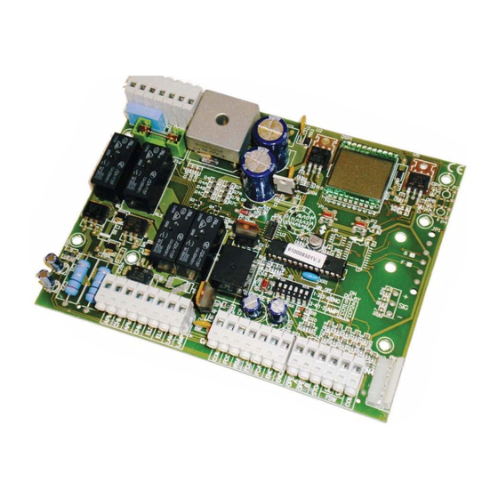
15. FISSAGGIO SCHEDA Il contenitore da esterno è predisposto per l’alloggiamento della centrale, del trasformatore toroidale e delle eventuali batterie tampone (Optional). Per il fissaggio del trasformatore toroidale e del supporto scheda fare riferimento alle specifiche istruzioni. Per il fissaggio della scheda elettronica seguire le seguenti istruzioni: 1. -
Página 14: Gianantoni
• conforms to the essential safety requirements of the following EEC directives: 73/23/EEC and subsequent amendment 93/68/EEC. 89/336/EEC and subsequent amendment 92/31/EEC and 93/68/EEC Additional information: This product underwent a test in a typical uniform configuration (all products manufactured by GENIUS S.p.A.). Grassobbio, 10-01-2007 Managing Director D. Gianantoni Notes on reading the instruction Read this installation manual to the full before you begin installing the product. -
Página 15: General Characteristics
24 Vdc ELECTRONIC CONTROL UNIT FOR SWING GATES USE INSTRUCTIONS - INSTALLATION INSTRUCTIONS 1. GENERAL CHARACTERISTICS This 24 Vdc control unit for swing gates offers high performance and a wide range of adjustments: opening and closing decelerations, possibility of managing one or two motors, management of opening and closing limit-switches, and the possibility of managing two TIMECODERS. -
Página 16: Connections And Operation
4. CONNECTIONS AND OPERATION 4.1. TERMINAL BOARD CN1 4.1.1. P OWER SUPPLY “VAC-VAC” terminals. The secondary circuit of the 24V~ 50/60 Hz transformer should be connected to this input. Power supplied by the transformer is signalled by the lighting of the “ALIM” LED located under the terminal board. 4.1.2. -
Página 17: Terminal Board Cn3
4.3. TERMINAL BOARD CN3 4.3.1. M OTOR CLOSING LIMIT SWITCH “COMF - FCC1” terminals. Normally closed contact. This is tripped and stops the closing motion of motor 1. The status of this input is signalled by LED FCC1. 4.3.2. M OTOR OPENING LIMIT SWITCH... -
Página 18: Installing The Radio Control Receiver Board
4.4.5. O PENING SAFETY DEVICES “COM - FSW OP”terminals. Normally closed contact. Connect, to these terminals, any safety device (e.g. photocell, safety edge, pressure switch etc..) which, by opening a contact, affects the gate’s opening motion, causing it to stop immediately. -
Página 19: Adjusting The Operating Parameters
During normal operation, the display shows gate status. The displayed values are indicated on the following table: DISPLAY VALUE GATE STATUS Gate at rest Gate opening Gate open in pause status (Only with automatic re-closure enabled - see next paragraph) Gate closing 9. -
Página 20: Programming
DISPLAY DESCRIPTION Deceleration point percentage: this parameter is used to set the length of the decelerated section, selecting from the two set values. 40% of maximum memory-stored opening 20% of maximum memory-stored opening Speed during deceleration phase: this parameter is used to set motor speed during the deceleration phase, selecting it from the two values. -
Página 21: Protection Fuses
12. PROTECTION FUSES FUSE PROTECTION FUSE PROTECTION FUSE PROTECTION FUSE PROTECTION Supply to F1=T10A Power supply F2=T0.63A accessories F3=R0.63A Flashing lamp F4=R3.15A Electric lock 250V - 5x20 24V~ 250V - 5x20 and battery- 250V - 5x20 output 250V - 5x20 output charger 13. -
Página 24: How To Secure The Board
15. HOW TO SECURE THE BOARD The outdoor enclosure is designed to house the control unit, the toroidal transformer and any buffer batteries (Optional). To secure the toroidal transformer and the board support, consult the specific instruc- tions. To secure the control board, follow the instructions below: 1. -
Página 25: Gianantoni
• est conforme aux exigences essentielles de sécurité des directives CEE suivantes: 73/23/CEE et modification 93/68/CEE successive. 89/336/CEE et modifications 92/31/CEE et 93/68/CEE successives. Note supplémentaire: Ce produit a été testé dans une configuration typique homogène (tous les produits sont fabriqués par GENIUS S.p.A.) Grassobbio, le 10-10-2007 L’Administrateur Délégué D. Gianantoni Remarques pour la lecture de l’instruction... -
Página 26: Caractéristiques Générales
ARMOIRE ÉLECTRONIQUE 24Vcc POUR PORTAILS BATTANTS INSTRUCTIONS POUR L’EMPLOI - NORMES D’INSTALLATION 1. CARACTÉRISTIQUES GÉNÉRALES Cette centrale de commande à 24Vcc pour portails battants offre de hautes performances et un grand nombre de réglages, avec des ralentissements en ouverture et fermeture, la possibilité de gérer un ou deux moteurs, la gestion des fins de course en ouverture et fermeture et la possibilité... -
Página 27: Connexions Et Fonctionnement
4. CONNEXIONS ET FONCTIONNEMENT 4.1. BORNIER CN1 4.1.1. A LIMENTATION Bornes “VAC-VAC”. Entrée à laquelle doit être relié le circuit secondaire du transformateur 24V~ 50/60 Hz. La présence de l’alimentation par l’intermédiaire du transformateur est signalée par l’éclairage de la LED “ALIM” positionnée sous le bornier. -
Página 28: Bornier Cn3
4.3. BORNIER CN3 4.3.1. F INS DE COURSE EN FERMETURE MOTEUR Bornes “COMF - FCC1”. Contact normalement fermé. Il intervient en bloquant le mouvement de fermeture du moteur 1. L’état de cette entrée est signalé par la LED FCC1. 4.3.2. F INS DE COURSE EN OUVERTURE MOTEUR Bornes “COMF - FCA1”. -
Página 29: Insertion De La Carte Receptrice Pour Radiocommande
4.4.5. S ÉCURITÉS EN OUVERTURE Bornes “COM - FSW OP”. Contact normalement fermé. Connecter à ces bornes un dispositif de sécurité quelconque (ex. photocellule, bord, pressostat, etc.) qui, en ouvrant un contact, agit sur le mouvement d’ouverture du portail en en provoquant l’arrêt immédiat; une fois la sécurité rétablie, le portail reprend le cycle mémorisé. L’état de cette entrée est signalé... -
Página 30: Réglage Des Paramètres De Fonctionnement
Durant le fonctionnement normal, l’afficheur affiche l’état du portail. Les valeurs affichées figurent dans le tableau suivant: VALEUR AFFICHÉE ÉTAT DU PORTAIL Portail au repos Portail en ouverture Portail ouvert en pause (uniquement avec refermeture automatique validée, voir paragraphe suivant) Portail en fermeture 9. -
Página 31: Programmation
AFFICHEUR DESCRIPTION Pourcentage du point de ralentissement: ce paramètre permet de sélectionner la longueur du parcours ralenti, en choisissant parmi les deux valeurs préfixées. 40% de l’ouverture maximum mémorisée 20% de l’ouverture maximum mémorisée Vitesse durant la phase ralentie: ce paramètre permet de programmer la vitesse du moteur durant la phase ralentie, en choisissant parmi les deux valeurs. -
Página 32: Fusibles De Protection
12. FUSIBLES DE PROTECTION FUSIBLE PROTECTION FUSIBLE PROTECTION FUSIBLE PROTECTION FUSIBLE PROTECTION Alimentation F1=T10A Alimentation F2=T0.63A accessoires F3=R0.63A Sortie F4=R3.15A Sortie électro- 250V - 5x20 24V~ 250V - 5x20 et chargeur 250V - 5x20 clignotant 250V - 5x20 serrure de batteries 13. -
Página 35: Fixation De La Carte
15. FIXATION DE LA CARTE Le boîtier pour l’extérieur est disposé pour le logement de la centrale, du transformateur toroïdal et des batteries tampon éventuelles (En option). Pour la fixation du transformateur toroïdal et du support de la carte, consulter les instructions spécifiques. -
Página 36: Gianantoni
Via Padre Elzi, 32 - 24050 - Grassobbio- Bergamo - ITALIA Dirección: Declara que: El equipo mod. BRAIN 03 - BRAIN 04 • cumple con los requisitos esenciales de seguridad de las siguientes directivas CEE: 73/23/CEE y sucesiva modificación 93/68/CEE. -
Página 37: Características Generales
EQUIPO ELECTRÓNICO 24Vdc PARA CANCELAS DE HOJAS BATIENTES INSTRUCCIONES DE USO - NORMAS DE INSTALACIÓN 1. CARACTERÍSTICAS GENERALES Esta central de mando a 24Vdc para cancelas de hojas batientes ofrece elevadas prestaciones y un amplio número de ajustes, con deceleraciones en apertura y cierre, posibilidad de gestionar uno o dos motores, gestión de los finales de carrera de apertura y cierre y posibilidad de gestionar dos TIMECODER. -
Página 38: Conexiones Y Funcionamiento
4. CONEXIONES Y FUNCIONAMIENTO 4.1. REGLETA DE BORNES CN1 4.1.1. A LIMENTACIÓN Bornes “VAC-VAC”. Entrada a la que debe conectarse el circuito secundario del transformador 24V~ 50/60 Hz. La presencia de alimentación por medio del transformador está indicada por el encendido del diodo “ALIM” situado debajo de la regleta de bornes. -
Página 39: Regleta De Bornes Cn3
4.3. REGLETA DE BORNES CN3 4.3.1. F INAL DE CARRERA EN CIERRE MOTOR Bornes “COMF - FCC1”. Contacto normalmente cerrado. El mismo interviene deteniendo el movimiento de cierre del motor 1. El estado de esta entrada está indicado por el diodo FCC1. 4.3.2. -
Página 40: Introducción De La Tarjeta Receptora Para Telemando
4.4.5. D ISPOSITIVOS DE SEGURIDAD EN APERTURA Bornes “COM - FSW OP”. Contacto normalmente cerrado. Conecte a estos bornes un dispositivo de seguridad cualquiera (p.ej. fotocélula, borde, presostato, etc..) el cual, abriendo un contacto, interviene en el movimiento de apertura de la cancela y lo detiene inmediatamente, una vez restablecido el dispositivo de seguridad, la cancela reanuda el movimiento con el ciclo memorizado. -
Página 41: Regulación De Los Parámetros De Funcionamiento
Durante el funcionamiento normal el display visualiza el estado de la cancela. Los valores visualizados se indican en la siguiente tabla: VALOR VISUALI- ESTADO CANCELA ZADO Cancela en reposo Cancela en apertura Cancela abierta en pausa (Sólo con cierre automático habilitado, véase párrafo siguiente) Cancela en cierre 9. -
Página 42: Programación
DISPLAY DESCRIPCIÓN Porcentaje punto de deceleración: con este parámetro se puede seleccionar la longitud del tramo decelerado, escogiendo entre los dos valores prefijados escogiendo entre los dos valores prefijados escogiendo entre los dos valores prefijados 40% de la máxima apertura memorizada 20% de la máxima apertura memorizada Velocidad durante la fase decelerada: con este parámetro se puede programar la velocidad del motor durante la fase decelerada, escogiendo entre los dos valores... -
Página 43: Fusibles De Protección
12. FUSIBLES DE PROTECCIÓN FUSIBLE PROTECCIÓN FUSIBLE PROTECCIÓN FUSIBLE PROTECCIÓN FUSIBLE PROTECCIÓN Alimentación Salida F1=T10A Alimentación F2=T0.63A accesorios y F3=R0.63A Salida destel- F4=R3.15A electrocerra- 250V - 5x20 24V~ 250V - 5x20 cargador de 250V - 5x20 lador 250V - 5x20 dura baterías 13. -
Página 46: Fijación De La Tarjeta
15. FIJACIÓN DE LA TARJETA El contenedor para exteriores está predispuesto para alojar la central, el transformador toroidal y las eventuales baterías tampón (Opcional). Para la fijación del transformador toroidal y del soporte de la tarjeta consulte las cor- respondientes instrucciones. Para la fijación de la tarjeta electrónica proceda del siguiente modo: 1. -
Página 47: Gianantoni
• den wesentlichen Sicherheitsbestimmungen der folgenden EWG-Richtlinien entspricht: 73/23/EWG und nachträgliche Änderung 93/68/EWG 89/336/EWG und nachträgliche Änderung 92/31/EWG und 93/68/EWG Zusätzliche Anmerkungen: Dieses Produkt wurde in einer typischen, homogenen Konfiguration getestet (alle von GENIUS S.r.l. hergestellten Produkte). Grassobbio, 10-01-2007 Geschäftsführer D. -
Página 48: Allgemeine Daten
ELEKTRONISCHES STEUERGERÄT 24Vdc FÜR FLÜGELTORE BETRIEBSANLEITUNGEN – MONTAGEVORSCHRIFTEN 1. ALLGEMEINE DATEN Diese 24Vdc-Steuereinheit für Flügeltore bietet hohe Leistungen und zahlreiche Einstellungsmöglichkeiten mit Abbrem- sungen beim Öffnen und Schließen, der Möglichkeit zur Steuerung von einem oder zwei Motoren, der Steuerung der Endschalter beim Öffnen und Schließen sowie der Steuerung von zwei TIMECODER. -
Página 49: Anschlüsse Und Betriebsweise
4. ANSCHLÜSSE UND BETRIEBSWEISE 4.1. KLEMMENLEISTE CN1 4.1.1. 22V-V ERSORGUNG Klemmen „VAC-VAC”. Eingang, an den der Nebenstromkreis des Transformators 24V-50/60 Hz anzuschließen ist. Die Versor- gung über den Transformator wird durch das Aufleuchten der LED „ALIM” unterhalb der Klemmenleiste angezeigt. 4.1.2. -
Página 50: Klemmenleiste Cn3
4.3. KLEMMENLEISTE CN3 4.3.1. E NDSCHALTER BEIM CHLIESSEN OTOR Klemmen „COMF - FCC1”. Ruhekontakt. Dieser Kontakt löst mit der Sperre der Schließbewegung des Motors 1 aus. Der Zustand dieses Eingangs wird von der LED FCC1 signalisiert. 4.3.2. E Ö NDSCHALTER BEIM FFNEN OTOR Klemmen „COMF - FCA1”. -
Página 51: Einsetzen Der Empfängerkarte Für Die Funksteuerung
4.4.5. S Ö ICHERHEITSVORRICHTUNGEN BEIM FFNEN Klemmen „COM - FSW OP”. Ruhekontakt. An diese Klemmen eine beliebige Sicherheitsvorrichtung anschließen (z.B. Photozelle, Leiste, Druckwächter usw.), die beim Öffnen eines Kontakts auf die Öffnungsbewegung des Tors wirkt und den unverzüglichen Stopp bewirkt. Nach der Wiederherstellung der Sicherheitsvorrichtung nimmt das Tor den gespei- cherten Zyklus wieder auf. -
Página 52: Einstellung Der Betriebsparameter
Während des Normalbetriebs erscheint der Zustand des Tors auf dem Display. Die angezeigten Werte sind in der na- chfolgenden Tabelle aufgeführt: ANGEZEIGTER WERT ZUSTAND DES TORS Tor in Ruhestellung Tor öffnet sich Tor offen in Pause (nur bei eingeschalteter automatischer erneuter Schließung, siehe nachfolgender Abschnitt) Tor schließt sich 9. -
Página 53: Programmierung
DISPLAY BESCHREIBUNG Anteil Abbremsungsstelle: Mit diesem Parameter wird die Länge des abgebremsten Wegs eingestellt, wobei zwischen zwei festgesetzten Werten ausgewählt werden kann. zwei festgesetzten Werten ausgewählt werden kann. zwei festgesetzten Werten ausgewählt werden kann. 40% der maximalen gespeicherten Öffnung 20% der maximalen gespeicherten Öffnung Geschwindigkeit während der Abbremsung: Mit diesem Parameter kann die Geschwindigkeit des Motors während der Abbremsung eingestellt werden, wobei zwei Werte zur Auswahl stehen. -
Página 54: Schmelzsicherungen
12. SCHMELZSICHERUNGEN SICHERUNG SCHUTZ SICHERUNG SCHUTZ SICHERUNG SCHUTZ SICHERUNG SCHUTZ Versorgung F1=T10A Versorgung F2=T0.63A Zubehör und F3=R0.63A Ausgang F4=R3.15A Ausgang 250V - 5x20 24V~ 250V - 5x20 Batteriela- 250V - 5x20 Blinkleuchte 250V - 5x20 Elektroschloss dung 13. ANSCHLUSSPLAN... -
Página 57: Befestigung Der Karte
15. BEFESTIGUNG DER KARTE Das Gehäuse für die Außenanwendung ist für die Aufnahme der Steuereinheit, des Toroid-Transformators und der eventuellen Pufferbatterien (Extra) ausgelegt. Für die Befestigung des Toroid-Transformators und des Kartenhalters wird auf die spezi- fischen Anweisungen verwiesen. Für die Befestigung der elektronischen Karte sind die nachfolgenden Anweisungen zu befolgen: 1. -
Página 58: Eg-Verklaring Van Overeenstemming
• in overeenstemming is met de fundamentele veiligheidseisen van de volgende EEG-richtlijnen: 73/23/EEG en latere wijziging 93/68/EEG. 89/336/EEG en latere wijzigingen 92/31/EEG en 93/68/EEG Aanvullende opmerking: Dit product is getest in een specifieke homogene configuratie (alle door GENIUS S.p.A. vervaardigde producten). Grassobbio, 10-01-2007 De Algemeen Directeur D. Gianantoni Opmerkingen voor het lezen van de instructies Lees deze installatiehandleiding aandachtig door alvorens te beginnen met de installatie van het product. -
Página 59: Algemene Eigenschappen
ELEKTRONISCHE APPARATUUR 24Vdc VOOR POORTEN MET DRAAIENDE VLEUGELS GEBRUIKSAANWIJZINGEN - INSTALLATIEVOORSCHRIFTEN 1. ALGEMENE EIGENSCHAPPEN Deze besturingsunit op 24 Vdc voor poorten met draaiende vleugels biedt hoge prestaties en een groot aantal rege- lingen. Er zijn verlangzamingen mogelijk bij opening en sluiting, er kunnen één of twee motoren worden bestuurd, en er kunnen eindschakelaars bij opening en sluiting en twee TIMECODERS worden beheerd. -
Página 60: Aansluitingen En Werking
4. AANSLUITINGEN EN WERKING 4.1. KLEMMENBORD CN1 4.1.1. V OEDING Klemmen “VAC-VAC”. Ingang waarmee het secundaire circuit moet worden verbonden met de transformator 24V~ 50/60 Hz. Als de voeding afkomstig is van de transformator, wordt dat gesignaleerd doordat de led “ALIM” op het klemmenbord brandt. -
Página 61: Klemmenbord Cn3
4.3. KLEMMENBORD CN3 4.3.1. E INDSCHAKELAAR BIJ SLUITING MOTOR Klemmen “COMF - FCC1”. Rustcontact. Deze grijpt in door de sluitende beweging van motor 1 te blokkeren. De status van deze ingang wordt gesignaleerd door led FCC1. 4.3.2. E INDSCHAKELAAR BIJ OPENING MOTOR Klemmen “COMF - FCA1”. -
Página 62: Plaatsing Ontvangerkaart Voor Radio-Afstandsbediening
4.4.5. V EILIGHEDEN BIJ OPENING Klemmen “COM - FSW OP”. Rustcontact. Sluit op deze klemmen een willekeurige veiligheidsvoorziening aan (b.v. fotocel, veiligheidslijst, drukschakelaar, enz.) die de openende beweging van de poort onmiddellijk laat stoppen door een contact te openen. Nadat de veiligheid is teruggesteld, hervat de poort de in het geheugen opgeslagen cyclus. De status van deze ingang wordt gesignaleerd door led “FSW-OP”. -
Página 63: Regeling Van De Bedrijfsparameters
Tijdens de normale werking wordt de status van de poort weergegeven. De weergegeven waarden worden in de onderstaande tabel vermeld: WEERGEGEVEN STATUS POORT WAARDE Poort in rust Poort wordt geopend Poort geopend in pauze (alleen als de automatische sluiting is vrijgegeven, zie volgende paragraaf) Poort wordt gesloten 9. -
Página 64: Programmering
DISPLAY BESCHRIJVING Percentage punt waarop verlangzaming begint: met deze parameter wordt de lengte van het langzamer afgelegde gedeelte geselecteerd, te kiezen uit de twee vooringestelde waarden gedeelte geselecteerd, te kiezen uit de twee vooringestelde waarden gedeelte geselecteerd, te kiezen uit de twee vooringestelde waarden 40% van de maximale opening die in het geheugen is opgeslagen 20% van de maximale opening die in het geheugen is opgeslagen Snelheid tijdens de langzame fase: met deze parameter kan de motorsnelheid worden ingesteld tijdens de langzame... -
Página 65: Veiligheidszekeringen
12. VEILIGHEIDSZEKERINGEN ZEKERING BESCHERMING ZEKERING BESCHERMING ZEKERING BESCHERMING ZEKERING BESCHERMING Voeding Uitgang F1=T10A Voeding F2=T0.63A accessoires F3=R0.63A F4=R3.15A Uitgang waarschu- 250V - 5x20 24V~ 250V - 5x20 en batterijo- 250V - 5x20 250V - 5x20 elektroslot wingslamp plader 13. AANSLUITSCHEMA... -
Página 68: Bevestiging Kaart
15. BEVESTIGING KAART De houder voor buiten is zo ingericht dat de centrale, de ringtransformator en eventuele (Optionele) bufferbatterijen te herbergen. Volg de specifieke instructies om de ringtransformator en de kaarthouder te monte- ren. Volg de volgende instructies om de elektronische kaart te monteren: 1. - Página 69 note - notes - note - notas - anmerkung - opmerkingen...
- Página 70 note - notes - note - notas - anmerkung - opmerkingen...
- Página 71 HINWEISE FÜR DEN INSTALLATIONSTECHNIKER 9) GENIUS is niet aansprakelijk als de regels der goede techniek niet in acht genomen zijn bij de bouw van het sluitwerk dat gemotoriseerd moet worden, noch voor ALLGEMEINE SICHERHEITSVORSCHRIFTEN vervormingen die zouden kunnen ontstaan bij het gebruik.
- Página 72 Les descriptions et les illustrations du présent manuel sont fournies à titre indicatif. GENIUS se réserve le droit d’apporter à tout moment les modifications qu’elle jugera utiles sur ce produit tout en conservant les caractéristiques essentielles, sans devoir pour autant mettre à...