Tabla de contenido
Publicidad
Idiomas disponibles
Idiomas disponibles
Enlaces rápidos
PROJECT SOURCE and PROJECT SOURCE &
Design are trademarks or registered trademarks
of LF, LLC. All rights reserved.
ATTACH YOUR RECEIPT HERE
Serial Number
Questions, problems, missing parts? Before returning to your retailer, call our
customer service department at 1-866-389-8827, 8 a.m. - 8 p.m., EST, Monday - Friday.
PH1938
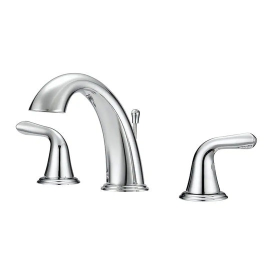
BATHROOM FAUCET
Purchase Date
1
ITEM #1233223
#1233224
#1233225
#1328817
MODEL #FW6BC002CP
#FW6BC002NP
#FW6BC002OB
#FW6BC002YP
Español p. 15
Publicidad
Tabla de contenido

Manuales relacionados para Project Source FW6BC002CP


Resumen de contenidos para Project Source FW6BC002CP
- Página 1 ITEM #1233223 #1233224 #1233225 #1328817 BATHROOM FAUCET MODEL #FW6BC002CP PROJECT SOURCE and PROJECT SOURCE & #FW6BC002NP Design are trademarks or registered trademarks #FW6BC002OB of LF, LLC. All rights reserved. #FW6BC002YP Español p. 15 ATTACH YOUR RECEIPT HERE Serial Number Purchase Date Questions, problems, missing parts? Before returning to your retailer, call our customer service department at 1-866-389-8827, 8 a.m.
-
Página 2: Package Contents
PACKAGE CONTENTS PART DESCRIPTION QUANTITY Hot Handle Rubber Washer (Preassembled) Metal Washer (Preassembled) Guide Washer (Preassembled) Rubber Spacer (Preassembled) Metal Spacer (Preassembled) Lock Nut (Preassembled) Faucet Connecting Hose Faucet Body Cold Handle Aerator Wrench DRAIN ASSEMBLY COMPONENTS Rubber Washer Large Rubber Washer Lock Nut Drain Body Plunger... -
Página 3: Safety Information
SAFETY INFORMATION • Follow these installation instructions carefully. Proper installation is the installer’s responsibility. • Failure to follow correct installation procedures can cause the faucet to become loose, which can result in serious injury. • The products should be installed by a locally licensed plumber. •... - Página 4 ASSEMBLY INSTRUCTIONS Turn off water supply. Remove existing faucet if necessary. Remove pre-assembled lock nut (G), metal spacer (F), and rubber spacer (E) from shank of faucet body (I). Place the spout (I) in the appropriate faucet hole of the sink (not included).
- Página 5 ASSEMBLY INSTRUCTIONS From underneath sink, replace rubber spacer (E) and metal spacer (F), tighten with lock nut (G). Note: The slotted space must face rear of sink. Remove pre-assembled guide washer (D), metal washer (C) and rubber washer (B) from shanks of hot handle (A) and cold handle (J).
- Página 6 ASSEMBLY INSTRUCTIONS Insert hot handle (A) and cold handle (J) through the appropriate faucet holes. From underneath sink, replace rubber washer (B) and metal washer (C) onto shanks of hot handle (A) and cold handle (J). Secure with guide washer (D). Remove caps from quick connect tubes.
- Página 7 ASSEMBLY INSTRUCTIONS 10. Attach faucet connecting hose (H) to connector receiver on hot handle (A), faucet body (I) and cold faucet (J). 11. Attach water supply lines (not included). Use one wrench to hold the faucet fitting and a second wrench to tighten the water supply line one quarter turn.
- Página 8 ASSEMBLY INSTRUCTIONS 13. Install drain body (DD) and rubber washer (AA) through top of sink (not included). Secure with large rubber washer (BB) and lock nut (CC). Note: Opening for ball rod (HH) must face towards rear of sink. 14. Insert plunger (EE). Note: Plastic loop on plunger (EE) facing rear of sink is in locked mode and plunger cannot be removed.
- Página 9 ASSEMBLY INSTRUCTIONS 16. Insert lift rod (FF) through faucet (I). From underneath the sink, connect the lift rod (FF) to the lift rod strap (GG) by pushing the button and inserting the lift rod (FF) all the way into the seated space of the lift rod strap (GG).
- Página 10 ASSEMBLY INSTRUCTIONS 19. Remove aerator from faucet (I). 20. Turn on both hot and cold water to flush out any debris and check for leaks around drain. 21. Replace aerator.
- Página 11 QUICK CONNECTOR REMOVAL Push quick connector housing upward. Hold clip and housing together and pull downward. CAUTION: Be careful in removal of quick connector to not cut hands.
- Página 12 CARE AND MAINTENANCE • Clean periodically with a soft cloth. Avoid abrasive cleaners, steel wool and harsh chemicals as these will dull the finish and void your warranty. TROUBLESHOOTING PROBLEM POSSIBLE CAUSE CORRECTIVE ACTION Leak from under handle. Retainer nut has come loose. Tighten the retainer nut.
-
Página 13: Replacement Parts List
REPLACEMENT PARTS LIST For replacement parts, call our customer service department at 1-866-389-8827, 8 a.m. - 8 p.m., EST, Monday - Friday. PART DESCRIPTION PART # Metal Handle – Cold A079171C Metal Handle – Hot A079171H Index Button A603A25 Handle Adapter A517156 Ceramic Disc Cartridge - Cold A507180N... -
Página 15: Grifo Para Baño
ARTÍCULO #1233223 #1233224 #1233225 #1328817 GRIFO PARA BAÑO MODELO #FW6BC002CP PROJECT SOURCE y PROJECT SOURCE & #FW6BC002NP Design son marcas o marcas registradas de LF, #FW6BC002OB LLC. Todos los derechos reservados. #FW6BC002YP ADJUNTE SU RECIBO AQUÍ Número de serie Fecha de compra ¿Preguntas, problemas, piezas faltantes? Antes de volver a la tienda, llame a nuestro... -
Página 16: Contenido Del Paquete
CONTENIDO DEL PAQUETE PIEZA DESCRIPCIÓN CANTIDAD Manija de agua caliente Arandela de goma (preensamblada) Arandela de metal (preensamblada) Arandela guía (preensamblada) Espaciador de goma (preensamblada) Espaciador de metal (preensamblada) Contratuerca (preensamblada) Manguera de conexión del grifo Cuerpo del grifo Manija de agua fría Llave para aireador COMPONENTES DEL ENSAMBLE DEL DESAGÜE Arandela de goma... -
Página 17: Información De Seguridad
INFORMACIÓN DE SEGURIDAD • Siga con atención las siguientes instrucciones de instalación. El instalador tiene la responsabilidad de realizar una instalación adecuada. • Si no sigue los procedimientos correctos de instalación, el grifo puede soltarse y causar lesiones graves. • Un plomero certificado debe instalar este producto. •... -
Página 18: Instrucciones De Ensamblaje
INSTRUCCIONES DE ENSAMBLAJE Interrumpa el suministro de agua. Si es necesario, retire el grifo existente. Retire la contratuerca preensamblada (G), el espaciador de metal (F) y el espaciador de goma (E) del vástago del cuerpo del grifo (I). 3. Coloque la boquilla (I) en el orificio correspondiente del grifo en el lavamanos (no se incluye). - Página 19 INSTRUCCIONES DE ENSAMBLAJE 4. Coloque un espaciador de goma (E) y un espaciador de metal (F) por debajo del lavamanos y aprieta con una contratuerca (G). NOTA: El espacio ranurado debe quedar frente a la parte posterior del lavabo. 5. Retire la arandela guía preensamblada (D), la aran-dela de metal (C) y la arandela de goma(B) de los vástagos de la manija de agua caliente (A) y la manija de agua fría (J).
- Página 20 INSTRUCCIONES DE ENSAMBLAJE 7. Inserte la manija de agua caliente (A) y la manija de agua fría (J) a través de los orificios correspondientes del grifo. 8. Desde debajo del lavabo, instale una arandela de goma (B) y una arandela de metal (C) en los ástagos de la manija de agua caliente (A) y la manija de agua fría (J).
- Página 21 INSTRUCCIONES DE ENSAMBLAJE 10. Fije la manguera de conexión del grifo (H) al receptor conector de la manija de agua caliente (A), el cuerpo del grifo (I) y la manija de agua fría (J). 11. Fije las tuberías de suministro de agua (no se incluyen).
- Página 22 INSTRUCCIONES DE ENSAMBLAJE 13. Instale el cuerpo del desagüe (DD) y la arandela de goma (AA) a través de la parte superior del lavabo (no se incluye). Asegure con la arandela de goma grande (BB) y la contratuerca (CC). NOTA: La abertura para la varilla de rótula debe quedar frente a la parte posterior del lavabo.
- Página 23 INSTRUCCIONES DE ENSAMBLAJE 16. Inserte la varilla de levantamiento (FF) en el grifo (I). Desde debajo del lavabo, conecte la varilla de levantamiento (FF) a la correa para la varilla de levantamiento (GG), para esto presione el botón y pase la varilla de levantamiento (FF) por completo hasta el espacio asentado de la correa para la varilla de levantamiento (GG).
- Página 24 INSTRUCCIONES DE ENSAMBLAJE 19. Retire el aireador del grifo (I). 20. Abra las manijas de agua caliente y fría, deje correr el agua para eliminar cualquier desecho y revise si hay fugas alrededor del desagüe. 21. Vuelva a colocar el aireador.
-
Página 25: Cuidado Y Mantenimiento
RETIRAR EL CONECTOR RÁPIDO 1. Jale la carcasa del conector rápido de la manguera hacia arriba. Mantenga el sujetador y la carcasa juntos y jale hacia abajo. ADVERTENCIA: Tenga cuidado al retirar el conector rápido para evitar cortarse las manos. CUIDADO Y MANTENIMIENTO •... -
Página 26: Garantía
GARANTÍA El fabricante garantiza que este grifo no presenta defectos en la mano de obra ni en los materiales presentes en el momento del transporte desde la fábrica durante un período limitado de por vida a partir de la fecha de compra. Esta garantía es válida solo para el comprador original. El fabricante acepta reparar dichos defectos sin cargo o, según nuestro criterio, reemplazar el grifo por un modelo comparable o superior. -
Página 27: Lista De Piezas De Repuesto
LISTA DE PIEZAS DE REPUESTO Para obtener piezas de repuesto, llame a nuestro Departamento de Servicio al Cliente al 1-866-389-8827, de lunes a viernes de 8 a.m. a 8 p.m., hora estándar del Este. PIEZA DESCRIPCIÓN PIEZA # Manija de metal: Fria A079171C Manija de metal: Caliente A079171H...