Publicidad
sauder.com
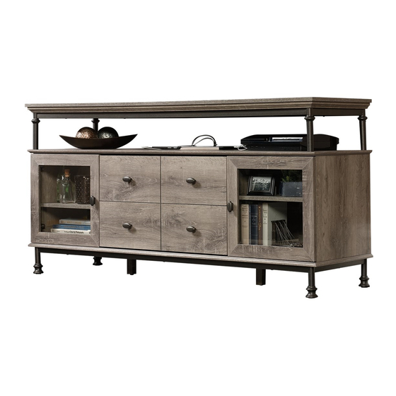
Entertainment Credenza
Canal Street Collection | Model 420494
Need help? Visit Sauder.com to view video assembly tips or chat with a live rep.
Prefer the phone? Call 1-800-445-1527.
Share your journey!
Entertaining what
entertains you.
NOTE: THIS INSTRUCTION
BOOKLET CONTAINS IMPORTANT
SAFETY INFORMATION.
PLEASE READ AND KEEP FOR
FUTURE REFERENCE.
English pg 1-28
Français pg 29-32
Español pg 33-36
Lot #: 396830
Date Purchased: __________________
01/25/17
Be sure to give us a ring before
making any returns. 1-800-445-1527
Publicidad
Tabla de contenido

Manuales relacionados para Sauder Credenza 420494


Resumen de contenidos para Sauder Credenza 420494
- Página 1 NOTE: THIS INSTRUCTION BOOKLET CONTAINS IMPORTANT SAFETY INFORMATION. PLEASE READ AND KEEP FOR Need help? Visit Sauder.com to view video assembly tips or chat with a live rep. FUTURE REFERENCE. Prefer the phone? Call 1-800-445-1527. English pg 1-28 Français pg 29-32 Español pg 33-36...
- Página 2 • Check the size and weight of your TV. Compare it to the diagram below – before you begin assembly! • This Sauder unit is designed for use with televisions weighing less than 70 pounds. Never use with a TV that weighs more.
-
Página 3: Part Identifi Cation
LEFT UPRIGHT (1) LOWER RIGHT DRAWER SIDE (1) LONG EXTENSION LONG EXTENSION SHORT EXTENSION SHORT EXTENSION RAIL - 2 SLIDE - 2 RAIL - 2 SLIDE - 2 (EXTENSION SET (EXTENSION SET SHOWN SEPARATED) SHOWN SEPARATED) 420494 www.sauder.com Page 3... - Página 4 7/8" MACHINE SCREW - 12 11/16" FLAT HEAD SCREW - 6 1/2" MACHINE SCREW - 16 1/2" LARGE PAN HEAD SCREW - 4 1/2" SMALL PAN HEAD SCREW - 24 1/2" FLAT HEAD SCREW - 8 Page 4 www.sauder.com 420494...
- Página 5 Look for this icon. It means a Step 1 video assembly tip is available at www.sauder.com/services/tips Assemble your unit on a carpeted fl oor or on the empty å carton to avoid scratching your unit or the fl oor. Fasten two LONG BRACES (E) to two SUPPORTS (D). Use å...
- Página 6 Step 2 Fasten the LONG BRACES (E) to the TOP (C). Use six å 1-3/8" FLAT HEAD SCREWS (18). Remember: Righty tighty. Lefty loosey. 1-3/8" FLAT HEAD SCREW (6 used in this step) Flat edge Page 6 www.sauder.com 420494...
- Página 7 Step 3 Turn eight ANGLED HEAD CAM SCREWS (3) into the å SHELF (F). Angled head 420494 www.sauder.com Page 7...
- Página 8 Fasten the SHELF (F) to the SUPPORTS (D). Use four å 1-3/16" MACHINE SCREWS (19). Insert eight WOOD DOWELS (6) into the holes in the SHELF (F) å as shown. Flat edge 1-3/16" MACHINE SCREW (4 used in this step) Page 8 www.sauder.com 420494...
- Página 9 Push eight LARGE HIDDEN CAMS (1) into the ENDS (A and B) å and UPRIGHTS (I and J). Arrow Arrow Hole The arrow in the HIDDEN CAM must point toward the hole in the edge of the board. 420494 www.sauder.com Page 9...
- Página 10 Use these holes to fasten the EXTENSION RAIL to the UPRIGHTS. Push the black lever down and pull the SLIDE from the RAIL. Open end SMALL 1/2" PAN HEAD SCREW Open end (6 used in this step) Page 10 www.sauder.com 420494...
- Página 11 NOTE: The EXTENSION SLIDES will be used later for the DRAWERS. å Use these holes to fasten the EXTENSION RAIL to the part. Push the black lever down and pull the SLIDE from the RAIL. SMALL 1/2" PAN HEAD SCREW (6 used in this step) 420494 www.sauder.com Page 11...
- Página 12 Surface with HIDDEN CAMS f a c S u r D E N H I D i t h o f a c S u r D E N H I D Page 12 www.sauder.com 420494...
- Página 13 ENDS (A and B) and UPRIGHTS (I and J). Fasten the BOTTOM (V) to the ENDS (A and B) and å UPRIGHTS (I and J). Use eight 2" FLAT HEAD SCREWS (16). 2" FLAT HEAD SCREW (8 used in this step) 420494 www.sauder.com Page 13...
- Página 14 å NOTE: Perforations have been provided for access å through the BACK. Carefully cut out the holes needed. This perforation should be cut out Perforation NAIL for the USB cord. (34 used in this step) Perforation Page 14 www.sauder.com 420494...
- Página 15 Step 11 Fasten the LONG BRACES (E) to the LEGS (W). Use eight å 1/2" MACHINE SCREWS (22). 1/2" MACHINE SCREW (8 used in this step) 420494 www.sauder.com Page 15...
- Página 16 BOTTOM (V). Use eight 1-3/8" FLAT HEAD SCREWS (18). Don't worry. It isn't Rome. This can be built Turn two CENTER LEGS (X) into the BOTTOM (V) until å in a day. they are tight. 1-3/8" FLAT HEAD SCREW (8 used in this step) Page 16 www.sauder.com 420494...
- Página 17 Step 13 Fasten the HINGES (11) to the DOORS (Z). Use eight 1/2" å FLAT HEAD SCREWS (25). 1/2” FLAT HEAD SCREW (8 used in this step) 420494 www.sauder.com Page 17...
- Página 18 Fasten the DOORS (Z) to the ENDS (A and B). Use the å screws in the HINGES. Fasten a KNOB (5) to each DOOR (Z). Use four 7/8" å MACHINE SCREWS (20). 7/8" MACHINE SCREW (4 used for the KNOBS) Page 18 www.sauder.com 420494...
- Página 19 Tighten the screws after making adjustments. To adjust the DOORS in or out (depth), loosen the mounting å screw one turn and move the DOORS in or out, as needed. Tighten the mounting screw after making adjustments. 420494 www.sauder.com Page 19...
- Página 20 ENDS (A and B) and UPRIGHTS (I and J). Set the ADJUSTABLE SHELVES (H) onto the METAL PINS. Insert the USB PORT (12) cord through the hole in the SHELF (F) å and then through the hole in the BACK (G). (8 used) Page 20 www.sauder.com 420494...
- Página 21 Turn six STRAIGHT HEAD CAM SCREWS (4) into the å LOWER DRAWER FRONT (T). Push six SMALL HIDDEN CAMS (2) into the large holes in the å DRAWER SIDES (P and R) and DRAWER BRACE (U). Straight head Arrow (6 used) 420494 www.sauder.com Page 21...
- Página 22 Fasten the DRAWER BACK (Q) to the DRAWER SIDES (P and R) and DRAWER BRACE (U). Use six 1-1/2" FLAT HEAD å SCREWS (17). NOTE: Be sure the DRAWER BOTTOM (S) inserts into the groove of the DRAWER BACK (Q). å Page 22 www.sauder.com 420494...
- Página 23 Fasten two KNOBS (5) to the DRAWER FRONT (T). Use å four 7/8" MACHINE SCREWS (20). 7/8" MACHINE SCREW Open end (4 used for the KNOBS) Open end 1/2" SMALL PAN HEAD SCREW (6 used in this step) 420494 www.sauder.com Page 23...
- Página 24 SIDE BRACKETS and LOWER DRAWER SIDES when this step is complete. Front Bracket Front Bracket Side Bracket 11/16" FLAT HEAD SCREW (6 used in this step) Front Bracket Side Bracket Side Bracket Front Bracket Page 24 www.sauder.com 420494...
- Página 25 FLAT HEAD SCREWS (17). F i n i s h r f a Notch 1-1/2" FLAT HEAD SCREW (14 used in this step) Angled edge F i n i s h r f a Angled edge 420494 www.sauder.com Page 25...
- Página 26 The HINGE BRACKET SET will allow the UPPER DRAWER å FRONT (O) to fl ip up for access to wireless components in the UPPER DRAWER as shown below. 1/2" LARGE PAN HEAD SCREW (4 used in this step) Front Bracket Page 26 www.sauder.com 420494...
- Página 27 Fasten the KNOBS (5) to the DRAWER FRONT (O). Use å four 7/8" MACHINE SCREWS (20). 7/8" MACHINE SCREW (4 used for the KNOBS) Open end Open end 1/2" SMALL PAN HEAD SCREW (6 used in this step) 420494 www.sauder.com Page 27...
- Página 28 And to celebrate, why not share your success story? 70 lbs. 31,75 kg 31,75 kg 22,68 22,68 70 lbs. 25 lbs. 40 lbs. 30 lbs. 25 lbs. 25 lbs. 25 lbs. 30 lbs. (12 used) To cover HIDDEN CAMS Page 28 www.sauder.com 420494...
-
Página 29: Liste De Pièces
élément et conserver le livret EXTRÉMITÉ DROITE ..........1 GRANDE EXCENTRIQUE pour future référence. ESCAMOTABLE ............8 EXTRÉMITÉ GAUCHE ..........1 Pour contacter Sauder PETITE EXCENTRIQUE ESCAMOTABLE .6 DESSUS ................1 en ce qui concerne cet VIS D'EXCENTRIQUE AVEC SUPPORT ................2 élément, faire référence TÊTE EN ANGLE ............8... - Página 30 ! schéma du haut. Faire attention car les pièces sont graissées. • Cette unité Sauder est conçue pour les téléviseurs pesant moins de 31,75 kg. Ne jamais utiliser avec des téléviseurs plus lourds. Fixer les LONGUES GLISSIÈRES D'EXTENSION (AA) sur les MONTANTS (I et J).
- Página 31 DE TIROIR (U). Utiliser six VIS TÊTE PLATE 38 mm (17). Fixer un BOUTON (5) à chaque PORTE (Z). Utiliser quatre VIS À MÉTAUX 22 mm (20). REMARQUE : S'assurer que le FOND DE TIROIR (S) s'encastre dans la rainure de l'ARRIÈRE DE TIROIR (Q). 420494 www.sauder.com Page 31...
- Página 32 Utiliser quatre GRANDES VIS TÊTE GOUTTE DE SUIF 13 mm (23). Le JEU DE CONSOLE DE CHARNIÈRE off riront le DEVANT DE TIROIR SUPÉRIEUR (O) à relevez pour accéder des composants sans fi ls dans le TIROIR SUPÉRIEUR comme il l’est indiqué ci-dessous. Page 32 www.sauder.com 420494...
-
Página 33: Credencia De Entretenimiento
EXCÉNTRICO ESCONDIDO PEQUEÑO ...6 EXTREMO IZQUIERDO ............1 pour future référence. BIELA DE EXCÉNTRICO CON PANEL SUPERIOR ..............1 Pour contacter Sauder CABEZA ANGULADA ..........8 en ce qui concerne cet SOPORTE ..................2 BIELA DE EXCÉNTRICO CON élément, faire référence RIOSTRA LARGA..............4... - Página 34 - antes de comenzar el ensamblaje! Fije los RIELES DE EXTENSIÓN LARGOS (AA) a los • Esta unidad Sauder está diseñada para ser usada con PARALES (I y J). Utilice seis TORNILLOS PEQUEÑOS DE televisores cuyo peso sea inferior a 31.75 Kg. Nunca la use para un CABEZA REDONDA de 13 mm (24).
- Página 35 Fije el DORSO DE CAJÓN (Q) a los LADOS DE CAJÓN (P y R) y a la RIOSTRA DE CAJÓN (U). Utilice seis TORNILLOS DE CABEZA PERDIDA de 38 mm (17). NOTA: Asegúrese que el FONDO DE CAJÓN (S) ajuste dentro de la ranura del DORSO DE CAJÓN (Q). 420494 www.sauder.com Page 35...
- Página 36 REDONDA de 13 mm (23). El JUEGO DE SOPORTE DE BISAGRA permitan la CARA DE CAJÓN SUPERIOR (O) se levanta para tener un acceso a los componentes inalámbricos en el CAJÓN SUPERIOR como se indica a continuación. Page 36 www.sauder.com 420494...
- Página 37 TOUJOURS décharger les tablettes et les tiroirs, en commençant par les surface supérieures, avant de déplacer le meuble. NE JAMAIS pousser ou tirer un meuble sur de la moquette. Demander à une autre personne de le soulever correctement pour le déplacer et/ou le repositionner. 420494 www.sauder.com Page 37...
- Página 38 SIEMPRE descargue los estantes y cajones, empezando con las superfi cies superiores, antes de moverlo. NUNCA empuje ni tire de los muebles sobre una alfombra. Obtenga que un amigo le ayude a levantarlo correctamente para moverlo y/o reposicionarlo. Page 38 www.sauder.com 420494...
-
Página 39: Garantie Limitée De 5 Ans
à compter de la date d'achat la première fois et qui sont signalés à Sauder dans les limites de couverture de la contre tout défaut de matériaux ou de fabrication des composantes de mobilier Sauder. - Página 40 Dear Valued Customer: So, how did it go? Thanks so much for choosing Sauder® furniture. I hope the Set a world record for speed? purchase and assembly process was a positive experience Feeling good about yourself? and you feel good about the furniture you just built. If you Nice.