Tabla de contenido
Publicidad
Idiomas disponibles
Idiomas disponibles
Enlaces rápidos
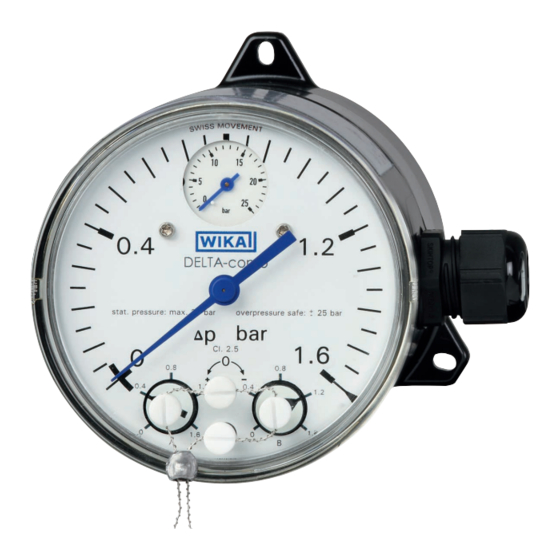
Differential pressure gauge with micro switches,
model DPGS40TA, with component testing
Differenzdruckmanometer
Typ DPGS40TA, mit Bauteilprüfung
Manomètre différentiel avec microrupteurs,
type DPGS40TA, avec test des composants
Manómetro diferencial con
Typ DPGS40TA, con prueba de componentes
Differential pressure gauge with integrated working pressure indication
and up to two micro switches, model DPGS40TA
Operating instructions
Betriebsanleitung
Mode d'emploi
Manual de instrucciones
mit Mikroschaltern,
microswitch,
DELTA-comb
EN
DE
FR
ES
Publicidad
Capítulos
Tabla de contenido

Manuales relacionados para WIKA DELTA-comb DPGS40TA


Resumen de contenidos para WIKA DELTA-comb DPGS40TA
- Página 1 Operating instructions Betriebsanleitung Mode d‘emploi Manual de instrucciones Differential pressure gauge with micro switches, model DPGS40TA, with component testing Differenzdruckmanometer mit Mikroschaltern, Typ DPGS40TA, mit Bauteilprüfung Manomètre différentiel avec microrupteurs, type DPGS40TA, avec test des composants Manómetro diferencial con microswitch, Typ DPGS40TA, con prueba de componentes DELTA-comb Differential pressure gauge with integrated working pressure indication...
- Página 2 55 - 80 Manual de instrucciones para manómetro diferencial, modelo DPGS40TA Seite 81 - 106 © 2015 WIKA Alexander Wiegand SE & Co. KG All rights reserved. / Alle Rechte vorbehalten. WIKA is a registered trademark in various countries. ® WIKA ist eine geschützte Marke in verschiedenen Ländern.
-
Página 3: Tabla De Contenido
Disposal ......28 Appendix 1: Germanischer Lloyd approval Appendix 2: SIL certificate Appendix 3: VdTÜV certificate „Flow 100:2006“ Appendix 4: Declaration of conformity Declarations of conformity can be found online at www.wika.com. WIKA operating instructions DPGS40TA with component testing... -
Página 4: General Information
Explanation of symbols WARNING! ... indicates a potentially dangerous situation that can result in serious injury or death, if not avoided. Information ... points out useful tips, recommendations and information for efficient and trouble-free operation. WIKA operating instructions DPGS40TA with component testing... -
Página 5: Safety
The instrument has been designed and built solely for the intended use described here, and may only be used accordingly. The manufacturer shall not be liable for claims of any type based on operation contrary to the intended use. WIKA operating instructions DPGS40TA with component testing... -
Página 6: Additional Instructions For Operation As A Flow Limiter In Accordance With Vdtüv Code Of Practice "Flow 100:2006
500 mm long. The requirements on the differential pressure lines in accordance with VdTÜV code of practice “Flow 100:2006” section 5.7.2.3 must be met. WIKA operating instructions DPGS40TA with component testing... -
Página 7: Functional Safety Of The Sil Version
IEC 61511 edition 1.0 Functional safety – Safety instrumented systems for the pro- cess industry ISO EN 13849-1:2008 Safety of machinery – Safety-related components of control systems – Part 1: General principles for design WIKA operating instructions DPGS40TA with component testing... - Página 8 The higher the safety integrity level of the safety-related system, the greater the probability that the safety function is executed. WIKA operating instructions DPGS40TA with component testing...
- Página 9 Number of cycles till 10 % of the components have failed dangerously Average number of operations per year β factor Factor for failure due to common causes, in terms of the interaction of several channels WIKA operating instructions DPGS40TA with component testing...
- Página 10 The specific parameters should always be considered with respect to the expected switching frequency. 2.3.6 Product label and safety marks S ... with VdTüV “Flow 100” option S ... with SIL option WIKA operating instructions DPGS40TA with component testing...
-
Página 11: Safety Function
Influence of the ambient temperature in the range -10 °C ... +70 °C ■ Influence of up to 259,835 load cycles ■ The total safety accuracy is -12 % ... +8 % of the measuring span for the differen- tial pressure. WIKA operating instructions DPGS40TA with component testing... -
Página 12: Operating Limits
Normally the proof test takes place every year, see certificates V 495.01/15 and V 405.02/15. 2.3.13 Proof test of the safety function Through a test of the entire safety function, check whether the switch is operating correctly. WIKA operating instructions DPGS40TA with component testing... - Página 13 (safety loop) should be initiated, in order to test whether the safety function of the system is still guaranteed. Function tests are intended to demonstrate the correct function of the whole safety-related system, including all instruments (sensor, logic unit, actuator). WIKA operating instructions DPGS40TA with component testing...
-
Página 14: Personnel Qualification
Take sufficient precautionary measures. WARNING! The maximum surface temperature of the instrument may not exceed the ignition temperature of flammable media. Take sufficient precautionary measures. WIKA operating instructions DPGS40TA with component testing... -
Página 15: Labelling, Safety Marks
Risk of burns! Potentially dangerous situation caused by hot surfaces. Due to the maximum permissible process temperature of 90 °C, measuring cells, adapters, valves or other attachment parts can reach a temperature of 90 °C. WIKA operating instructions DPGS40TA with component testing... -
Página 16: Specifications
1.4310 and separating diaphragm from FPM/FKM (option: NBR) Working pressure: Bourdon tube from Cu-alloy Transmission parts Stainless steel 1.4301, 1.4305, 1.4310, FPM/FKM (wetted) (option: NBR) Sealings (wetted) FPM/FKM (option: NBR) Copper alloy Movement WIKA operating instructions DPGS40TA with component testing... - Página 17 (option: Lead sealing of the settings) Weight approx. 1.3 kg For further specifications see the corresponding product label, WIKA data sheet and order documentation. For models with optional explosion protection read the “Additional information for hazardous areas (Ex i), models DPS40, DPGS40, DPGS40TA und DPGT40”, article number 14110818.
-
Página 18: Design And Function
(7). The assistant scales (8) simplify the setting of the switch points. ⊖ ⊕ 4.2 Scope of delivery Cross-check scope of delivery with delivery note. WIKA operating instructions DPGS40TA with component testing... -
Página 19: Transport, Packaging And Storage
Hazardous environments, flammable atmospheres ■ WARNING! Before storing the instrument, any residual media must be remo- ved. This is of particular importance if the medium is hazardous to health, e.g. caustic, toxic, carcinogenic, radioactive, etc. WIKA operating instructions DPGS40TA with component testing... -
Página 20: Commissioning, Operation
The instruments should be protected against coarse dirt and wide fluctuations in ambient temperature. For sealing the connections, use flat gaskets, lens-type sealing rings or WIKA ■ profile sealings. In order to orientate the gauge so that the on-site display can be read as well as possible, a connection with clamp socket or union nut should be used. - Página 21 With gaseous substances, the temperature may increase as a result of compression warming. In these cases it may be necessary to throttle the rate of change of pressure or reduce the permissible medium temperature. WIKA operating instructions DPGS40TA with component testing...
- Página 22 Pressure gauge above the tapping point Pressure gauge below the tapping point Dimensions in mm Cable gland M20 x 1.5 with 1 m cable WIKA operating instructions DPGS40TA with component testing...
-
Página 23: Electrical Connection
The mains connection lines to be provided must be dimensioned for maximum ■ instrument current supply and comply with IEC 227 or IEC 245. The instruments must be connected to the equipotential bonding of the plant. ■ For performance data see chapter 3 “Specifications” WIKA operating instructions DPGS40TA with component testing... - Página 24 For the safety circuit, which will switch off the heating if the steam generator falls below the minimum flow, only the normally open contact of the change-over contact should be connected (i.e. with Δp = 0 open circuit)! WIKA operating instructions DPGS40TA with component testing...
- Página 25 Seal the cable entry with the appropriate approved cable glands. ■ Cable gland Cable terminal box or angular connector Only use cable with a diameter of 7 ... 13 mm Install the connection cables securely. ■ WIKA operating instructions DPGS40TA with component testing...
-
Página 26: Commissioning
(with opened pressure compensating valve). Venting the measuring lines with liquid me- ■ dia and flushing of the measuring lines, in order to remove contamination. Shut-off valve Vent valve ⊖ side WIKA operating instructions DPGS40TA with component testing... -
Página 27: Panel Mounting Flange
Sequence of operations to dismount the measuring instrument with a running ■ process 1. Close the shut-off valve for the ⊕ and ⊖ media chamber 2. Open the vent valve 7.2 Panel mounting flange Panel WIKA operating instructions DPGS40TA with component testing... -
Página 28: Maintenance
9.3 Disposal Incorrect disposal can put the environment at risk. Dispose of instrument com- ponents and packaging materials in an environmentally compatible way and in accordance with the country-specific waste disposal regulations. WIKA operating instructions DPGS40TA with component testing... - Página 29 Entsorgung ..... . . 54 Anhang 1: Zulassung Germanischer Lloyd Anhang 2: SIL-Zertifikat Anhang 3: VdTÜV-Bescheinigung „Strömung 100“ Anhang 4: Konformitätserklärung Konformitätserklärungen finden Sie online unter www.wika.de. WIKA Betriebsanleitung DPGS40TA mit Bauteilprüfung...
-
Página 30: Allgemeines
… weist auf eine möglicherweise gefährliche Situation hin, die zum Tod oder zu schweren Verletzungen führen kann, wenn sie nicht gemieden wird. Information … hebt nützliche Tipps und Empfehlungen sowie Informationen für einen effizienten und störungsfreien Betrieb hervor. WIKA Betriebsanleitung DPGS40TA mit Bauteilprüfung... -
Página 31: Sicherheit
Steuerung von Filtern, Kompressoren und Pumpen. Das Gerät ist ausschließlich für den hier beschriebenen bestimmungsgemäßen Verwendungszweck konzipiert und konstruiert und darf nur dementsprechend verwendet werden. Ansprüche jeglicher Art aufgrund von nicht bestimmungsgemäßer Verwendung sind ausgeschlossen. WIKA Betriebsanleitung DPGS40TA mit Bauteilprüfung... -
Página 32: Zusatzhinweise Für Den Einsatz Als Strömungsbegrenzer Gemäß Vdtüv Merkblatt „Strömung 100:2006
Blockventilen ist darauf zu achten, dass die Wirkdruckleitung zwischen Blockven- til und dem Wirkdruckaufnehmer als Bestandteil des Schaltgliedes mindestens 500 mm lang ist. Die Anforderungen an Wirkdruckleitungen gemäß VdTÜV Merkblatt „Strömung 100:2006“ Abschnitt 5.7.2.3 müssen eingehalten werden. WIKA Betriebsanleitung DPGS40TA mit Bauteilprüfung... -
Página 33: Funktionale Sicherheit Der Sil-Ausführung
Funktionale Sicherheit sicherheitsbezogener elektrischer/ele- ktronischer/programmierbarer elektronischer Systeme IEC 61511 Edition 1.0 Funktionale Sicherheit – Sicherheitstechnische Systeme für die Prozessindustrie ISO EN 13849-1:2008 Sicherheit von Maschinen – Sicherheitsbezogene Teile von Steuerungen – Teil 1: Allgemeine Gestaltungsleitsätze WIKA Betriebsanleitung DPGS40TA mit Bauteilprüfung... - Página 34 Integrity Level (SIL 1 bis SIL 4). Jeder Level entspricht einem Wahrscheinlichkeitsbereich mit welchem ein sicherheitsbezogenes System die festgelegten Sicherheitsfunktionen anforderungsgemäß ausführt. Je höher der Safety Integrity Level der sicherheitsbezo- genen Systeme ist, umso größer die Wahrscheinlichkeit, dass die Sicherheitsfunktion ausgeführt wird. WIKA Betriebsanleitung DPGS40TA mit Bauteilprüfung...
- Página 35 Mittlere Zeit bis zum Auftreten eines gefahrbringenden Ausfalls Anzahl von Zyklen, bis 10 % der Komponenten gefährlich ausgefa- llen sind Mittlere Anzahl der jährlichen Betätigungen β-Faktor Faktor für den Ausfall infolge gemeinsamer Ursachen, im Hinblick auf das Zusammenwirken mehrerer Kanäle WIKA Betriebsanleitung DPGS40TA mit Bauteilprüfung...
- Página 36 Einsatzfall mit den Anforderungen der Applikation zu verglei- chen. Die spezifischen Kenngrößen sind immer in Hinblick auf die ange- nommene Schalthäufigkeit zu betrachten. 2.3.6 Typenschild und Sicherheitskennzeichnungen S ... mit Option VdTüV „Strömung 100“ S ... mit Option SIL WIKA Betriebsanleitung DPGS40TA mit Bauteilprüfung...
- Página 37 Grundgenauigkeit (Messabweichung, Linearitätsfehler) ■ Einfluss der Umgebungstemperatur im Bereich -10 °C ... +70 °C ■ Einfluss von bis zu 259.835 Lastwechseln ■ Die Gesamtsicherheitsgenauigkeit beträgt -12 % … +8 % der Messspanne für den Differenzdruck. WIKA Betriebsanleitung DPGS40TA mit Bauteilprüfung...
- Página 38 PFD -Wert. Üblicherweise wird von einer Wiederholungs- prüfung von 1 Jahr ausgegangen, siehe Zertifikate V 495.01/15 und V 495.02/15. 2.3.13 Test der Sicherheitsfunktion Beim Test der gesamten Sicherheitsfunktion prüfen, ob die Schalter ordnungsge- mäß funktionieren. WIKA Betriebsanleitung DPGS40TA mit Bauteilprüfung...
- Página 39 Austausch des Gerätes muss ein Funktionstest der gesamten Si- cherheitsfunktion (Sicherheitsloop) gestartet werden, um zu prüfen, ob die Sicherheitsfunktion des Systems immer noch gewährleistet ist. Die Funktionstests dienen dazu, die einwandfreie Funktion der Sicherheitseinrichtung SIS im Zusammenwirken aller Komponenten (Sensor, Logikeinheit, Aktor) nachzuweisen. WIKA Betriebsanleitung DPGS40TA mit Bauteilprüfung...
-
Página 40: Personalqualifikation
Vorschriften beachtet werden. WARNUNG! Messstoffreste in ausgebauten Messgeräten können zur Gefähr- dung von Personen, Umwelt und Einrichtung führen. Ausreichende Vorsichtsmaßnahmen ergreifen. WARNUNG! Die maximale Oberflächentemperatur des Gerätes darf die Zündtemperatur brennbarer Messstoffe nicht überschreiten. Ausreichende Vorsichtsmaßnahmen ergreifen. WIKA Betriebsanleitung DPGS40TA mit Bauteilprüfung... -
Página 41: Beschilderung, Sicherheitskennzeichnungen
Vor Montage und Inbetriebnahme des Gerätes unbedingt die Betriebsanleitung lesen! Verbrennungsgefahr! Möglicherweise gefährliche Situation durch heiße Oberflächen. Aufgrund der maximal zulässigen Prozesstemperatur von 90 °C können Messzellen, Anschlussstücke, Ventile oder sonstige Anbauteile eine Temperatur von 90 °C erreichen. WIKA Betriebsanleitung DPGS40TA mit Bauteilprüfung... -
Página 42: Technische Daten
Achsabstand 26 mm Messglieder Differenzdruck: Druckfedern aus CrNi-Stahl 1.4310 und Trenn- (messstoffberührt) membrane aus FPM/FKM (Option: NBR) Betriebsdruck: Rohrfeder aus Cu-Legierung Übertragungsteile CrNi-Stahl 1.4301, 1.4305, 1.4310, FPM/FKM (Option: NBR) (messstoffberührt) Dichtungen FPM/FKM (Option: NBR) (messstoffberührt) Zeigerwerk Kupferlegierung WIKA Betriebsanleitung DPGS40TA mit Bauteilprüfung... - Página 43 Elektrischer Anschluss Kabelverschraubung M20 x 1,5 mit 1 m freiem Kabel 1) I max. = 1,4 A für Ausführung nach VdTÜV Merkblatt „Strömung 100“ Weitere technische Daten siehe jeweiliges Typenschild, WIKA-Datenblatt und Bestellunterlagen. Für Typen mit optionalem Explosionsschutz „Zusatzinformation für explosionsgefährdete Bereiche (Ex i), Typen DPS40, DPGS40, DPGS40TA und...
-
Página 44: Aufbau Und Funktion
Stützflächen (6) erreicht. Die Schaltpunktverstellung erfolgt über die frontseitig zugänglichen Einstells- chrauben (7). Die Hilfsskalen (8) erleichtern die Schaltpunkteinstellung. ⊖ ⊕ 4.2 Lieferumfang Lieferumfang mit dem Lieferschein abgleichen. WIKA Betriebsanleitung DPGS40TA mit Bauteilprüfung... -
Página 45: Transport, Verpackung Und Lagerung
Explosionsgefährdete Umgebung, entzündliche Atmosphären ■ WARNUNG! Vor der Einlagerung des Gerätes müssen alle ggf. anhaftenden Messstoffreste entfernt werden. Dies ist besonders wichtig, wenn das Medium gesundheitsgefährdend ist, wie z. B. ätzend, giftig, krebserregend, radioaktiv, usw. WIKA Betriebsanleitung DPGS40TA mit Bauteilprüfung... -
Página 46: Inbetriebnahme, Betrieb
örtliche Anzeige am besten ablesen lässt, ist ein Anschluss mit Spannmuffe oder Überwurfmutter zu empfehlen. Beim Ein- und Ausschrauben dürfen die Geräte nicht am Gehäuse angezogen werden, sondern nur an den Schlüsselflächen des Anschlussstutzens! Wandmontage Befestigung über drei angegossene Befestigungslaschen WIKA Betriebsanleitung DPGS40TA mit Bauteilprüfung... - Página 47 Geräten selbst abhängig, sondern hauptsächlich von der jeweiligen Messstofftemperatur! Bei gasförmigen Stoffen kann sich die Temperatur durch Kompressionswärme erhöhen. In solchen Fällen muss ggf. die Druckänderungsgeschwindigkeit gedrosselt bzw. die zulässige Messstofftemperatur reduziert wer- den. WIKA Betriebsanleitung DPGS40TA mit Bauteilprüfung...
- Página 48 (feucht) siert Beispiele Kondensat siedende „Flüssig- trockene feuchte Luft Wasserdampf Flüssigkei- gase“ Luft Rauchgase Manometer oberhalb des Entnahme- stutzens Manometer unterhalb des Entnah- mestutzens Abmessungen in mm Kabelverschraubung M20 x 1,5 mit 1 m Kabel WIKA Betriebsanleitung DPGS40TA mit Bauteilprüfung...
-
Página 49: Elektrischer Anschluss
Die vorgesehenen Netzanschlussleitungen müssen für die größte Stromaufna- ■ hme des Gerätes bemessen sein und IEC 227 oder IEC 245 entsprechen. Die Geräte sind in den Potenzialausgleich der Anlage mit einzubeziehen. ■ Leistungsdaten siehe Kapitel 3 „Technische Daten“ WIKA Betriebsanleitung DPGS40TA mit Bauteilprüfung... - Página 50 2. Kontakt 1. Kontakt Kabelanschlussdose Für den Sicherheitsstromkreis, der bei Unterschreiten des Min- destdurchflusses die Beheizung des Dampferzeugers abschalten soll, darf nur der Schließer des Umschaltkontaktes angeschlossen werden (d.h. der bei Δp = 0 offene Kreis)! WIKA Betriebsanleitung DPGS40TA mit Bauteilprüfung...
- Página 51 Anschlussleitungen müssen für den Umgebungstemperaturbereich der ■ Applikation geeignet sein. Kabeleinführung mit den entsprechend zugelassenen Kabelverschraubungen ■ dicht verschließen. Kabelverschraubung Kabelanschlussdose bzw. Winkelsteckverbinder Nur Kabel mit Durchmesser 7 ... 13 mm verwenden Anschlusskabel fest verlegen. ■ WIKA Betriebsanleitung DPGS40TA mit Bauteilprüfung...
-
Página 52: Inbetriebnahme
Prozess sowie Vermeidung einseitiger Überdruckbelastung während der Anfahr- bzw. Betriebsphase (bei geöffnetem Druckausgleichsventil). Entlüftung der Messleitungen bei flüssigen ■ Messstoffen und Spülung der Messleitun- Absperrventil Entlüftungs- ⊖ ventil -Seite gen, um Verunreinigungen zu entfernen. WIKA Betriebsanleitung DPGS40TA mit Bauteilprüfung... -
Página 53: Befestigungsrand Für Schalttafelmontage
■ 1. Druckausgleichsventil öffnen 2. Absperrventil der ⊕- und ⊖-Messstoffkammer schließen Arbeitsgangfolge zur Demontage des Messgerätes bei laufenden Prozess ■ 1. Absperrventil der ⊕- und ⊖-Messstoffkammer schließen 2. Entlüftungsventil öffnen 7.2 Befestigungsrand für Schalttafelmontage Schalttafel WIKA Betriebsanleitung DPGS40TA mit Bauteilprüfung... -
Página 54: Wartung
Mitarbeiter und Umwelt vor Gefährdung durch anhaftende Messstoffreste zu schützen. 9.3 Entsorgung Durch falsche Entsorgung können Gefahren für die Umwelt entstehen. Geräte- komponenten und Verpackungsmaterialien entsprechend den landesspezifis- chen Abfallbehandlungs- und Entsorgungsvorschriften umweltgerecht entsor- gen. WIKA Betriebsanleitung DPGS40TA mit Bauteilprüfung... - Página 55 ..... . 80 Appendix 1: Agrément Germanischer Lloyd Appendix 2: Certificat SIL Appendix 3: Certificate VdTÜV „Flux 100:2006“ Appendix 4: Déclaration de conformité Déclarations de conformité disponibles sur www.wika.fr. WIKA mode d‘emploi manomètre DPGS40TA avec test des composants...
-
Página 56: Généralités
évitée. Information ... met en exergue les conseils et recommandations utiles de même que les informations permettant d'assurer un fonctionne- ment efficace et normal. WIKA mode d‘emploi manomètre DPGS40TA avec test des composants... -
Página 57: Sécurité
Ces instruments sont conçus et construits exclusivement pour une utilisation con- forme à l'usage prévu décrit ici, et ne doivent être utilisés qu'à cet effet. Aucune réclamation ne peut être recevable en cas d'utilisation non conforme à l'usage prévu. WIKA mode d‘emploi manomètre DPGS40TA avec test des composants... -
Página 58: Instructions Complémentaires Pour Une Utilisation Comme Limiteur De Flux En Conformité Avec Le Code De Pratique Vdtüv, "Flux 100 :2006
500 mm. Les exigences concernant les lignes de pression différentielle en accord avec le code de pratique VdTÜV “Flux 100 :2006” section 5.7.2.3 doivent être respectées. WIKA mode d‘emploi manomètre DPGS40TA avec test des composants... -
Página 59: Sécurité Fonctionelle De La Version Sil
Sécurité fonctionnelle – Systèmes de sécurité actifs pour les procédés industriels ISO EN 13849-1:2008 Sécurité des installations – Composants de systèmes de contrôle ayant trait à la sécurité – Partie 1 : Principes généraux de conception WIKA mode d‘emploi manomètre DPGS40TA avec test des composants... - Página 60 Tolérance d'erreur matériel Capacité d'une unité fonctionnelle à continuer l'exécution de la fonc- tion demandée lorsque des erreurs ou des déviations se produisent. WIKA mode d‘emploi manomètre DPGS40TA avec test des composants...
- Página 61 Nombre de cycles avant que 10 % des composants aient failli de manière dangereuse Nombre moyen d'opérations par an Facteur β Facteur pour une erreur due à des causes courantes, en termes d'interaction de plusieurs canaux WIKA mode d‘emploi manomètre DPGS40TA avec test des composants...
- Página 62 Les paramètres spécifiques doivent toujours être considérés dans le respect de la fréquence de commutation attendue. 2.3.6 Plaque signalétique et marquages de sécurité S ... avec VdTüV option “Flux 100” S ... avec option SIL WIKA mode d‘emploi manomètre DPGS40TA avec test des composants...
-
Página 63: Fonction De Sécurité
Influence de la température ambiante sur l'étendue -10 °C ... +70 °C ■ Influence de jusqu'à 259.835 cycles de charge ■ La précision de sécurité totale est de -12 % ... +8 % de l'intervalle de mesure pour la pression différentielle. WIKA mode d‘emploi manomètre DPGS40TA avec test des composants... -
Página 64: Limites De Fonctionnement
495.01/15 et V 405.02/15. 2.3.13 Test de vérification de la fonction de sécurité Au moyen d'un test de la fonction de sécurité dans son ensemble, vérifiez si le commutateur fonctionne correctement. WIKA mode d‘emploi manomètre DPGS40TA avec test des composants... -
Página 65: Informations Concernant La Détermination De Paramètres Relatifs À La Sécurité
Les tests de fonction ont pour but de prouver que la totalité du système de sécurité fonctionne correc- tement, ainsi que tous les instruments (capteur, unité logique, actionneur). WIKA mode d‘emploi manomètre DPGS40TA avec test des composants... -
Página 66: Qualification Du Personnel
Prendre des mesures de sécurité suffisantes. AVERTISSEMENT ! La température de surface maximum admissible de l'instrument ne doit pas dépasser la température d'inflammation de fluides inflammables. Prendre des mesures de sécurité suffisantes. WIKA mode d‘emploi manomètre DPGS40TA avec test des composants... -
Página 67: Etiquetage, Marquages De Sécurité
En raison de la température de process maximum admissible de 90 °C, les cellules de mesure, adaptateurs, robinets ou autres élé- ments de montage peuvent atteindre des températures de 90 °C. WIKA mode d‘emploi manomètre DPGS40TA avec test des composants... -
Página 68: Spécifications
Pression de service : tube manométrique en alliage de cuivre Pièces de transmission Acier inox 1.4301, 1.4305, 1.4310, FPM/FKM (option : NBR) (contact avec fluide) Joints d'étanchéité (en FPM/FKM (option : NBR) contact avec le fluide) WIKA mode d‘emploi manomètre DPGS40TA avec test des composants... - Página 69 1,3 kg Pour de plus amples spécifications, voir la plaque signalétique correspondante, la fiche technique WIKA et la documentation de commande. Pour les types avec protection contre les explosions, lire les “Informations com- plémentaires concernant les zones explosives (Ex i), types DPS40, DPGS40, DPGS40TA et DPGT40”, numéro d'article 14110818.
-
Página 70: Conception Et Fonction
Les échelles auxiliaires (8) facilitent le réglage des points de seuil. ⊖ ⊕ 4.2 Détail de la livraison Comparer le détail de la livraison avec le bordereau de livraison. WIKA mode d‘emploi manomètre DPGS40TA avec test des composants... -
Página 71: Transport, Emballage Et Stockage
Enlever tous les restes de fluides adhérents avant l'entreposage de l'instrument. Ceci est particulièrement important lorsque le fluide représente un danger pour la santé, comme p. ex. des substances corrosives, toxiques, cancérogènes, radioactives etc. WIKA mode d‘emploi manomètre DPGS40TA avec test des composants... -
Página 72: Mise En Service, Utilisation
Pour sceller les connexions, utiliser des joints d'étanchéité plats, des bagues ■ d'étanchéité de type lentille ou des joints à écrasement WIKA. Pour orienter le manomètre de sorte que l'affichage local puisse être lu aussi bien que possi- ble, une connexion avec un manchon de serrage ou un écrou à chapeau doit être utilisée. - Página 73 Avec les substances gazeuses, la température pourrait augmenter à la suite d'un échauffement de compression. Dans ces cas-là, il peut s'avérer nécessaire d'accélérer le taux de changement de pression ou de réduire la température du fluide admissible. WIKA mode d‘emploi manomètre DPGS40TA avec test des composants...
- Página 74 Manomètre au-dessus du point de mesure Manomètre en-dessous du point de mesure Dimensions en mm Presse-étoupe M20 x 1,5 avec 1 m de câble WIKA mode d‘emploi manomètre DPGS40TA avec test des composants...
-
Página 75: Raccordement Électrique
à CEI 227 ou CEI 245. Les instruments sont à inclure dans la compensation de potentiel de ■ l'installation. Pour données de performance voir chapitre 3 “Spécifications” WIKA mode d‘emploi manomètre DPGS40TA avec test des composants... -
Página 76: Consignes De Sécurité Pour L'installation
Pour le circuit de sécurité, qui va éteindre le chauffage si le gé- nérateur de vapeur tombe sous la valeur minimum de flux, seul le contact normalement ouvert du contact inverseur doit être raccor- dé (c'est-à-dire avec Δp = 0 circuit ouvert) ! WIKA mode d‘emploi manomètre DPGS40TA avec test des composants... - Página 77 Sceller l'entrée de câble avec les presse-étoupes homologués adéquats. ■ Presse-étoupe Boîtier de raccordement ou connecteur coudé Utiliser seulement un câble ayant un diamètre de 7 à 13 mm Installer les câbles de raccordement en toute sécurité. ■ WIKA mode d‘emploi manomètre DPGS40TA avec test des composants...
-
Página 78: Mise En Service
Mise à l'atmosphère des lignes de mesure ■ Robinet avec des fluides liquides et un rinçage des Robinet d’isolement de mise à lignes de mesure pour supprimer la contami- côté ⊖ l'atmosphère nation. WIKA mode d‘emploi manomètre DPGS40TA avec test des composants... -
Página 79: Collerette Avant Pour Montage Panneau
1. Fermer le robinet d’isolement pour les chambres de fluide ⊕ et ⊖ 2. Ouvrir la soupape de mise à l'atmosphère 7.2 Collerette avant pour montage panneau Panneau WIKA mode d‘emploi manomètre DPGS40TA avec test des composants... -
Página 80: Entretien
Une mise au rebut inadéquate peut entraîner des dangers pour l'environnement. Eliminer les composants des instruments et les matériaux d'emballage con- formément aux prescriptions nationales pour le traitement et l'élimination des déchets et aux lois de protection de l'environnement en vigueur. WIKA mode d‘emploi manomètre DPGS40TA avec test des composants... - Página 81 Devolución ..... . 106 Eliminación de residuos ....106 Declaraciones de conformidad puede encontrar en www.wika.es. WIKA manual de instrucciones DPGS40TA con prueba del componente...
-
Página 82: Información General
... señala una situación probablemente peligrosa que puede cau- sar la muerte o lesiones graves si no se evita. Información ... marca consejos y recomendaciones útiles así como informacio- nes para una utilización eficaz y libre de fallos. WIKA manual de instrucciones DPGS40TA con prueba del componente... -
Página 83: Seguridad
El instrumento ha sido diseñado y construido únicamente para la finalidad aquí descrita y debe utilizarse en conformidad a la misma. No se admite ninguna reclamación debido a una utilización no conforme a lo previsto. WIKA manual de instrucciones DPGS40TA con prueba del componente... -
Página 84: Indicaciones Adicionales Para El Uso Como Limitador De Corriente Conforme A La Ficha Técnica Vdtüv "Corriente 100:2006
500 mm de longitud como mínimo. Deben respetarse los requisitos en cuanto a las tuberías de presión diferencial conforme a la ficha técnica VdTÜV “corriente 100:2006” apartado 5.7.2.3. WIKA manual de instrucciones DPGS40TA con prueba del componente... -
Página 85: Otra Documentación Relativa Al Instrumento
Seguridad funcional – Sistemas de seguridad para la industria de procesos ISO EN 13849-1:2008 Seguridad de las máquinas – Partes de los sistemas de mando relativas a la seguridad – Parte 1: Principios generales para el diseño WIKA manual de instrucciones DPGS40TA con prueba del componente... -
Página 86: Abreviaturas
Proporción de los fallos peligrosos detectados por las pruebas diagnósticas automáticas online. Tolerancia a error del hardware Tolerancia a errores del hardware; capacidad de una unidad funcio- nal de continuar ejecutando una función solicitada si existen errores o desviaciones. WIKA manual de instrucciones DPGS40TA con prueba del componente... - Página 87 Cantidad de ciclos hasta que un 10% de los componentes presen- tan un fallo peligroso. Promedio de accionamientos anuales. Factor β Factor para el fallo como resultado de causas conjuntas, respecto a la interacción de varios canales. WIKA manual de instrucciones DPGS40TA con prueba del componente...
-
Página 88: Uso Conforme A Lo Previsto En Aplicaciones De Seguridad
Los parámetros específicos se han de contemplar siempre con respecto a la frecuencia de funcionamiento asumida. 2.2.7 Placa de características y marcajes de seguridad S ... con opción VdTüV "corriente 100" S ... con opción SIL WIKA manual de instrucciones DPGS40TA con prueba del componente... -
Página 89: Limitación De Los Modos De Funcionamiento
Influencia de la temperatura ambiente en el rango -10 °C ... +70 °C ■ Influencia de hasta 259.835 ciclos ■ La exactidud de seguridad total es de -12 % … +8 % del intervalo de medida para la presión diferencial. WIKA manual de instrucciones DPGS40TA con prueba del componente... -
Página 90: Límites De Aplicación
V 495.01/15 y V 495.02/15. 2.2.14 Test de la función de seguridad Durante el test de la función de seguridad completa se comprueba el funciona- miento correcto de los interruptores. WIKA manual de instrucciones DPGS40TA con prueba del componente... -
Página 91: Indicaciones Para La Determinación De Índices En Materia De Seguridad
Las pruebas funcionales verifican el funcionamiento perfecto del sistema de seguridad SIS en interacción con todos los componentes (sensor, unidad lógica, actuador). WIKA manual de instrucciones DPGS40TA con prueba del componente... -
Página 92: Cualificación Del Personal
Tomar las medidas de precaución adecuadas. ¡ADVERTENCIA! La temperatura máxima de la superficie del instrumento no debe ser superior a la temperatura de ignición de medios inflammables. Tomar las medidas de precaución adecuadas. WIKA manual de instrucciones DPGS40TA con prueba del componente... -
Página 93: Rótulos, Marcajes De Seguridad
Debido a una temperatura de proceso máx. admisible de 90 °C, las células de medida, los racores, las válvulas o otras piezas de montaje pueden alcanzar una temperatura de 90 °C. WIKA manual de instrucciones DPGS40TA con prueba del componente... -
Página 94: Datos Técnicos
1.4310 y membrana de separación de FPM/FKM (opción: NBR) Presión de trabajo: Muelle tubular de aleación de cobre Piezas de transmisión (en Acero inoxidable 1.4301, 1.4305, 1.4310, FPM/FKM contacto con el medio) (opción: NBR) WIKA manual de instrucciones DPGS40TA con prueba del componente... -
Página 95: Contacto Eléctrico
1) I max. = 1,4 A para la versión según folleto „Strömung 100“ de VdTÜV Para consultar más datos técnicos véase la placa de identificación correspon- diente, la hoja técnica de WIKA y la documentación de pedido. Para modelos con protección antiexplosiva opcional, leer la “información adicional para atmósferas potencialmente explosivas (Ex i), modelos DPS40, DPGS40,... -
Página 96: Diseño Y Función
Las escalas auxiliares (8) facilitan el ajuste del punto de conmutación. ⊖ ⊕ 4.2 Alcance del suministro Comparar mediante el albarán si se han entregado todas las piezas. WIKA manual de instrucciones DPGS40TA con prueba del componente... -
Página 97: Transporte, Embalaje Y Almacenamiento
Antes de almacenar el instrumento, eliminar todos los restos de medios adheridos. Esto es especialmente importante cuando el medio es nocivo para la salud, como p. ej. cáustico, tóxico, cancerí- geno, radioactivo, etc. WIKA manual de instrucciones DPGS40TA con prueba del componente... -
Página 98: Puesta En Servicio, Funcionamiento
Para sellar las conexiones deben utilizarse juntas planas, juntas lenticulares o ■ juntas perfiladas WIKA. Para poner el instrumento en la posición que propor- cionará la mejor lectura, se recomienda una conexión con un manguito tensor o tuerca tapón. ¡Al enroscar y desenroscar, debe apretarse aplicando la llave... - Página 99 En estos casos, hay que disminuir la velocidad de cambio de pre- sión o reducir la temperatura admisible del medio si fuera necesa- rio. WIKA manual de instrucciones DPGS40TA con prueba del componente...
-
Página 100: Sustancias A Medir Líquidas Sustancias A Medir Gaseosas
Gases de agua ción combustión Manómetro encima del manguito de toma Manómetro debajo del manguito de toma Dimensiones en mm Prensaestopa M20 x 1,5 con 1 m de cable WIKA manual de instrucciones DPGS40TA con prueba del componente... -
Página 101: Conexión Eléctrica
IEC 227 o IEC 245. Integrar los instrumentos en la conexión equipotencial de la instalación. ■ Para rendimiento véase el capítulo 3 “Datos técnicos” WIKA manual de instrucciones DPGS40TA con prueba del componente... -
Página 102: Indicaciones De Seguridad Para La Instalación
(es decir, el circuito abierto en Δp = 0)! WIKA manual de instrucciones DPGS40TA con prueba del componente... - Página 103 Sellar las entradas de cable con racores debidamente aprobados. ■ Prensaestopas Caja de conexión o conector angular Utilizar únicamente cables de diámetro 7 ... 13 mm Tender el cable de conexión de forma fija. ■ WIKA manual de instrucciones DPGS40TA con prueba del componente...
-
Página 104: Puesta En Servicio
(con válvula compensadora de presión abierta). Purgado de las tuberías de medición en Válvula de Válvula de ■ ventilación cierre, lado ⊖ medios líquidos y enjuague de las mismas para eliminar impurezas. WIKA manual de instrucciones DPGS40TA con prueba del componente... -
Página 105: Borde De Fijación Para Montaje En Cuadro De Distribución
1. Cerrar la válvula de cierre de las cámaras del medio ⊕ y ⊖ 2. Abrir la válvula de ventilación 7.2 Borde de fijación para montaje en cuadro de distribución Cuadro de distribución WIKA manual de instrucciones DPGS40TA con prueba del componente... -
Página 106: Mantenimiento
Una eliminación incorrecta puede provocar peligros para el medio ambiente. Eliminar los componentes de los instrumentos y los materiales de embalaje conforme a los reglamentos relativos al tratamiento de residuos y eliminación vigentes en el país de utilización. WIKA manual de instrucciones DPGS40TA con prueba del componente... -
Página 107: Appendix 1: Germanischer Lloyd Approval
Appendix 1: Germanischer Lloyd approval WIKA operating instructions DPGS40TA with component testing... - Página 108 Appendix 1: Germanischer Lloyd approval WIKA operating instructions DPGS40TA with component testing...
-
Página 109: Appendix 2: Sil Certificate
Appendix 2: SIL certificate WIKA operating instructions DPGS40TA with component testing... - Página 110 Appendix 2: SIL certificate WIKA operating instructions DPGS40TA with component testing...
-
Página 111: Appendix 3: Vdtüv Certificate „Flow 100:2006
Appendix 3: VdTÜV certificate “Flow 100” WIKA operating instructions DPGS40TA with component testing... -
Página 112: Appendix 4: Declaration Of Conformity
Appendix 4: Declaration of conformity WIKA operating instructions DPGS40TA with component testing... - Página 113 Appendix 4: Declaration of conformity WIKA operating instructions DPGS40TA with component testing...
- Página 114 WIKA operating instructions DPGS40TA with component testing...
- Página 115 WIKA operating instructions DPGS40TA with component testing...
- Página 116 WIKA subsidiaries worldwide can be found online at www.wika.com. WIKA-Niederlassungen weltweit finden Sie online unter www.wika.de. La liste des filiales WIKA dans le monde se trouve sur www.wika.fr. Sucursales WIKA en todo el mundo puede encontrar en www.wika.es. WIKA Alexander Wiegand SE & Co. KG Alexander-Wiegand-Straße 30...