Tabla de contenido
Publicidad
Idiomas disponibles
Idiomas disponibles
Enlaces rápidos
Publicidad
Tabla de contenido

Manuales relacionados para dirna Bergstrom bycool blue line FLAT RENAULT


Resumen de contenidos para dirna Bergstrom bycool blue line FLAT RENAULT
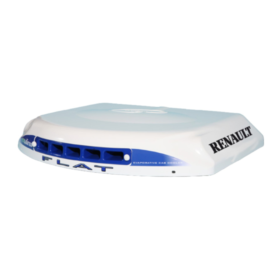
- Página 1 Air conditioning for vehicles FLAT Instrucciones de Montaje Spanish Mounting Instructions English Instructions de Montage French Montageanweisungen German Istruzioni di Montaggio Italian 220AA70007...
-
Página 2: Recomendaciones Para El Montaje
12 meses. Al instalar el equipo evaporativo en el techo se debe proteger la parte superior de la cabina con un paño ó dirna Bergstrom, s.l. • queda exenta de manta protectora para evitar posibles arañazos. Al instalar Bycool Flat en el techo hay que tener en responsabilidad si se producen averías que procedan... - Página 3 FLAT Air conditioning for vehicles Desmontar tapa escotilla, los elementos de fijación y entregar éstos al cliente (*). Quitar los residuos sobrantes adheridas al techo antes de pegar la junta EPDM.
- Página 4 FLAT Air conditioning for vehicles Pegue la junta EPDM alrededor del hueco de escotilla (mirar el detalle para cortar los bordes finales de unión de la junta). 15 mm COMO CORTAR LA JUNTA EPDM PARA EVITAR FILTRACIÓN DE AGUA EN LA CABINA A- Pegar la junta, manteniendo 100 mm de papel protector por cada lado.
- Página 5 FLAT Air conditioning for vehicles EXTERIOR CABINA: Posicionar el Bycool en el hueco de la escotilla. Escotilla INTERIOR CABINA: Base Bycool 5 mm Roscar 5 mm aproximadamente (4) espárragos Espárrago 8/125x100 o 120, la medida se elegirá tras presentar los soportes de sujección y teniendo Soporte en cuenta que los espárragos deben sobresalir de los mismos por la parte inferior unos 10...
- Página 6 FLAT Air conditioning for vehicles Colocar (2) soportes sujeción, con (1) arandela y (1) tuerca autoblocante M8, sin llegar a apretar. Roscar 10 mm (4) espárragos M6 x 55 o 80, donde se indica, dependiendo de la altura (A) del esquema del punto 9. Colocar (1) arandela Ø6 de goma, (1) arandela plana Ø6 ala ancha y (1) tuerca M6, sobre cada uno de los espárragos de M6.
- Página 7 FLAT Air conditioning for vehicles Colocar (1) tuerca M6 sin apretar en cada espárrago. Pegar los canalizadores al panel interior de distribución de aire utilizando LOCTITE superglue 3 o similar, para facilitar el montaje del conjunto y asegurar los flujos de aire fríos por las lumbreras.
- Página 8 FLAT Air conditioning for vehicles Colocar el panel interior de distribución de aire en los espárragos anteriores con (1) arandela M6 ala ancha y (1) tuerca M6 en cada espárrago. Apretar tuercas hasta que los canalizadores hagan tope en goma espuma superior del equipo.
- Página 9 FLAT Air conditioning for vehicles Fijar los soportes de sujección apretando las tuercas hasta el apriete de la junta de EPDM exterior del equipo entre 3 y 6mm. Importante: Para evitar posibles filtraciones de agua al interior de la cabina se debe asegurar el apriete de la junta EPDM con la base del Comprobar la Bycool tal y como se indica en el esquema.
- Página 10 FLAT Air conditioning for vehicles Colocar tuerca M6 (A) tras la tuerca de fijación del panel interior de distribución de Base Bycool aire en cada espárrago. Colocar hexágonos M6 roscandolo hasta que quede 1 mm por Exágono sujección consola encima del tapizado. Desenroscar tuercas M6 (A) de este punto hasta que haga tope con los Tapizado hexágonos y apretar contra estos.
-
Página 11: Vista Explosionada Hasta La Fijación De Los Soportes
FLAT Air conditioning for vehicles Vista explosionada hasta la fijación de los soportes Espárrago Arandela de goma ø 7 M8 x125 x 100 ó 120 Arandela plana ø 8 ala ancha Tuerca M8 Techo cabina Tuerca M8 Arandela plana ø 6 ala ancha Junta de EPDM de 25 mm. -
Página 12: Operaciones A Realizar Para El Montaje Del Depósito De Agua
FLAT Air conditioning for vehicles Conectar cajas cableados y tubos, por la parte caja 4 vías trasera del Bycool según se indica. caja 2 vías Tubo retorno Tubo impulsión bomba Tubo con cinta blanca Operaciones a realizar para el montaje del depósito de Agua: Posicionar soporte depósito en la parte baja más adecuada de la zona trasera de la cabina. - Página 13 FLAT Air conditioning for vehicles Marcar y taladrar Ø 9 en cabina teniendo en cuenta que la posición vertical del soporte. Mínimo (6) taladros de sujeción. Colocar tuercas remache de M6 y fijar el soporte con tornillos 6/100x30. 6/100x30 allen (*) - En los casos que no apoye en parte Arandela grower Ø...
- Página 14 FLAT Air conditioning for vehicles A continuación conectar tubo de bomba (X) a depósito y fijar depósito (eligiendo mejor posición del tapón de llenado, derecha o izquierda, para facilitar el mismo) con soportes suministrados. El soporte con resalte se coloca en caso de montar el depósito con el tapón de llenado (Y) al lado izquierdo.
- Página 15 FLAT Air conditioning for vehicles Colocar tapón en el depósito, cortar a 100mm; intercalar “T” y conectar a ésta el tubo de menor sección, marcado con cinta blanca y cerciorarse que el radio de la curva sea suficiente para evitar estrangulamientos.
- Página 16 FLAT Air conditioning for vehicles Tubo de desagüe (*) Manera correcta de instalación, donde el tubo de desagüe tenga caída evitando bucles y estrangulamientos, para facilitar la caída de agua al depósito. (**) Manera incorrecta. No realizar. (***) NO CORTAR cableado sobrante y sujetarlo (enrollado), detrás del depósito de agua.
-
Página 17: Instrucciones Detalladas Sobre La Instalación Del Cableado De Alimentación
FLAT Air conditioning for vehicles Instrucciones detalladas sobre la instalación del cableado de alimentación Cableado de alimentación 1- Llevar el cable de alimentación del equipo hasta la batería del vehículo, pegando los soportes de plástico en la parte posterior de la cabina y fijandolo con bridas; después con la cabina abatida pasar el cable por la parte inferior de la misma sujetándolo con abrazaderas y tornillos M4;... -
Página 18: Esquema Eléctrico
FLAT Air conditioning for vehicles Esquema eléctrico CONTROL ELECTRÓNICO RELE BOMBA CONTACTO BOMBA FLOTADOR BOMBA DE AGUA BATERÍA SOPLADOR HORIZONTAL CENTRÍFUGO BOMBA AGUA FLOTADOR... - Página 19 When • Dirna Bergstrom, s.l. will not be held responsible installing Bycool Flat in the ceiling, bear in mind for any faults arising from inappropriate handling or...
- Página 20 FLAT Air conditioning for vehicles Dismount hatch cover and the fastening items and give these to the customer (*). Remove any excess material stuck to the roof before sticking the EPDM seal.
- Página 21 FLAT Air conditioning for vehicles Stick the EPDM seal around the hatch gap (check the drawing for cutting the edges of the gasket seal ). 15 mm HOW TO CUT THE EPDM SEAL TO AVOID WATER LEAKING INTO THE CAB A- Stick the seal, keeping 100 mm of protection paper on each side.
- Página 22 FLAT Air conditioning for vehicles OUTER CAB: Place the Bycool in the hatch gap. Hatch INSIDE CAB: Bycool Base 5 mm Thread (4) stud bolts 8/125x100 or 120 mm Stud bolt approximately 5 mm, choose the measurement after placing the fastening supports and bearing Support in mind that the stud bolts should protrude from the bottom part by some 10 mm.
- Página 23 FLAT Air conditioning for vehicles Place (2) fastening supports, with (1) washer and (1) self-locking nut M8, do not tighten. Thread (4) stud bolts M6 x 55 or 80, 10 mm where indicated, depending on the height of (A) in drawing for point 9. Place (1) rubber washer Ø6, (1) wide-flanged washer Ø6 and (1) M6 nut, on each one of the M6 stud bolts.
- Página 24 FLAT Air conditioning for vehicles Place (1) M6 nut on each stud bolt do not tighten. Attach the ducts to the interior air distribution panel using LOCTITE Superglue 3 or similar, in order to facilitate the assembly of the equipment and ensure the flows of cold air through the louvres.
- Página 25 FLAT Air conditioning for vehicles Position the interior air distribution panel on the front studs with (1) M6 wide-rimmed washer and (1) M6 nut on each stud. Tighten the nuts until the duct units come up against the unit’s upper foam. Important: The channellers must meet the rubber to avoid air leaks.
- Página 26 FLAT Air conditioning for vehicles Fasten the fastening supports by tightening the nut until the outer EPDM seal tightening of the equipment is between 3 and 6mm. Important: To avoid possible water leaks into the inside of the cab the EPDM seal tightening must be adjusted with the base of the Bycool as indicated in the drawing.
- Página 27 FLAT Air conditioning for vehicles Position nut M6 (A) after the fastening nut of the interior air distribution panel on each stud. Bycool Base Screw on M6 hexagons up to 1 mm above the upholstery. Unscrew the M6 nuts (A) of this Hexagonal fastening console point until they come into contact with the hexagons, and tighten against them.
- Página 28 FLAT Air conditioning for vehicles Exploded view to support fastening Stud bolt Rubber washer ø 7 M8 x125 x 100 or 120 Wide-flanged flat washer ø 8 M8 Nut Cab roof M8 Nut Wide-flanged flat washer ø 6 25 mm. EPDM Seal. Fastening support Wide-flanged flat washer M8 Self-locking nut...
- Página 29 FLAT Air conditioning for vehicles Connect cabling boxes and pipes, through the 4-way box rear part of the Bycool as indicated. 2-way box Return pipe Pump impulsion pipe Pipes marked with white tape Operations to be carried out to assemble the Water tank: Place tank support on the most suitable lower part of the rear area of the cab.
- Página 30 FLAT Air conditioning for vehicles Mark and drill Ø 9 on the cab bearing in mind the vertical position of the support. Minimum (6) fastening drill holes. Place M6 rivet nuts and fix the support with M6/100x30 screws. Allen screw 6/100x30 (*) –...
- Página 31 FLAT Air conditioning for vehicles Then connect the pump pipe (x) to the tank and fasten tank (choosing the best position for the filling plug, right or left, to enable this) with supports supplied. The support with the projection is placed, if the tank is assembled with the filling plug, (Y) to the left-hand side.
- Página 32 FLAT Air conditioning for vehicles Place the filler plug in the tank, cut to 100mm; insert “T” and connect the pipe with the smaller diameter to this, mark with white tape and check that the curve radius is big enough to avoid constriction. Connect sheathed wiring to the evaporative boxes and water inlet pipe.
- Página 33 FLAT Air conditioning for vehicles Drain pipe (*) Correct installation method, where the drain pipe has a slope avoiding loops and constrictions, enabling the water to drain into the tank. (**) Incorrect method. Do not do this. (***) DO NOT CUT surplus cable and attach it (wound), behind the water tank.
- Página 34 FLAT Air conditioning for vehicles Detailed instructions about power supply installation Power Cable 1- Run the power cable of the equipment to the vehicle battery, sticking the plastic supports on the rear part of the cab and attaching it with cable ties; then with the cab folded forward pass the cable through the lower area and fasten it with clamps and M4 screws;...
-
Página 35: Electronic Control
FLAT Air conditioning for vehicles Electric drawing ELECTRONIC CONTROL PUMP RELAY PUMP CONTACT HORIZONTAL WATER PUMP BATTERY CENTRIFUGAL FLOAT BLOWER WATER PUMP FLOAT... -
Página 36: Avertissements
être remplacée tous les 12 mois. cabine avec un chiffon ou un tissu protecteur pour • dirna Bergstrom, s.l. est exempte de toute éviter les éraflures. Lorsque le Bycool Flat est fixé responsabilité en cas de pannes dues à une au plafond, il faut savoir que, normalement, les manipulation ou à... - Página 37 FLAT Air conditioning for vehicles Démonter le couvercle écoutille, les éléments de fixation et les remettre au client (*). Enlever les résidus restants adhérés au toit avant de coller le joint EPDM.
- Página 38 FLAT Air conditioning for vehicles Collez le joint EPDM autour du creux de l´écoutille (regarder le détail pour couper les bords d´union du joint). 15 mm COMMENT COUPER LE JOINT EPDM POUR ÉVITER LA FILTRATION DE L´EAU DANS LA CABINE A- Coller le joint, tout en maintenant 100 mm de papier protecteur de chaque côté.
- Página 39 FLAT Air conditioning for vehicles EXTERIEUR CABINE: Placer le Bycool dans le creux de l´écoutille. Écoutille INTERIEUR CABINE: Base Bycool 5 mm Visser (4) perches 8/125x100 ou 120 environ 5 Perche mm, la mesure sera choisie après présenter les supports de fixation et en tenant compte que Support les perches doivent ressortir environ 10 mm de ceux-ci par la partie inférieure.
- Página 40 FLAT Air conditioning for vehicles Placer (2) supports de fixation, avec (1) rondelle et (1) écrou autobloquant M8, sans serrer. Visser (4) perches M6 x 55 ou 80 10 mm, à l´endroit indiqué, selon la hauteur (A) sur le schéma du point 9. Placer (1) rondelle Ø6 en caoutchouc, (1) rondelle plate Ø6 surface large et (1) écrou M6, sur chacune des perches de M6.
- Página 41 FLAT Air conditioning for vehicles Placer (1) écrou M6 sans serrer sur chaque perche. Coller les canalisateurs sur le panneau intérieur de distribution en utilisant du LOCTITE superglue 3 ou similaire, afin de faciliter le montage de l´ensemble et assurer les flux d´air froid par les ouvertures.
- Página 42 FLAT Air conditioning for vehicles Placer le panneau intérieur de distribution d’air dans les goujons précédents avec (1) rondelle M6 surface large et (1) écrou M6 sur chaque goujon. Serrer les écrous jusqu’à ce que les canalisateurs heurtent le caoutchouc mousse supérieur de l´équipement.
- Página 43 FLAT Air conditioning for vehicles Fixer les supports de fixation en serrant les écrous jusqu´à serrer le joint de EPDM extérieur de l´équipement entre 3 et 6mm. Important: Pour éviter de possibles filtrations d´eau à l´intérieur de la cabine, vous devez assurer la fixation du joint EPDM avec la Vérifier la base du Bycool comme il est indiqué...
- Página 44 FLAT Air conditioning for vehicles Placer un écrou M6 (A) après l’écrou de fixation du panneau intérieur de distribution Base Bycool d’air dans chaque goujon. Placer les hexagones M6 en vissant jusqu’à ce qu’il reste 1 mm au- Hexagone fixation console dessus de la tapisserie.
- Página 45 FLAT Air conditioning for vehicles Vue agrandie jusqu´à fixation des supports Perche Rondelle en caoutchouc ø 7 M8 x125 x 100 ou 120 Rondelle plate ø 8 surface large Écrou M8 Toit cabine Écrou M8 Rondelle plate ø 6 surface plate Joint de EPDM de 25 mm.
- Página 46 FLAT Air conditioning for vehicles Boîte 4 voies Connecter les boîtes de câblages et tuyaux par la partie arrière du Bycool, en suivant les Boîte 2 voies indications. Tuyau retour Tuyau impulsion pompe Tuyaux marqués avec bande blanche Opérations à suivre pour le montage du réservoir d´Eau: Placer le support réservoir dans la partie basse la plus convenable de la zone arrière de la...
- Página 47 FLAT Air conditioning for vehicles Marquer et percer Ø 9 dans la cabine en tenant compte de la position verticale du support. Minimum (6) perçages de fixation. Placer des écrous rivet de M6 et fixer le support avec des vis 6/100x30. 6/100x30 allen (*) –...
- Página 48 FLAT Air conditioning for vehicles Connecter ensuite le tuyau de pompe (X) au réservoir et fixer le dépôt (en choisissant la meilleure position du bouchon de remplissage, droite ou gauche, pour le faciliter) avec des supports fournis. Le support avec ressortant se place en cas de montage du réservoir avec le bouchon de remplissage (Y) sur le côté...
- Página 49 FLAT Air conditioning for vehicles Placer le bouchon dans le réservoir, couper à 100 mm; intercaler “T” et connecter le tuyau avec la plus petite section à celle-ci, marquer avec une bande blanche et s´assurer que le rayon de la courbe est suffisant pour éviter des étranglements.
- Página 50 FLAT Air conditioning for vehicles Tuyau d´écoulement (*) Installation correcte, qui permet que le tuyau d´écoulement ait une tombée tout en évitant les boucles et les étranglements, afin de faciliter la tombée de l´eau dans le réservoir. (**) Installation incorrecte. Ne pas réaliser. (***) NE PAS COUPER le câblage restant et le fixer (enroulé) derrière le réservoir d´eau.
- Página 51 FLAT Air conditioning for vehicles Instructions détaillées sur l´installation du câblage d´alimentation Câblage d´alimentation 1- Porter le câble d´alimentation jusqu´à la batterie du véhicule, en collant les supports en plastique sur la partie supérieure de la cabine et en les fixant avec des brides; ensuite, avec la cabine abattue, passer le câble à travers la partie inférieure de celle-ci en le fixant avec des anneaux et des vis M4;...
-
Página 52: Schéma Électrique
FLAT Air conditioning for vehicles Schéma électrique CONTROLE ELECTRONIQUE RELAIS POMPE CONTACT POMPE FLOTTEUR POMPE A EAU BATTERIE SOUFFLEUR HORIZONTAL CENTRIFUGE POMPE A EAU FLOTTEUR... - Página 53 Teil der Kabine mit einem Tuch oder einer Decke gegen eventuelle Kratzer • dirna Bergstrom, s.l. übernimmt keine Haftung geschützt werden. Bei der Installation des Bycool bei Schäden durch unsachgemäßen Umgang mit Flat an der Decke ist zu berücksichtigen, dass die...
- Página 54 FLAT Air conditioning for vehicles Lukendeckel, und Befestigungsteile abnehmen und dem Kunden übergeben (*). Bevor die EPDM-Dichtung verklebt wird, überschüssige Reste von der Decke entfernen.
- Página 55 FLAT Air conditioning for vehicles Kleben Sie die EPDM –Dichtung um die Lukenöffnung (beachten Sie die Hinweise zum Beschneiden der Abschlussverbindungskanten der Dichtung) 5 mm SO WIRD DIE EPDM-DICHTUNG BESCHNITTEN, UM DAS EINSICKERN VON WASSER IN DAS FAHRERHAUS ZU VERMEIDEN: A- Dichtung so verkleben, dass 100 mm Schutzpapier an jeder Seite überstehen.
- Página 56 FLAT Air conditioning for vehicles FAHRERHAUS, AUSSEN: Bycoolanlage Lukenöffnung positionieren. Luke FAHRERHAUS, INNEN: Bycoolgrundplatte 5 mm (4) Stiftschrauben 8/125x100 oder 120 Stiftschraube ca. 5 mm eindrehen. Das Maß wird nach der Positionierung der Befestigungsstützen Stütze gewählt, wobei zu berücksichtigen ist, dass die Stiftschrauben nach unten 10 mm überstehen 10 mm müssen...
- Página 57 FLAT Air conditioning for vehicles (2) Befestigungsstützen mit (1) Scheibe und (1) selbstblockierende M8-Mutter eindrehen, jedoch ohne sie anzuziehen. (4) Stiftschrauben M6 x 55 oder 80 10 mm an der angegebenen Stelle eindrehen, und zwar von der Höhe (A) der Skizze, Punkt 9. (1) Gummischeibe Ø6,(1) Breitflanschscheibe Ø6 und (1) Mutter M6 auf jede der...
- Página 58 FLAT Air conditioning for vehicles An jeder Stiftschraube (1) Mutter M6 einlegen, ohne diese jedoch anzuziehen. Kabelführungen mit LOCTITE Superglue 3 oder ähnlich an die innere Luftverteilertafel ankleben, um die Montage der Einheit zu erleichtern und die Kaltluftströme durch die Durchlassgitter zu garantieren.
- Página 59 FLAT Air conditioning for vehicles Innere Luftverteilertafel an den vorgenannten Stiftschrauben mit jeweils (1) Breitflansch- Unterlegscheibe M6 und (1) Mutter M6 anbringen. Muttern anziehen, Kabelführungen am oberen Schaumgummi der Anlage anliegen. Wichtig: Führungen müssen Schaumgummi anschlagen, Luftleckagen zu vermeiden. Bycool-Grundplatte Schaumstoff EPDM- Dichtung...
- Página 60 FLAT Air conditioning for vehicles Bringen Sie die Befestigungsstützen an, in- dem Sie die Muttern anziehen, bis die EPDM- Außendichtung 3-6 mm auf der Anlage fest- sitzt. Wichtig: Als Schutz gegen eventuelle Einsic- kerungen von Wasser in das Fahrerhausinnere muss die EPDM-Dichtung, wie auf der Skizze Zusammendrückung angegeben, auf der Grundplatte der Bycool- der EPDM-Dichtung...
- Página 61 FLAT Air conditioning for vehicles Eine Mutter hinter Befestigungsmutter inneren Bycool-Grundplatte Luftverteilertafel an allen Stiftschrauben anbringen. Sechskant-Verbindungsmuttern Sechskantrschraube f. M6 eindrehen, bis sie 1 mm über dem Bezug Konsolenbefestigung herausstehen. Muttern M6 (A) dieses Punkts Polsterung herausschrauben, bis sie an die Sechskant- Verbindungsmuttern anstoßen, und gegen diese anziehen.
- Página 62 FLAT Air conditioning for vehicles Übersichtsbild bis zur befestigung der stützen Stiftschraube Gummischeibe ø 7 M8 x125 x 100 oder 120 Breitflanschflachscheibe ø 8 M8 Mutter Fahrerhausdecke M8 Mutter Breitflanschflachscheibe ø 6 EPDM-Dichtung 25 mm Befestigungsstütze Breitflanschflachscheibe Selbstblockierende Mutter M8 Übersichtsbild bis zur befestigung der konsolen Gummischeibe Ø6 Breitflanschflachscheibe ø...
- Página 63 FLAT Air conditioning for vehicles 4-Wege-Kasten Verkabelte und verrohrte Kästen von hinten, dargestellt, Bycool-Anlage 2-Wege-Kasten befestigen. Rücklaufrohr Pumpendruckrohr Mit weißem Streifen markierte Rohre Vorgehensweise zum Einbau des Wasserbehälters: Behälterstütze an einem geeigneten, ziemlich weit unten liegenden Punkt im hinteren Bereich des Fahrerhauses positionieren.
- Página 64 FLAT Air conditioning for vehicles Ø 9 im Fahrerhaus markieren und bohren. Beachten dabei senkrechte Position Stütze. Mindestens Befestigungsbohrungen. Nietmuttern M6 anbringen und Stütze mit Schrauben 6/100x30 befestigen. Inbusschraube (*) – In Fällen, in denen die Stütze nicht 6/100x30 Growerscheibe Ø 6 auf einem glatten Teil aufliegt, 10 mm Flachscheibe Ø...
- Página 65 FLAT Air conditioning for vehicles Anschließend Pumpenrohr (X) an Behälter anschließen und Behälter (wählen Sie dazu die optimale Position des Füllstopfens, rechts oder links, um die Füllung zu erleichtern) mit den mitgelieferten Stützen befestigen. Die Stütze mit Absatz wird verwendet, wenn der Behälter mit dem Füllstopfen (Y) auf der linken Seite eingebaut wird.
- Página 66 FLAT Air conditioning for vehicles Stopfen in den Behälter einsetzen, auf 100 mm zuschneiden, “T” einschieben und daran das Rohr mit dem kleineren Querschnitt anschließen, Dieses ist mit weißem Streifen gekennzeichnet. Vergewissern Sie sich, dass die Biegung ausreicht, um Drosselungen zu vermeiden.
- Página 67 FLAT Air conditioning for vehicles Entwässerungsrohr (*) Korrekte Installation erfolgt an dem Punkt, an dem das Entwässerungsrohr Gefaälle aufweist, um Schleifen und Drosselungen zu vermeiden und den Wasserzulauf in den Behälter zu erleichtern. (**) Falsch. Darf so nicht ausgeführt werden. (***) Überschüssige Verkabelung AUF KEINEN FALL ABSCHNEIDEN, sondern (zusammengerollt) hinter dem Wasserbehälter...
- Página 68 FLAT Air conditioning for vehicles Detaillierte Anweisungen zur Installation der Versorgungskabel Versorgungs- verkabelung Versorgungskabel der Anlage bis zur Fahrzeugbatterie führen und dabei die Kunststoffstützen innen im Fahrerhaus aufkleben und mit Flanschen befestigen. Anschließend das Kabel bei heruntergeklapptem Fahrerhaus durch das Innere des Fahrerhaus führen und mit Schellen und M4-Schrauben befestigen, bis zur Batterie mit Schellen.
- Página 69 FLAT Air conditioning for vehicles Elektrisches schaltschema CONTROLE PUMPENRELAIS ELEKTRONIKSTEUERUNG PUMPENKONTAKT SCHWIMMER WASSERPUMPE BATTERIE DOPPELRADIALGEBLÄSE WASSERPUMPE SCHWIMMER...
- Página 70 Quando si installa il dispositivo evaporativo sul tetto sostituire ogni 12 mesi. bisogna proteggere la parte superiore della cabina con un panno o una coperta di protezione, per evitare dirna Bergstrom, s.l. eventuali graffi. Quando si installa Bycool Flat • non assume alcuna sul tetto bisogna considerare che, normalmente, le responsabilità...
- Página 71 FLAT Air conditioning for vehicles Smontare coperchio tettuccio, gli elementi di fissaggio e consegnarli al cliente (*). Togliere i residui in eccesso attaccati al soffitto prima di incollare la guarnizione EPDM.
- Página 72 FLAT Air conditioning for vehicles Incollare la guarnizione EPDM intorno al vano del tettuccio (osservare i particolari per tagliare i bordi finali di unione della guarnizione). 15 mm COME TAGLIARE LA GUARNIZIONE EPDM PER EVITARE LA FILTRAZIONE D’ACQUA NELLA CABINA A- Incollare la guarnizione, mantenendo 100 mm di carta protettiva su ogni lato.
- Página 73 FLAT Air conditioning for vehicles ESTERNO CABINA: Collocare il Bycool nel vano del tettuccio. Tettuccio INTERNO CABINA: Base Bycool 5 mm Avvitare circa 5 mm (4) viti prigioniere Vite prigioniera 8/125x100 o 120, la misura verrà scelta dopo aver collocato i supporti di fissaggio e Supporto considerando che le viti prigioniere devono fuoriuscire dagli stessi dalla parte inferiore di...
- Página 74 FLAT Air conditioning for vehicles Collocare (2) supporti di fissaggio, con (1) rondella e (1) dado autobloccante M8, senza stringere. Filettare 10 mm (4) viti prigioniere M6 X 55 o 80, dove indicato, a seconda dell’altezza (A) dello schema del punto 9. Collocare (1) rondella Ø6 di gomma, (1) rondella piana Ø6 larga e (1) dado M6, su ciascuna delle viti prigioniere M6.
- Página 75 FLAT Air conditioning for vehicles Collocare (1) dado M6 senza stringere in ogni vite prigioniera. Incollare i canalizzatori al pannello interno di distribuzione dell’aria con LOCTITE superglue 3 o un prodotto simile, per agevolare il montaggio dell’insieme e assicurare il deflusso dell’aria fredda dalle bocchette.
- Página 76 FLAT Air conditioning for vehicles Montare il pannello interno di distribuzione dell’aria sulle viti prigioniere anteriori con (1) rondella M6 a testa larga e (1) dado M6 su ogni vite prigioniera. Stringere i dadi finché i canalizzatori non sono a battuta sulla gommapiuma superiore dell’impianto.
- Página 77 FLAT Air conditioning for vehicles Fissare i supporti di fissaggio stringendo i dadi fino al serraggio della guarnizione di EPDM esterna del dispositivo tra 3 e 6 mm. Importante: Per evitare possibili infiltrazioni d’acqua all’interno della cabina bisogna garantire il serraggio della guarnizione EPDM Verificare la con la base del Bycool come indicato nello compressione della...
- Página 78 FLAT Air conditioning for vehicles Inserire il dado M6 (A) sul dado di fissaggio del pannello interno di distribuzione dell’aria Base Bycool su ogni vite prigioniera. Inserire i perni esagonali M6 e avvitarli fino a lasciarli a 1 mm Esagono fissaggio consolle al di sopra della tappezzeria.
- Página 79 FLAT Air conditioning for vehicles Vista esplosa fino al fissaggio dei supporti Vite prigioniera Rondella di gomma ø 7 M8 x125 x 100 o 120 Rondella piana Ø 8 larga Dado M8 Soffitto cabina Dado M8 Rondella piana Ø 6 larga Guarnizione di EPDM di 25 mm.
- Página 80 FLAT Air conditioning for vehicles Scatola a 4 vie Collegare casse cablaggi e tubi, dalla parte posteriore del Bycool come viene indicato. Scatola a 2 vie Tubo ritorno Tubo mandata pompa Tubi segnati con nastro bianco Operazioni da effettuare per il montaggio del serbatoio d’acqua: Collocare il supporto del serbatoio nella parte bassa più...
- Página 81 FLAT Air conditioning for vehicles Segnare e forare Ø 9 in cabina considerando la posizione verticale del supporto. Minimo (6) fori di fissaggio. Collocare dadi rivetto M6 e fissare il supporto con viti 6/100x30. 6/100x30 a brugola (*) - nei casi in cui non poggi su una parte Rondella grower Ø6 liscia, collocare un separatore di 10 mm e una Rondella piana Ø6...
- Página 82 FLAT Air conditioning for vehicles Quindi collegare il tubo della pompa (X) al serbatoio e fissarlo (scegliendo la posizione migliore per il tappo di riempimento, destra o sinistra, per agevolare lo stesso) con i supporti forniti. Il supporto con aggetto viene collocato nel caso in cui si monti il deposito con il tappo di riempimento (Y) sul lato sinistro.
- Página 83 FLAT Air conditioning for vehicles Collocare il tappo nel serbatoio, tagliare a 100 mm; intercalare “T” e collegare alla stessa un tubo di sezione inferiore, segnato con del nastro bianco e assicurarsi che il raggio della curva sia sufficiente per evitare strangolamenti.
- Página 84 FLAT Air conditioning for vehicles Tubo di scarico (*) Modalità corretta di installazione, dove il tubo di scarico ha una certa inclinazione ed evita nodi e strangolamenti per agevolare la caduta dell’acqua verso il serbatoio. (**) Modalità non corretta. Non fare così. (***) NON TAGLIARE il cablaggio in eccesso e fissarlo (avvolto), dietro al serbatoio d’acqua.
- Página 85 FLAT Air conditioning for vehicles Istruzioni dettagliate sull’installazione del cablaggio di alimentazione Cablaggio di alimentazione 1- Portare il cavo di alimentazione del dispositivo fino alla batteria del veicolo, incollando i supporti di plastica nella parte posteriore della cabina e fissandolo con flange; successivamente, con la cabina ribaltata, passare il cavo dalla parte inferiore della stessa, fissandolo con ghiere e viti M4;...
-
Página 86: Schema Elettrico
FLAT Air conditioning for vehicles Schema elettrico CONTROLLO ELETTRONICO RELÈ POMPA CONTATTO POMPA GALLEGGIANTE POMPA ACQUA BATTERIA VENTILATORE ORIZZONTALE CENTRIFUGO POMPA ACQUA GALLEGGIANTE... - Página 88 Dirna Bergstrom behält sich vor, aus technischen oder kaufmännischen Gründen jederzeit Änderungen HIWEIS: der Angaben dieser Veröffentlichung vorzunehmen. Dirna Bergstrom si riserva il diritto di effettuare modifiche in qualsiasi momento ai dati contenuti in questa ATTENZIONE: pubblicazione, per motivi tecnici o commerciali.