Tabla de contenido
Publicidad
Idiomas disponibles
Idiomas disponibles
Enlaces rápidos
Installation
IMPORTANT:
The M9206-Bxx-1S Series
actuators are intended to control equipment under
normal operating conditions. Where failure or
malfunction of an M9206-Bxx-1S actuator could lead
to an abnormal operating condition that could cause
personal injury or damage to the equipment or other
property, other devices (limit or safety controls) or
systems (alarm or supervisory) intended to warn of
or protect against failure or malfunction of the
M9206-Bxx-1S actuator must be incorporated into
and maintained as part of the control system.
Parts Included
•
M9206-Bxx-1S actuator
•
M9000-161 anti-rotation bracket
•
two No. 12-24 sheet metal screws
Special Tools Needed
•
8 mm (5/16 in.) nut driver
•
8 mm (5/16 in.) square socket
•
drill with a No. 15, 4.57 mm (3/16 in.) drill bit
Setup and Adjustments
Spring Return Direction - Counterclockwise (CCW)
Operation
For CCW spring return operation, mount the actuator
to the damper shaft so the CCW face of the actuator
(Figure 1) is away from the damper. The coupler is at
the 0° position to drive Clockwise (CW) and
spring return CCW.
© 2002 Johnson Controls, Inc.
Part No. 34-1280-149, Rev. B
M9206-Bxx-1S Series On/Off
Electric Spring Return Actuators
Installation Instructions M9206-Bxx-1S
0° Position
Auxiliary
Switch
Adjuster
Located
on the Left
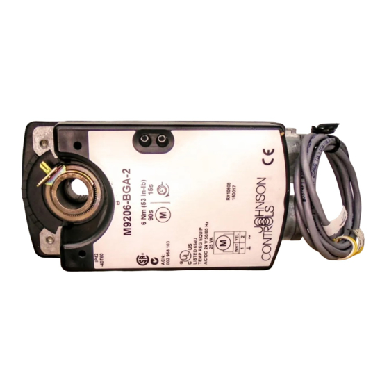
Figure 1: CCW Face of the Actuator
Spring Return Direction - CW Operation
To change the spring return direction to CW, mount
the actuator to the damper shaft so the CW face of the
actuator (Figure 2) is away from the damper. The
actuator now drives CCW from the 0° position.
Arrow
Indicating
CW
Spring Return
Direction
Figure 2: CW Face of the Actuator
The coupler can be inserted in the CW face of the
actuator for easier access to the coupler set screw.
(Refer to the Removable Coupler section.)
Issue Date November 8, 2002
Arrow
Indicating
CCW
Spring Return
Direction
0° Position
Auxiliary
Switch
Adjuster
Located
on the Right
www.johnsoncontrols.com
1
Publicidad
Tabla de contenido

Manuales relacionados para Johnson Controls M9206-B-1S Serie


Resumen de contenidos para Johnson Controls M9206-B-1S Serie
- Página 1 Figure 2: CW Face of the Actuator The coupler can be inserted in the CW face of the actuator for easier access to the coupler set screw. (Refer to the Removable Coupler section.) © 2002 Johnson Controls, Inc. Part No. 34-1280-149, Rev. B www.johnsoncontrols.com...
- Página 2 Removable Coupler Mounting If the damper shaft is less than 81.3 mm (3.2 in.) long, The M9206-Bxx-1S actuators can be mounted in any the coupler must be inserted in the face of the actuator convenient orientation. The actuators can be installed closest to the damper.
- Página 3 Figure 5). screw aligns with the nodule guide that corresponds to the value determined in Step 2. Note: When installing the actuator to a Johnson Controls® D-1300 damper, use the existing Examples: holes in the damper frame. • For a rotation range of 60°, move the coupler so 6.
-
Página 4: Repairs And Replacement
Auxiliary Switch (BxB Models) Wiring The M9206-BxB models have a built-in auxiliary switch with a switch adjuster accessible on either face of the actuator. (See Figure 1 and Figure 2.) The factory WARNING: Risk of Electrical Shock. setting is 20°, nominal. Refer to Auxiliary Switch Disconnect all power supplies before wiring Rating in the Technical Specifications section. -
Página 5: Technical Specifications
The performance specifications are nominal and conform to acceptable industry standards. For application at conditions beyond these specifications, consult the local Johnson Controls office. Johnson Controls, Inc. shall not be liable for damages resulting from misapplication or misuse of its products. -
Página 6: Aufbau Und Einstellungen
Einbauanleitung M9206-Bxx-1S Ausgabe 0902 M 9206-B xx-1S E lektrischer K lappenantrieb m it Federrücklauf • 2-P unkt Montage 0° Stellung ACHTUNG: Bitte diese Instruktion vor dem Anschließen des Gerätes sorgfältig durchlesen. Richtungspfeil für Federrücklauf Hilfsschalter Sicherheitshinweis: Die elektrischen Anschlüsse des gegen den Einstellung, links Uhrzeigersinn... - Página 7 M9206-Bxx-1S Der Adapter kann auf der Seite B des Antriebs gesetzt werden um einen leichteren Zugang zur Adapter- Feststellschraube zu ermöglichen (S. Abschnitt Wechseln des Adapters). Wechseln des Adapters Montage Ist die Klappenachse kürzer als 81.3 mm, so muss der Die M9206-Bxx-1S Antriebe können in jeder beliebigen Adapter auf die Seite des Antriebs gesetzt werden welche Lage montiert werden.
-
Página 8: Drehwinkel Bereich
8 M9206-Bxx-1S 6. Stellen sie sicher das die Klappeflügel zu sehen sind oder das die Klappenposition, am Ende der Klappenachse dauerhaft markiert ist. (Siehe Bild 15.) Bild 15: Klappenposition Markierung 7. Erforderlichen Drehwinkelbereich feststellen und dann diesen Winkel von 90° abziehen. 8. -
Página 9: Elektroanschlüsse
M9206-Bxx-1S Hilfsschalter (BxB Modelle) Elektro-Anschlüsse M9206-BxB Antriebe beinhalten einen eingebauten Hilfsschalter. Die Schaltereinstellung ist von beiden Seiten des Antriebes möglich. (s. Bild 10 und 12) WARNUNG: Elektrischer Schlag. Hinweis: Die Werkseinstellung ist bei 20°<. Bevor Sie mit den Verdrahtungs- oder Instandhaltungsarbeiten beginnen muss die Strom- Der Schaltpunkt ist einstellbar von 0°... -
Página 10: Technische Daten
ACN: 002 968 103 Die oben angegebenen Leistungsspezifikationen sind Nennwerte unter Standardbedingungen. Für Anwendungen außerhalb dieser Bedingungen sprechen Sie mit Ihrem örtlichen JC Büro. Johnson Controls Inc. ist nicht haftbar für Schäden die aus falscher Anwendung durch dieses Produkt entstehen. -
Página 11: Instalación
Instruciónes de Instalación M9206-Bxx-1S Fecha de Publicación 8 de Febrero, 2003 Actuador Eléctrico Activado/Desactivado Serie M9206-Bxx-1S con Regreso por Resorte Instalación IMPORTANTE: El actuador serie Posición de M9206-Bxx-1S esta diseñado para operar bajo 0 grados condiciones normales de trabajo. En aplicaciónes Flecha indicadora donde el mal funcionamiento del M9206-Bxx-1S Ajuste del contacto... -
Página 12: Montaje
Acople Removible Montaje Si el eje del deflector mide menos de 81.3 mm (3.2 Los actuadores M9206-Bxx-1S pueden ser instalados plg.) de largo, el acople debe ser colocado en el lado en cualquier orientación. Se pueden montar en ejes más cercano al deflector. de varios tamaños, incluyendo ejes de 10 a 16 mm (3/8 a 5/8 plg.) de diámetro, o ejes cuadrados de 10 a Cuando el eje del deflector sea menor de 43.2 mm... - Página 13 Figura 21.) Nota: Si está instalando un deflector D-1300 de 4. Reposicione manualmente el acople de tal Johnson Controls, utilice los agujeros existentes en el manera que el tornillo y la ranura del acople estén deflector. alineados con la guía de referencia que 6.
-
Página 14: Conexiones Eléctricas
Control "Activado/Desactivado" • Para restringir el movimiento a 45°, ajuste el de los modelos BDx acople de tal manera que el tornillo y la ranura del acople se encuentren entre las guías de referencia de 40° y 50°. (90° – 45° = 45°) Nota: El ángulo mínimo de rotación es 34.5°. -
Página 15: Reparaciones Y Reemplazos
3. Suministre energía eléctrica al actuador y verifique el funcionamiento del contacto auxiliar. Observe el punto de activación del contacto auxiliar. 4. Si es necesario, ajuste el contacto auxiliar hasta que corresponda al punto requerido. Reparaciones y Reemplazos No intente hacer reparaciones al actuador. Para 4050 reemplazo o accesorios, refiérase al Boletín del Ajuste del... -
Página 16: Las Especificaciones Técnicas
Las Especificaciones Técnicas de funcionamiento de este producto son nominales y están de acuerdo con los estándares de la industria. En aplicaciones donde el producto esté sujeto a condiciones más severas, consulte con la oficina de Johnson Controls, Inc. más cercana.