Publicidad
Idiomas disponibles
Idiomas disponibles
Enlaces rápidos
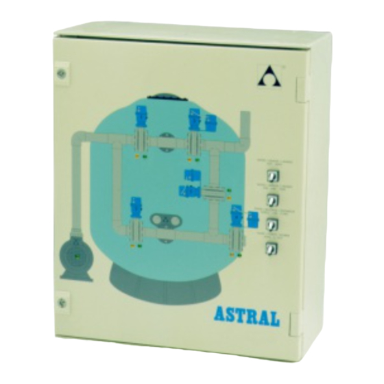
ARMARIO DE MANIOBRAS (Códigos 41005 a 41012)
Les felicitamos por la adquisición del armario de maniobras para el sistema automático de
limpieza de filtros.
Su decisión les honra como comprador, pues ustedes saben que la calidad y la técnica son
fruto de largos años de experiencia.
Sigan estrictamente las instrucciones del manual de uso e instalación, ya que les
suministrará toda la información necesaria sobre el manejo, instalación y mantenimiento que
ustedes tienen que realizar.
1.- COMPROBACIÓN DEL EMBALAJE.
En el interior de la caja encontrará los siguientes accesorios.
• Armario maniobras.
• Presostato.
• Manual de instrucciones.
2.- CARACTERÍSTICAS GENERALES.
LA TENSIÓN DE ALIMENTACIÓN DEL ARMARIO ES DE 220-240 VOLTIOS 50-60 HZ.
LA INTENSIDAD MÁXIMA ADMISIBLE QUE PUEDE SER UTILIZADA EN TODOS LOS
RELÉS, NO SOBREPASARÁ EN NINGÚN MOMENTO LOS 220 VOLTIO/AMPERIO Y
UNA FRECUENCIA DE MANIOBRAS DE 100.000 AL DÍA.
EN EL CASO DE QUE SEA NECESARIO UTILIZAR POTENCIAS O FRECUENCIAS
SUPERIORES,
REALIZAR ESTE TIPO DE TRABAJO.
MANUAL DE INSTALACIÓN Y
INSTALAR
ELEMENTOS
OPERACIÓN
INTERMEDIOS
Rev.:
03
Año:
2011
Pág.:
1 / 17
ESP
PREPARADOS
PARA
Publicidad

Manuales relacionados para Astralpool 41005


Resumen de contenidos para Astralpool 41005
- Página 1 OPERACIÓN Pág.: 1 / 17 ARMARIO DE MANIOBRAS (Códigos 41005 a 41012) Les felicitamos por la adquisición del armario de maniobras para el sistema automático de limpieza de filtros. Su decisión les honra como comprador, pues ustedes saben que la calidad y la técnica son fruto de largos años de experiencia.
- Página 2 Rev.: MANUAL DE INSTALACIÓN Y Año: 2011 OPERACIÓN Pág.: 2 / 17 3.- DESCRIPCIÓN DEL EQUIPO. Armario maniobras para batería de válvulas motorizada con actuadores eléctricos o neumáticos, para realizar automáticamente la función de filtrado, lavado, enjuague y cerrado de los filtros con batería de 4 o 5 válvulas. Equipado con autómata programable que permite realizar todas las funciones requeridas.
- Página 3 Rev.: MANUAL DE INSTALACIÓN Y Año: 2011 Pág.: 3 / 17 OPERACIÓN 4.- SECUENCIA DEL AUTOMATISMO La batería de válvulas estará en posición de cerrado siempre que la/s bomba/s de la filtración estén paradas a consecuencia de que el selector 4 esté en posición ‘0’ o que el reloj programador no de señal de arranque.
- Página 4 Rev.: MANUAL DE INSTALACIÓN Y Año: 2011 OPERACIÓN Pág.: 4 / 17 Cuando todas las válvulas estén correctamente el autómata arranca la/s bomba/s de la filtración para realizar el lavado con el tiempo prefijado por el selector nº 2. Una vez transcurrido el mencionado tiempo, SOLO EN LAS BATERÍAS DE 5 VÁLVULAS pasará...
- Página 5 Rev.: MANUAL DE INSTALACIÓN Y Año: 2011 OPERACIÓN Pág.: 5 / 17 TABLA DE POSICIONAMIENTO DE LAS VÁLVULAS. • BATERÍA 5 VÁLVULAS. POSICIÓN VÁLVULA 1 VÁLVULA 2 VÁLVULA 3 VÁLVULA 4 VÁLVULA 5 FILTRADO ABIERTA CERRADA CERRADA ABIERTA CERRADA LAVADO CERRADA ABIERTA ABIERTA...
- Página 6 Rev.: MANUAL DE INSTALACIÓN Y Año: 2011 OPERACIÓN Pág.: 6 / 17 5.- INSTALACIÓN GENERALIDADES La INSTALACIÓN del ARMARIO debe ser realizada por personal cualificado para este tipo de trabajo. Los instaladores deben de ceñirse estrictamente a las normativas vigentes del país, comunidad o lugar en que se va a instalar el aparato.
- Página 7 Rev.: MANUAL DE INSTALACIÓN Y Año: 2011 OPERACIÓN Pág.: 7 / 17 6.- CONEXIÓN ELÉCTRICA. 6.1.- ALIMENTACIÓN ELÉCTRICA. La tensión de alimentación del armario es de 220-240 Voltios 50-60 Hz. Es imprescindible conectar el cable de puesta a tierra. Fig .7.- Alimentación eléctrica...
- Página 8 Rev.: MANUAL DE INSTALACIÓN Y Año: 2011 OPERACIÓN Pág.: 8 / 17 6.2.- PRESOSTATO. Conectar el borne nº 1 y 4 del presostato con las regletas ‘P-P’ del armario maniobra. El presostato se instalará, en una primera opción, en la te de entrada superior del filtro. Fig .8.- Conexión del presostato...
- Página 9 Rev.: MANUAL DE INSTALACIÓN Y Año: 2011 OPERACIÓN Pág.: 9 / 17 6.3.- BOMBA/S FILTRACIÓN. Los bornes ‘B-B’ suministran tensión 230Vac 50 Hz para la/s bomba/s de filtración en los estados de filtración, lavado y enjuague. Conectar ‘B-B’ con los bornes ‘A1’ y ‘A2’ del contactor/es de la/s bomba/s de filtración Fig .9.- Conexión del contactor/es de filtración...
- Página 10 Rev.: MANUAL DE INSTALACIÓN Y Año: 2011 OPERACIÓN Pág.: 10 / 17 6.4.- BOMBA/S DOSIFICADORA/S. Los bornes ‘D-D’ suministran tensión 230Vac 50 Hz para la/s bomba/s dosificadora/s en el estado de filtración. Bombas de floculante: Conectar ‘D-D’ con los bornes ‘A1’ y ‘A2’ del contactor/es de la/s dosificadora/s.
- Página 11 Rev.: MANUAL DE INSTALACIÓN Y Año: 2011 OPERACIÓN Pág.: 11 / 17 6.5.- CONEXIÓN VÁLVULAS MOTORIZADAS ELÉCTRICAS. Cada válvula motorizada se conectara al grupo correspondiente de 7+1 bornes. Los bornes 1, 2, 3 y tierra, se conectarán al actuador eléctrico. Los bornes 4,6 y 7 se conectarán a los finales de carrera.
- Página 12 Rev.: MANUAL DE INSTALACIÓN Y Año: 2011 OPERACIÓN Pág.: 12 / 17 6.6.- CONEXIÓN VÁLVULAS MOTORIZADAS NEUMÁTICAS. Cada válvula motorizada se conectara al grupo correspondiente de 7+1 bornes. Los bornes 1, 3 y tierra, se conectarán a la electroválvula del actuador. Los bornes 4,6 y 7 se conectarán a los finales de carrera.
- Página 13 Rev.: MANUAL DE INSTALACIÓN Y Año: 2011 OPERACIÓN Pág.: 13 / 17 6.7-ESQUEMAS ELÉCTRICOS.
- Página 14 Rev.: MANUAL DE INSTALACIÓN Y Año: 2011 OPERACIÓN Pág.: 14 / 17...
- Página 15 Rev.: MANUAL DE INSTALACIÓN Y Año: 2011 OPERACIÓN Pág.: 15 / 17 7.- PUESTA EN MARCHA. 1. Seleccionar en el selector nº 2 el tiempo de lavado deseado (normalmente 3 minutos en tratamientos de aguas de piscinas y 6 minutos en potabilizadoras). 2.
- Página 16 Rev.: MANUAL DE INSTALACIÓN Y Año: 2011 OPERACIÓN Pág.: 16 / 17 Que hacer si... • El ARMARIO no arranca la/s bomba/s de la filtración: Verificar que el armario le llega la tensión adecuada. • Verificar que el térmico de la/s bomba/s esté correctamente posicionado. •...
- Página 17 Rev.: MANUAL DE INSTALACIÓN Y Año: 2011 OPERACIÓN Pág.: 17 / 17 ATENCIÓN LEER ATENTAMENTE LAS INSTRUCCIONES DE USO E INSTALACIÓN. • EL ARMARIO Y LA BATERÍA DE VÁLVULAS MOTORIZADAS DEBERÁ INSTALARSE • SIGUIENDO ESTRICTAMENTE EL MANUAL DE INSTRUCCIONES, DEBIENDO OBLIGATORIAMENTE PROCEDERSE VERIFICACIÓN...
-
Página 18: General Features
OPERATION MANUAL Page: 1 / 17 CONTROL BOX PANEL (Codes from 41005 to 41012) Congratulations, you have chosen the most appropriate control panel for the automatic filter backwash system. This article is the result of many years of research in the technical field for the achievement of the highest quality. - Página 19 Rev: INSTALLATION AND Year: 2011 OPERATION MANUAL Page: 2 / 17 3.- EQUIPMENT DESCRIPTION. Control panel for motorized valve batteries with electric or pneumatic actuators to automatically perform the filtering function, washing, rinsing and closing of the filters with manifold of either 4 or 5 valves. Equipped with PLC that allows all the required functions.
- Página 20 Rev: INSTALLATION AND Year: 2011 Page: 3 / 17 OPERATION MANUAL 4.- PROCESS DESCRIPTION The valve manifold will stay in the “close” position as long as the filtration pump/s stays still as a result of selector 4 showing 0. Another reason may be the time clock giving no starting signal. As soon as the PLC starts off the filtration pump/s, the valves of the manifold will turn to the “filtration”...
- Página 21 Rev: INSTALLATION AND Year: 2011 OPERATION MANUAL Page: 4 / 17 When the position of all the valves is correct the plc starts off the filtration pump/s for the beginning of “backwash” according to the time chosen for switch nº 2. Once the mentioned time is over, ONLY 5-VALVE MANIFOLD turn to the “rinse”...
- Página 22 Rev: INSTALLATION AND Year: 2011 OPERATION MANUAL Page: 5 / 17 VALVES POSITION TABLE. • 5 VALVE MANIFOLD. POSITION VALVE 1 VALVE 2 VALVE 3 VALVE 4 VALVE 5 FILTRATION OPEN CLOSED CLOSED OPEN CLOSED BACKWASH CLOSED OPEN OPEN CLOSED CLOSED RINSE OPEN...
-
Página 23: General Information
Rev: INSTALLATION AND Year: 2011 OPERATION MANUAL Page: 6 / 17 5.- INSTALLATION GENERAL INFORMATION The installation of the CONTROL BOX has to be made by qualified technicians. The installers must follow strictly the standards in force in the country, community or place where the control box will work. - Página 24 Rev: INSTALLATION AND Year: 2011 OPERATION MANUAL Page: 7 / 17 6.- ELECTRICAL CONNECTION. 6.1.- POWER SUPPLY. The control box power supply is 220-240 Volts 50-60 Hz is essential to connect the grounding cable. Fig. 7.- Power supply connection...
- Página 25 Rev: INSTALLATION AND Year: 2011 OPERATION MANUAL Page: 8 / 17 6.2.- PRESSURE CONTROLLER. Connect terms nº 1 and 4 of the pressure controller to the control box ‘P-P’ lead. The pressure controller shall be installed, as a first option, in the inlet tee located on the upper part of the filter.
- Página 26 Rev: INSTALLATION AND Year: 2011 OPERATION MANUAL Page: 9 / 17 6.3.- FILTRATION PUMP/S. The 'BB' terminals supply voltage 230VAC 50 Hz for the filter pump/s in the states of filtration, washing and rinse. Connect 'BB' to the terminals 'A1' and 'A2' from the contactor/s of the pump/s Fig .9.- Filtration pump/s connection...
- Página 27 Rev: INSTALLATION AND Year: 2011 OPERATION MANUAL Page: 10 / 17 6.4.- DOSING PUMP/S. The 'DD' terminals supply voltage 230VAC 50 Hz for the dosing pump/s in the ‘filtration’ state. Flocculant dosing pump/s: Connect the ‘D-D’ leads terms to the A1 and A2 from the contactor/s of the flocculant dosing pump/s.
- Página 28 Rev: INSTALLATION AND Year: 2011 OPERATION MANUAL Page: 11 / 17 6.5.- ELECTRICAL MOTORIZED VALVES CONNECTION. Connect the lead’s terms to the valve connector according to the picture. Repeat the same process with the other valves, having connected them previously in strict order (connector nº...
- Página 29 Rev: INSTALLATION AND Year: 2011 OPERATION MANUAL Page: 12 / 17 6.6.- PNEUMATIC MOTORIZED VALVES CONNECTION. Connect the lead’s terms to the valve connector according to the picture. The nº2 Lead is not used. Make a bridge with lead nº5 (common) and nº 1 on the limit switch Repeat the same process with the other valves, having connected them previously in strict order (connector nº...
- Página 30 Rev: INSTALLATION AND Year: 2011 OPERATION MANUAL Page: 13 / 17 6.7-ELECTRICAL DIAGRAM. ELECTRIC BOX DIAGRAM 5 VALVES MANIFOLD AUTOMATIC POWER...
- Página 31 Rev: INSTALLATION AND Year: 2011 OPERATION MANUAL Page: 14 / 17 ELECTRIC BOX DIAGRAM 4 VALVES MANIFOLD AUTOMATIC POWER...
- Página 32 Rev: INSTALLATION AND Year: 2011 OPERATION MANUAL Page: 15 / 17 7.- STARTING-OFF. 1. Select the time for backwash with help of switch nº 2 (normally 3 minutes for swimming pool water treatment and 6 minutes for drinking water installations). 2.
- Página 33 Rev: INSTALLATION AND Year: 2011 OPERATION MANUAL Page: 16 / 17 What if... • The CONTROL BOX does not start off the filtration pump/s: Check the appropriate tension of the control box. • Check the correct position of the pump/s’ motor protector. •...
- Página 34 Rev: INSTALLATION AND Year: 2011 OPERATION MANUAL Page: 17 / 17 IMPORTANT: READ CAREFULLY THE INSTRUCTIONS FOR INSTALLATION AND USE. • THE CONTROL BOX AND THE MOTORIZED VALVES MANIFOLD MUST BE • INSTALLED CARRYING THE INSTRUCTIONS IN THE HANDBOOK TO THE LETTER. IT IS ESSENTIAL THAT THE CORRECT WORKING OF THE CONTROL BOX SHOULD BE VERIFIED BEFORE STARTING IT OFF.