Tabla de contenido
Publicidad
Idiomas disponibles
Idiomas disponibles
Enlaces rápidos
Leggere attentamente le istruzioni prima di installare e utilizzare l'apparecchiatura.
Read the instructions carefully before installing and using the appliance.
Vor der Installation und Nutzung des Geräts müssen die Anleitungen aufmerksam durchgelesen werden.
Lire attentivement les instructions avant d'installer et d'utiliser l'appareil.
Léanse atentamente las instrucciones antes de instalar y utilizar el aparato.
Il mancato rispetto delle istruzioni fa decadere la garanzia del fabbricante.
In the event of failure to comply with the instructions, the manufacturer's warranty shall cease to apply.
Die Missachtung der Anleitungen hat den Verfall der vom Hersteller gewährten Garantie zur Folge.
Le non respect des instructions entraîne l'invalidation de la garantie du fabricant.
La inobservancia de las instrucciones provoca la invalidación de la garantía otorgada por el fabricante.
CUCINA FUOCHI APERTI+FORNO
OPEN BURNER RANGE+ OVEN
GASHERD MIT OFFENEN FLAMMEN+ BACKOFEN
CUISINIÈRE FEUX VIFS+ FOUR
COCINA FUEGOS ABIERTOS+ HORNO
ISTRUZIONI PER L'UTILIZZATORE
1N1FAGV - 1T1FAAGV
1N1FADGV - 1T1FADGV
1N1TNGV - 1T1TNGV
2N1FAGV - 2T1FAGV
2N1FAAGV - 2T1FAAGV
3N1FAGV - 3T1FAGV
USE MANUAL
BEDIENSHANDBUCH
MANUEL D'UTILISATION
MANUAL DE USO
Italiano
GB
English
Deutsch
FR
Français
Español
Rev.2 07/2017
3319990
IT
DE
ES
Publicidad
Capítulos
Tabla de contenido
Solución de problemas

Manuales relacionados para Angelo Po 1N1FAGV


Resumen de contenidos para Angelo Po 1N1FAGV
- Página 1 Le non respect des instructions entraîne l’invalidation de la garantie du fabricant. La inobservancia de las instrucciones provoca la invalidación de la garantía otorgada por el fabricante. CUCINA FUOCHI APERTI+FORNO 1N1FAGV - 1T1FAAGV OPEN BURNER RANGE+ OVEN 1N1FADGV - 1T1FADGV...
- Página 2 Cautela - Avvertenza Importante Important Wichitig Important Importante Verifi care quotidianamente che i dispositivi Non usare prodotti che contengono sostanze di sicurezza siano perfettamente installati ed dannose e pericolose per la salute delle per- effi cienti. sone (solventi, benzine, ecc.). Cautela - Avvertenza Cautela - Avvertenza La pavimentazione, in prossimità...
-
Página 3: Tabla De Contenido
SOMMARIO INFORMAZIONI GENERALI ........2 ISTRUZIONI E AVVERTENZE PER IL LETTORE ........2 SCOPO DEL MANUALE . -
Página 4: Informazioni Generali
INFORMAZIONI GENERALI ISTRUZIONI E AVVERTENZE PER IL LETTORE Per rintracciare facilmente gli argomenti spe- Questo manuale contiene tutte le informazioni cifi ci di interesse, consultare l’indice analitico necessarie ai destinatari eterogenei, cioè gli uti- postoall’inizio del manuale. lizzatori dell’apparecchiatura. SCOPO DEL MANUALE Questo manuale, che è... -
Página 5: Identificazione Fabbricante E Apparecchiatura
MODALITÀ DI RICHIESTA ASSISTENZA Per qualsiasi esigenza rivolgersi alle agenzie Per ogni richiesta di assistenza tecnica, indicare o alla sede centrale Angelo Po i cui riferimenti i dati riportati sulla targhetta di identifi cazione sono riportati nella sezione contatti del sito ed il tipo di difetto riscontrato. -
Página 6: Informazioni Tecniche
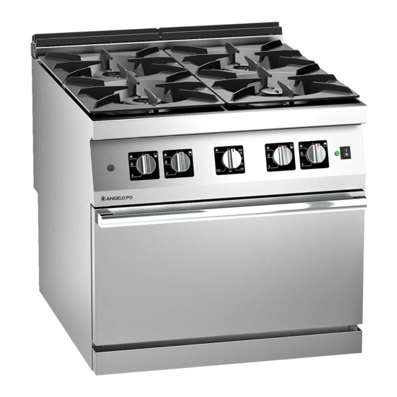
INFORMAZIONI TECNICHE DESCRIZIONE GENERALE APPARECCHIATURA La cucina fuochi aperti con forno, d’ora innanzi In funzione delle esigenze di utilizzo, l’apparec- defi nita apparecchiatura, è stata progettata chiatura è prodotta in più versioni (vedi fi gura). e costruita per la preparazione e cottura di alimenti nell’ambito della ristorazione profes- sionale. -
Página 7: Dispositivi Di Sicurezza
Organi principali Piano di cottura: realizzato in acciaio inox. Bruciatori di piano: realizzati in ghisa smaltata, possono fornire potenze variabili in funzione della loro dimensione Scarico fumi: per evacuare i fumi del forno. Pulsante accensione: per accendere il brucia- tore del forno Manopola comando forno: serve per regola- re l’alimentazione gas del bruciatore del forno Manopole comando bruciatori di piano:... -
Página 8: Segnali Di Sicurezza E Informazione
SEGNALI DI SICUREZZA E INFORMAZIONE L’illustrazione indica la posizione dei segnali applicati. Targa identifi cazione fabbricante e apparecchiatura. Pericolo generico: prima di eff ettuare qualsi- asi tipo di intervento, leggere attentamente il manuale. Pericolo generico: durante il lavaggio dell’ap- parecchiatura non dirigere getti d’acqua in pressione sulle parti interne. -
Página 9: Sicurezza
SICUREZZA ISTRUZIONI E AVVERTENZE PER LA SICUREZZA Il fabbricante, in fase di progettazione e co- essere eseguiti esclusivamente da personale de- struzione, ha posto particolare attenzione agli bitamente qualifi cato, e/o abilitato e comunque aspetti che possono provocare rischi alla sicu- con esperienza riconosciuta e acquisita nel setto- rezza e alla salute delle persone che interagisco- re specifi co di intervento. -
Página 10: Istruzioni E Avvertenze Per La Sicurezza Sull'impatto Ambientale
Cautela - Avvertenza Cautela - Avvertenza Non ostruire il camino per evitare l’aumento La pavimentazione, in prossimità dell’appa- eccessivo della temperatura dei componenti recchiatura potrebbe essere scivolosa. e prodotti di combustione superiori ai limiti ammessi. Importante Important Wichitig Important Importante I collegamenti necessari (acqua, elettricità... -
Página 11: Uso E Funzionamento
USO E FUNZIONAMENTO ISTRUZIONI E AVVERTENZE PER L’USO E IL FUNZIONAMENTO Importante Important Wichitig Important Importante Gli utilizzatori, oltre ad essere autorizzati ed Prima dell’uso verifi care che i dispositivi di opportunamente documentati, formati ed sicurezza siano perfettamente installati ed addestrati, se necessario, al primo uso, do- effi cienti. -
Página 12: Accensione E Spegnimento Bruciatori Di Piano
ACCENSIONE E SPEGNIMENTO BRUCIATORI DI PIANO Accensione Aprire il rubinetto alimentazione gas. Premere e ruotare la manopola in senso antiorario (pos. ) ed accendere la spia pilota. Mantenere premuta la manopola per circa 15 sec. per consentire l’intervento della termo- coppia. -
Página 13: Ripristino Apparecchiatura
Spegnimento Premere e ruotare la manopola in senso orario Ruotare la manopola in senso orario (pos. (pos. 4) per spegnere la spia pilota. 3) per spegnere il bruciatore. La spia pilota Chiudere il rubinetto per garantire condizioni rimarrà accesa per successive riaccensioni del di sicurezza. -
Página 14: Manutenzione
MANUTENZIONE ISTRUZIONI ED AVVERTENZE PER LA MANUTENZIONE Assicurarsi, inoltre, che, durante l’interven- Mantenere l’apparecchiatura in condizioni di to di manutenzione, l’operatore sia sempre massima effi cienza, grazie alle operazioni di ma- in grado di poter controllare che la spina sia nutenzione programmata previste dal fabbrican- disinserita dalla presa di corrente. -
Página 15: Pulizia Piano Di Cottura, Bruciatori E Accessori
– Utilizzare getti d’acqua in pressione solo sulle – Pulire tempestivamente i residui di cibo per parti esterne. evitare che induriscano. – Prestare attenzione alle superfi ci in acciaio inox – Pulire i depositi calcarei che possono formarsi per non danneggiarle. In particolare, evitare in alcune superfi ci dell’apparecchiatura. -
Página 16: Pulizia Forno
Per qualsiasi esigenza rivolgersi alle agenzie aiutare l’identifi cazione e correzione di eventuali o alla sede centrale Angelo Po i cui riferimen- anomalie e disfunzioni che potrebbero presen- ti sono riportati nella sezione contatti del sito tarsi in fase d’uso. - Página 17 Inconvenienti Cause Rimedi La fi amma è gialla. Bruciatore sporco. Pulire il bruciatore Diffi coltà nella rotazione Importante Malfunzionamento del della manopola comando rubinetto valvolato gas. bruciatore. Contattare il servizio assistenza. Ripristinare il termostato di Intervento del termostato di sicurezza (vedi pag. 11), se il pro- sicurezza del forno.
- Página 18 Caution - Warning Important Make a daily check that the safety devices Never use products containing substances are properly installed and in good working harmful or hazardous for health (solvents, order. petroleum spirits, etc.). Caution - Warning Caution - Warning The fl oor, near the appliance, could be slip- Before doing any work, cut off the mains pery.
- Página 19 SUMMARY GENERAL INFORMATION ........2 INSTRUCTIONS AND WARNINGS FOR THE READER .
-
Página 20: General Information
GENERAL INFORMATION INSTRUCTIONS AND WARNINGS FOR THE READER To fi nd the specifi c topics of interest to you This manual contains all of the required infor- quickly, refer to the index at the start of the mation for diff erent types of recipients, i.e. users manual. -
Página 21: Identification Of Manufacturer And Appliance
PROCEDURE FOR REQUESTING SERVICE For all requirements contact the agents or the When requesting service, state the data provi- headquarters of Angelo Po which can be found de on the nameplate and provide a description in the contacts section of the website http:// of the fault. -
Página 22: Technical Information
TECHNICAL INFORMATION GENERAL DESCRIPTION OF APPLIANCE The open burner range with oven, referred to The appliance is produced in several versions from now on as the appliance, is designed and to meet varying user requirements (see dia- constructed for preparing and cooking foods in gram). -
Página 23: Safety Devices
Main Parts Hob: in stainless steel. Top burners: in enamelled cast iron, the po- wer they are able to supply varies depending on their size. Fume exhaust vent: for removal of the fumes from the oven. Ignition button: for lighting the oven burner Oven control knob: regulates the gas supply to the oven burner Top burner control knobs: regulate the gas... -
Página 24: Safety And Information Signs
SAFETY AND INFORMATION SIGNS The illustration shows the position of the signs provided. Nameplate with manufacturer and appliance data. General hazard:read the manual carefully before carrying out any procedure. General hazard: when washing the appliance do not point pressurised water jets at internal parts. -
Página 25: Safety
SAFETY INSTRUCTIONS AND WARNINGS FOR SAFETY During design and construction, the manufac- To maintain hygiene and protect the food turer has paid special attention to factors which processed from all forms of contamination, may cause risks to the health and safety of the all elements in direct or indirect contact with people interacting with the appliance. -
Página 26: Safety Warnings And Instructions Concerning Environmental
Caution - Warning Do not obstruct the fl ue to avoid the tempe- rature of the combustion components and products from increasing excessively over the admissible limits. SAFETY WARNINGS AND INSTRUCTIONS CONCERNING ENVIRONMENTAL IMPACT Every organisation is obliged to apply proce- –... -
Página 27: Use And Operation
USE AND OPERATION INSTRUCTIONS AND WARNINGS FOR USE AND OPERATION Important Besides being authorised and appropriately Before use, check that the safety devices are documented,and if necessary,instructed and properly installed and in good working or- trained, users,on fi rst usage, have to simula- der. -
Página 28: Switching The Top Burner On And Off
SWITCHING THE TOP BURNER ON AND OFF Lighting Turn on the gas supply tap. Press the knob and turn it anti-clockwise (pos. ) to light the pilot light. Keep the knob pressed for about 15 sec. to prime the thermocouple. Turn the knob (A) anti-clockwise (pos. -
Página 29: Turning Off
Turning off Press the knob (A) and turn it clockwise (pos. Turn the knob clockwise (pos. 3) to turn the 4) to turn off the pilot light. burner off . The pilot light will remain on to Turn off the gas supply tap to ensure safety. allow the burner to be re-lit. -
Página 30: Servicing
SERVICING INSTRUCTIONS AND WARNINGS FOR SERVICING Keep the appliance at peak effi ciency by car- At the end of each session of use and whenever rying out the scheduled servicing procedures necessary, clean: recommended by the manufacturer. Proper ser- – The hob (see page 13) vicing will allow the best performance, a longer –... -
Página 31: Cleaning The Hob, Burners And Accessories
– Rinse surfaces with drinking water and dry. – Remove food residues immediately before they set. – Pressurised water jets may only be used on external parts. – Remove the limescale deposits which may form on some of the appliance’s surfaces. –... -
Página 32: Cleaning Oven
For all requirements contact the agents or correction of any anomalies and malfunctions the headquarters of Angelo Po which can be which might occur during use. found in the contacts section of the website http://www.angelopo.com. - Página 33 Faults Causes Remedies The fl ame is yellow. Burner dirty. Clean the burner Gas control valve malfun- Important Burner control knob is stiff . ction Contact the after-sales service. Reset the safety thermostat (see Safety thermostat tripped page 11); if the problem persists, (Oven) call the after-sales service.
- Página 34 Vorsicht - Achtung Wichitig Stellen Sie jeden Tag durch Kontrollen sicher, Verwenden Sie keine Produkte, die Stoff e en- dass die Sicherheitsvorrichtungen fachgerecht thalten, welche für die menschliche Gesun- installiert sind und einwandfrei funktionieren. dheit schädlich und gefährlich sind (Lösemit- tel, Benzin, usw.).
- Página 35 INHALTSVERZEICHNIS ALLGEMEINES ..........2 ANWEISUNGEN UND WARNHINWEISE FÜR DEN LESER .
-
Página 36: Allgemeines
ALLGEMEINES ANWEISUNGEN UND WARNHINWEISE FÜR DEN LESER Konsultieren Sie das Sachregister, das am An- Dieses Handbuch enthält alle notwendigen In- fang des Handbuchs zu fi nden ist, um leichter formationen für unterschiedliche Benutzer, d.h. unter bestimmten Themen von besonderem für alle Nutzer des Geräts. Interesse nachschlagen zu können. -
Página 37: Typenschild Für Hersteller Und Gerät
Geben Sie bei jedem Kontakt mit dem Kunden- Handelsvertretungen oder den Hauptsitz des dienstzentrum nicht nur den aufgetretenen Unternehmens Angelo Po, die entsprechenden Schaden, sondern auch die Daten an, die auf Kontaktdaten sind auf der Webseite http://www. dem Typenschild angeführt sind. -
Página 38: Technische Informationen
TECHNISCHE INFORMATIONEN ALLGEMEINE BESCHREIBUNG DES GERÄTS Der Gasherd mit off enen Flammen + Backo- Das Gerät wird bedarfsabhängig in verschiede- fen, der im Folgenden als Gerät bezeichnet nen Versionen hergestellt (siehe Abbildung). wird, wurde zum Zubereiten und Garen von Speisen in Restaurantbetrieben projektiert und konstruiert. -
Página 39: Sicherheitsvorrichtungen
Hauptorgane Kochmulde: aus Edelstahl. Kochstellenbrenner: aus emailliertem Gus- seisen, Heizleistung von Größe abhängig Wrasenöff nung: für den Austritt des Dampfes aus dem Backofen. Taste Zündung: Zum Zünden des Backo- fenbrenners. Backofen-Schalter: zum Einstellen der Heizleistung des Backofens Schalter der Kochstellenbrenner: zum Einstellen der Heizleistung der Kochstel- lenbrenner Backofen mit Thermostat: aus Stahl, mit... -
Página 40: Sicherheitshinweise Und Informationen
SICHERHEITSHINWEISE UND INFORMATIONEN Die Abbildung zeigt die Anordnung der aufgeklebten Sicherheitshinweise. Typenschild mit Angabe des Herstellers und der Gerätekenndaten. Allgemeine Gefahr: Vor Ausführung irgen- deines Eingriff s zuerst das Handbuch aufmer- ksam lesen. Allgemeine Gefahr: Beim Waschen des Geräts den Wasserstrahl nicht direkt auf die inneren Teile richten. -
Página 41: Sicherheit
SICHERHEIT ANWEISUNGEN UND WARNHINWEISE FÜR DIE SICHERHEIT Der Hersteller hat bei Entwicklung und Ferti- Alle Wartungseingriff e, die technisches Fach- gung dieses Produkts besondere Sorgfalt auf wissen oder spezielle Fähigkeiten oder eine Aspekte verwendet, die eine Gefahr für die Si- gesetzlich vorgeschriebene Ausbildung erfor- cherheit und die Gesundheit der Personen, die dern, dürfen ausschließlich von entsprechend... -
Página 42: Anweisungen Und Warnhinweise Für Die In Hinblick Auf Die
Keine entzündlichen Gegenstände oder Mate- Vorsicht - Achtung rialien im Schrank oder in der Nähe des Geräts aufbewahren. Den Schornstein nicht verstellen, um einen übermäßigen Temperaturanstieg der Bautei- Vorsicht - Achtung le und der Verbrennungspodukte über die zulässigen Grenzen hinaus zu verhindern. Der Boden in der Nähe des Gerätes könnte rutschig sein. -
Página 43: Gebrauch Und Betrieb
GEBRAUCH UND BETRIEB ANWEISUNGEN UND WARNHINWEISE FÜR DIE BEDIENUNG UND BETRIEB Vor dem Gebrauch sicherstellen, dass die Si- Wichitig cherheitsvorrichtungen ordnungsgemäß in- stalliert und funktionsfähig sind. Die Anwender müssen nicht nur befugt und angemessen informiert, ausgebildet und ge- Die Benutzer müssen diese Vorschriften und schult sein sondern ggf. -
Página 44: Ein- Und Ausschalten Der Kochstellenbrenner
EIN- UND AUSSCHALTEN DER KOCHSTELLENBRENNER Zündung Öff nen Sie den Gashahn. Den Schalter niederdrücken und entgegen dem Uhrzeigersinn drehen (pos. ) und die Zündfl amme zünden. Halten Sie den Bedienknebel etwa 15 Sekun- den lang gedrückt, damit das Thermoelement in Aktion treten kann. Drehen Sie den Bedienknebel (A) im Ge- genuhrzeigersinn (pos. -
Página 45: Rücksetzen Des Geräts
Abschaltung Drehen Sie den Bedienknebel im Uhrzeiger- Drehen Sie den Bedienknebel im Uhrzeigersinn sinn (pos. 4), um den Zündfl ammenbrenner (pos. 3), um den Brenner abzuschalten. Der auszuschalten. Zündfl ammenbrenner bleibt für die folgenden Öff nen Sie den Gashahn. Zündungen des Brenners eingeschaltet. RÜCKSETZEN DES GERÄTS Wenn der Sicherheitsthermostat anspricht, muss das Gerät in der angegebenen Weise wie-... -
Página 46: Wartung
WARTUNG ANWEISUNGEN UND WARNHINWEISE FÜR DIE WARTUNG Außerdem muss garantiert sein, dass wäh- Sorgen Sie dafür, dass das Gerät im Zustand rend der Wartungseingriff e der Bediener im- maximaler Leistungsfähigkeit bleibt, indem Sie mer in der Lage ist, sicherzustellen, dass der die vom Hersteller vorgesehenen planmäßigen Stecker aus der Steckdose gezogen ist. -
Página 47: Reinigung Der Kochmulde, Brenner Und Zubehörteile
– Spülen Sie die Oberfl ächen mit Trinkwasser Scheuermitteln und spitzen Gegenständen nach und trocknen Sie sie ab. vermieden werden. – Nur die äußeren Teile dürfen mit einem Was- – Essensreste müssen so schnell wie möglich serstrahl gereinigt werden. entfernt werden, bevor sie eintrocknen und –... -
Página 48: Reinigung Des Backofens
Ihnen dabei helfen, eventuelle Anomalien oder Handelsvertretungen oder den Hauptsitz Funktionsstörungen, die während des Betriebs des Unternehmens Angelo Po, die entspre- auftreten können, aufzufi nden und zu beheben. chenden Kontaktdaten sind auf der Websei- Einige dieser Probleme können vom Benutzer te http://www.angelopo.com unter „Kontakt“... - Página 49 Probleme Ursachen Lösungen Die Flamme ist gelb. Brenner verschmutzt. Den Brenner reinigen. Wichitig Schwierigkeiten beim Fehlfunktion des vollgesicher- Drehen des Brennerschalters. ten Gasventils Kontaktieren Sie den Kundendienst. Den Sicherheitsthermostaten Auslösung des Sicherheits- zurücksetzen (siehe Seite 11). Wenn thermostats (Backofen) das Problem weiterhin vorliegt, den Kundendienst kontaktieren.
- Página 50 Attention Important Vérifi er quotidiennement que les dispositifs Ne pas utiliser de produits qui contiennent de sécurité soient parfaitement installés et des substances dangereuses pour la santé effi caces. des personnes (solvants, essences, etc.). Attention Attention Le sol, à proximité de l’appareil, pourrait être Avant toute intervention, couper l’alimenta- glissant.
- Página 51 INDEX INFORMATIONS GÉNÉRALES ....... . . 2 INSTRUCTIONS ET AVERTISSEMENTS POUR LE LECTEUR ......2 BUT DU MANUEL .
-
Página 52: Informations Générales
INFORMATIONS GÉNÉRALES INSTRUCTIONS ET AVERTISSEMENTS POUR LE LECTEUR Pour retrouver facilement les sujets qui vous Ce manuel contient toutes les informations intéressent, consulter l’index analytique au nécessaires aux destinataires hétérogènes, c’est- début du manuel. à-dire les utilisateurs de l’appareil. BUT DU MANUEL Ce manuel, qui fait partie intégrante de l’appa- Le fabricant se réserve le droit d’apporter des reil, a été... -
Página 53: Identification Du Fabricant Et De L'appareil
DEMANDE D’ASSISTANCE Pour toute exigence, s’adresser aux agences ou Pour toute demande d’assistance technique, au siège centra Angelo Po dont les références indiquer les données reportées sur la plaque sont reportées dans la section contacts du site d’identifi cation et le type de défaut relevé. -
Página 54: Informations Techniques
INFORMATIONS TECHNIQUES DESCRIPTION GÉNÉRALE DE L’APPAREIL Le fourneau feux vifs sur four, que l’on appelle- En fonction des exigences d’utilisation, l’ap- ra maintenant appareil, a été conçu et fabriqué pareil est réalisé en plusieurs versions (voir pour la préparation et la cuisson d’aliments fi gure). -
Página 55: Dispositifs De Sécurité
Organes principaux Plan de travail : en acier inox. Brûleurs fourneau : en fonte émaillée, ils peuvent fournir des puissances variables en fonction de leur dimension. Evacuation des fumées : pour évacuer les fumées du four. Bouton d’allumage : pour allumer le brûleur du four Manette de commande du four : pour régler l’alimentation du gaz du brûleur du four... -
Página 56: Signaux De Sécurité Et Information
SIGNAUX DE SÉCURITÉ ET INFORMATION L’illustration indique la position des signaux appliqués. Plaque d’identifi cation du fabricant et de l’appareil. Risque générique: avant tout type d’inter- vention, lire attentivement ce manuel. Risque générique: pendant le lavage de l’appareil ne pas diriger de jets d’eau sous pression sur les pièces intérieures. -
Página 57: Sécurité
SÉCURITÉ INSTRUCTIONS ET MISES EN GARDE POUR LA SÉCURITÉ Le fabricant, lors de la conception et de la fa- spécifi que d’intervention. brication, a fait très attention aux aspects qui Pour maintenir l’hygiène et protéger les ali- peuvent provoquer des risques à la sécurité et ments de tous les phénomènes de contami- à... -
Página 58: Instructions Et Mises En Garde De Sécurité Pour L'impact
Attention Important Ne pas obstruer la cheminée pour éviter Les raccordements nécessaires (eau, élec- l’augmentation excessive de la température tricité et gaz) doivent être eff ectués exclu- des composants et produits de combustion sivement par du personnel adéquatement supérieurs aux limites admises. spécialisé, conformément aux dispositions locales. -
Página 59: Utilisation Et Fonctionnement
UTILISATION ET FONCTIONNEMENT INSTRUCTIONS ET AVERTISSEMENTS POUR L’UTILISATION ET FONCTIONNEMENT Important Les utilisateurs, en plus d’être autorisés et Avant l’utilisation, vérifi er si les dispositifs de documentés de façon appropriée, formés et sécurité sont parfaitement installés et effi - entraînés, si nécessaire, lors de la première caces. -
Página 60: Allumage Et Extinction Brûleurs Fourneau
ALLUMAGE ET EXTINCTION BRÛLEURS FOURNEAU Allumage Ouvrir le robinet d’alimentation du gaz. Pousser et tourner la manette en sens anti- horaire (pos. ) pour allumer la veilleuse pilote. Continuer à appuyer sur la manette pendant environ 15 s pour permettre l’intervention du thermocouple. -
Página 61: Rétablissement Des Fonctions De L'appareil
Extinction Presser et tourner la manette en sens horaire Tourner la manette en sens horaire (pos. 3) (pos. 4) pour éteindre la veilleuse pilote. pour éteindre le brûleur. La veilleuse pilote Fermer le robinet pour garantir les conditions restera allumée pour des rallumages successifs de sécurité. -
Página 62: Entretien
ENTRETIEN INSTRUCTIONS ET AVERTISSEMENTS POUR L’ENTRETIEN Maintenir l’appareil en parfait état de fonction- S’assurer, en outre, que, pendant l’interven- nement en eff ectuant les opérations d’entretien tion d’entretien, l’opérateur soit toujours programmé prévues par le fabricant. Un bon en- en mesure de pouvoir contrôler que la fi che tretien permettra d’obtenir les meilleures perfor- soit débranchée de la prise de courant. -
Página 63: Nettoyage De La Table De Cuisson, Des Brûleurs Et Des Accessoires
– De rincer les surfaces avec de l’eau potable et – De nettoyer rapidement les résidus d’aliment les essuyer. pour éviter qu’ils durcissent. – Utiliser des jets d’eau sous pression unique- – De nettoyer les dépôts calcaires qui peuvent ment sur les parties extérieures. se former sur certaines surfaces de l’appareil. -
Página 64: Nettoyage Du Four
à l’identifi cation et à la correction Pour toute exigence, s’adresser aux agences d’éventuels pannes et dysfonctionnements qui ou au siège centra Angelo Po dont les ré- pourraient se présenter en cours d’utilisation. férences sont reportées dans la section Certains de ces problèmes peuvent être résolus... - Página 65 Inconvénients Causes Solutions La fl amme est jaune. Brûleur sale. Nettoyer le brûleur Diffi culté de rotation de la Mauvais fonctionnement du Important manette de commande du robinet gaz de sécurité brûleur. Contacter le service assistance. Réenclencher le thermostat de Intervention du thermostat sécurité...
- Página 66 Precaución - advertencia Importante No usar productos que contengan sustancias Controlar periódicamente que los equipos de nocivas y/o peligrosas para la salud de las seguridad se encuentren en perfecto estado y personas (disolventes, bencinas, etc.). estén correctamente instalados. Precaución - advertencia Precaución - advertencia Antes de realizar cualquier operación se de- El pavimento, cerca del equipo, podría ser re-...
- Página 67 ÍNDICE INFORMACIONES DE CARÁCTER GENERAL ....2 INSTRUCCIONES Y ADVERTENCIAS PARA EL LECTOR ......2 OBJETIVO DEL MANUAL .
-
Página 68: Informaciones De Carácter General
INFORMACIONES DE CARÁCTER GENERAL INSTRUCCIONES Y ADVERTENCIAS PARA EL LECTOR Para ubicar fácilmente los temas específi cos Este manual incluye toda la información necesa- de interés, consúltese el índice analítico que se ria para los destinatarios heterogéneos, es decir, encuentra al inicio del manual. para los usuarios del equipo. -
Página 69: Identificación Fabricante Y Equipo
MODALIDAD PARA REQUERIR ASISTENCIA Para cualquier necesidad, diríjase a las agen- Para solicitar asistencia técnica deberán cias o a la sede central de Angelo Po, cuyos indicarse los datos reproducidos en la placa de referentes se indican en la sección de contac- identifi cación y el tipo de desperfecto que se... -
Página 70: Informaciones De Carácter Técnico
INFORMACIONES DE CARÁCTER TÉCNICO DESCRIPCIÓN GENERAL DEL EQUIPO La cocina fuegos abiertos con horno, que de El aparato es producido en varias versiones en ahora en adelante llamaremos aparato, ha sido función de los requerimientos específi cos de proyectada y fabricada para la preparación y la uso (véase fi gura). -
Página 71: Órganos Principales
Órganos principales Encimera: fabricada en acero inox. Quemadores de plano: realizados en fundi- ción esmaltada, pueden proporcionar poten- cias variables en función de sus dimensiones Salida de humos: para evacuar los humos generados por el horno. Botón de encendido: para encender el que- mador del horno. -
Página 72: Señalizaciones De Seguridad E Información
SEÑALIZACIONES DE SEGURIDAD E INFORMACIÓN La ilustración indica la posición de las señaliza- ciones fi jadas en el equipo. Placa de identifi cación fabricante y aparato. Peligro genérico: antes de efectuar cualquier tipo de intervención leer atentamente el manual. Peligro genérico: durante el lavado del apa- rato no dirigir chorros de agua a presión hacia sus partes internas. -
Página 73: Seguridad
SEGURIDAD INSTRUCCIONES Y ADVERTENCIAS PARA LA SEGURIDAD Durante las fases de diseño y producción el previstas por la Ley tienen que ser realizadas fabricante ha prestado especial atención a los exclusivamente por personal debidamente cua- factores que pueden provocar riesgos en cuanto lifi cado y/o habilitado y de todas formas con a seguridad y salud de las personas que inte- experiencia reconocida y adquirida en el sector... -
Página 74: Instrucciones Y Advertencias De Seguridad Para El Impacto
Precaución - advertencia Precaución - advertencia No obstruya la chimenea para evitar el au- El pavimento, cerca del equipo, podría ser mento excesivo de la temperatura de los resbaladizo. componentes y de los productos de combus- Importante Importante tión superiores a los límites admitidos. Las conexiones necesarias (agua, electricidad y gas) se deben realizar exclusivamente por el personal especializado de manera adecua-... -
Página 75: Uso Y Funcionamiento
USO Y FUNCIONAMIENTO INSTRUCCIONES Y ADVERTENCIAS PARA EL USO Y FUNCIONAMIENTO Importante Los utilizadores, además de estar autorizados Antes del uso, controlar que los dispositivos y oportunamente documentados, formados y de seguridad estén instalados de forma co- adiestrados, si fuera necesario, con el primer uso, rrecta y efi caz. -
Página 76: Encendido Y Apagado Quemadores De Plano
ENCENDIDO Y APAGADO QUEMADORES DE PLANO Encendido Abrir el grifo de alimentación del gas. Presionar y girar el mando (A) en sentido an- tihorario (pos.1) y encender el testigo piloto. Mantener presionado el mando durante aprox. 15 s para obtener la intervención del termopar. Para encender el quemador, girar el mando (A) en sentido contrario al de las agujas del reloj (pos.2) . -
Página 77: Reactivación Aparato
Apagado Para apagar el quemador, presionar y girar Para apagar el quemador, girar el mando en el mando en el sentido de las agujas del reloj el sentido de las agujas del reloj (pos. 3). El (pos. 4). testigo piloto permanecerá encendido para Cerrar el grifo a fi n de garantizar condiciones los sucesivos encendidos del quemador. -
Página 78: Mantenimiento
MANTENIMIENTO INSTRUCCIONES Y ADVERTENCIAS PARA EL MANTENIMIENTO Además debe asegurarse de que durante la Mantener el equipo en condiciones de máximo intervención de mantenimiento, el opera- rendimiento, con las operaciones de manteni- dor pueda controlar en todo momento que miento programado previstas por el fabricante. el enchufe esté... -
Página 79: Limpieza De Encimera, Quemadores Y Accesorios
– Enjuagar las superfi cies con agua potable y – Limpiar oportunamente los residuos de comi- secarlas. da, a fi n de evitar que se endurezcan. – Utilizar chorros de agua a presión sólo en las – Limpiar los depósitos calcáreos que pueden partes externas. -
Página 80: Limpieza Horno
Para cualquier necesidad, diríjase a las agen- litar la identifi cación y corrección de eventuales cias o a la sede central de Angelo Po, cuyos anomalías y disfunciones que podrían presen- referentes se indican en la sección de contac- tarse durante el uso. - Página 81 Inconvenientes Causas Remedios La llama presenta color Quemador sucio. Limpiar el quemador amarillo. Importante Difi cultad para girar el man- Malfuncionamiento de la llave do de control del quemador. con válvula de seguridad gas. Contactar el servicio de asistencia. Reinicializar el termostato de seguridad (véase pág.
-
Página 83: Istruzioni Per L' Installatore
Le non respect des instructions entraîne l’invalidation de la garantie du fabricant. La inobservancia de las instrucciones provoca la invalidación de la garantía otorgada por el fabricante. CUCINA FUOCHI APERTI+FORNO 1N1FAGV - 1T1FAAGV 1N1FADGV - 1T1FADGV OPEN BURNER RANGE+ OVEN... - Página 85 SOMMARIO INFORMAZIONI GENERALI ........3 ISTRUZIONI E AVVERTENZE PER IL LETTORE ........3 SCOPO DEL MANUALE .
- Página 86 REGOLAZIONI ..........13 ISTRUZIONI E AVVERTENZE PER LE REGOLAZIONI .
-
Página 87: Informazioni Generali
INFORMAZIONI GENERALI ISTRUZIONI E AVVERTENZE PER IL LETTORE Per rintracciare facilmente gli argomenti specifi - Questo manuale contiene tutte le informazioni ci di interesse, consultare l’indice analitico posto necessarie ai destinatari omogenei, cioè tutti gli all’inizio del manuale. operatori esperti e autorizzati a movimentare, trasportare, installare, mantenere, riparare, e demolire l’apparecchiatura. -
Página 88: Identificazione Fabbricante E Apparecchiatura
) Tipo di gas MODALITÀ DI RICHIESTA ASSISTENZA Per qualsiasi esigenza rivolgersi alle agenzie o alla sede centrale Angelo Po i cui riferimenti sono riportati nella sezione contatti del sito in- ternet http://www.angelopo.com. Per ogni richiesta di assistenza tecnica, indicare i dati riportati sulla targhetta di identifi cazione ed il tipo di difetto riscontrato. -
Página 89: Informazioni Tecniche
INFORMAZIONI TECNICHE DESCRIZIONE GENERALE APPARECCHIATURA Vedi paragrafo “DESCRIZIONE GENERALE APPARECCHIATURA” del manuale Istruzioni per l’utilizzatore. DISPOSITIVI DI SICUREZZA Vedi paragrafo “DISPOSITIVI DI SICUREZZA” del manuale Istruzioni per l’utilizzatore. SEGNALI DI SICUREZZA E INFORMAZIONE Vedi paragrafo “SEGNALI DI SICUREZZA E INFORMAZIONE” del manuale Istruzioni per l’utilizzatore. -
Página 90: Manutenzione
MANUTENZIONE ISTRUZIONI ED AVVERTENZE PER LA MANUTENZIONE Mantenere l’apparecchiatura in condizioni di Assicurarsi, inoltre, che, durante l’interven- massima effi cienza, grazie alle operazioni di to di manutenzione, l’operatore sia sempre in manutenzione programmata previste dal fab- grado di poter controllare che la spina sia di- bricante. -
Página 91: Guasti
GUASTI RICERCA GUASTI Vedi paragrafo “RICERCA GUASTI” del manuale Istruzioni per l’utilizzatore. MOVIMENTAZIONE E INSTALLAZIONE ISTRUZIONI E AVVERTENZE PER LA MOVIMENTAZIONE E INSTALLAZIONE Chi è autorizzato ad eseguire queste opera- Importante Important Wichitig Important Importante zioni dovrà, se necessario, organizzare un Tutte le operazioni di movimentazione e di “piano di sicurezza”... -
Página 92: Movimentazione E Sollevamento
MOVIMENTAZIONE E SOLLEVAMENTO L’apparecchiatura può essere movimentata con un dispositivo di sollevamento a forche o a gan- cio di portata adeguata. Prima di eff ettuare que- sta operazione, controllare la posizione del bari- centro del carico. Importante Important Wichitig Important Importante Nell’inserire il dispositivo di sollevamento, fare attenzione ai tubi di alimentazione e sca-... -
Página 93: Montaggio Apparecchiature In Batteria
MONTAGGIO APPARECCHIATURE IN BATTERIA Per montare le apparecchiature in batteria (fi an- Collegare le apparecchiature con la vite co a fi anco) procedere nel modo indicato. (H) (forniita a corredo) e la staff a (E) (parte anteriore). Sfi lare le manopole (A). Rimontare i cruscotti (B) e le manopole (A) ad Svitare le viti (C) e smontare i cruscotti (B). -
Página 94: Livellamento
LIVELLAMENTO Agire sui piedi di appoggio (A) per livellare l’ap- parecchiatura. ALLACCIAMENTO GAS L’allacciamento deve essere eseguito a regola Importante Important Wichitig Important Importante d’arte e deve tenere conto di tutti i requisiti normativi e legislativi previsti. Chi è autorizzato ad eff ettuare le operazioni Ad allacciamento completato, prima di ren- di allacciamento deve possedere capacità... -
Página 95: Allacciamento Elettrico
ALLACCIAMENTO ELETTRICO Importante L’apparecchiatura è già provvista di cavo per l’allacciamento all’interruttore sezionatore. Nel caso si ravvisi la necessità di sostituire il cavo procedere come descritto di seguito. Importante Important Wichitig Important Importante Chi è autorizzato ad eff ettuare le operazioni di allacciamento deve possedere capacità... -
Página 96: Collaudo Apparecchiatura
Sostituire l‘ugello del bruciatore del forno (vedi pag. 14). Sostituire gli ugelli delle spie pilota dei brucia- tori di piano (vedi pag. 15). Sostituire l‘ugello della spia pilota del bruciato- re del forno (vedi pag. 15). Sostituire se necessario la boccola del bruciato- redel forno (vedi pag. -
Página 97: Regolazioni
REGOLAZIONI ISTRUZIONI E AVVERTENZE PER LE REGOLAZIONI Importante Important Wichitig Important Importante Importante Important Wichitig Important Importante Prima di eff ettuare qualsiasi tipo di regola- Queste regolazioni si eff ettuano solo se il zione, attivare tutti i dispositivi di sicurezza tipo di gas da allacciare è... -
Página 98: Regolazione Aria Primaria Bruciatore Di Piano (4 Kw)
REGOLAZIONE ARIA PRIMARIA BRUCIATORE DI PIANO (4 KW) Per questa operazione procedere nel modo in- dicato. Chiudere il rubinetto alimentazione gas. Sfi lare le manopole (A). Svitare le viti (C) e smontare il cruscotto (B). Allentare la vite (D). Regolare la posizione del supporto bruciatore (E) ad una distanza di 17 mm e avvitare la vite (D). -
Página 99: Ingrassaggio Rubinetto Gas
INGRASSAGGIO RUBINETTO GAS Per questa operazione procedere nel modo in- dicato. Chiudere il rubinetto alimentazione gas. Sfi lare le manopole (A). Svitare le viti (C) e smontare il cruscotto (B). Svitare le viti (D) ed estrarre la calotta (E). Sfi lare il cono (F). Pulire il cono (F) e anche la sua sede. -
Página 100: Sostituzione Ugello Bruciatore Di Piano (Ø 110 - 7 Kw)
SOSTITUZIONE UGELLO BRUCIATORE DI PIANO (Ø 110 - 7 KW) Per questa operazione procedere nel modo indicato. Chiudere il rubinetto alimentazione gas. Asportare la griglia (A). Sfi lare il bruciatore (B). Svitare l’ugello (C) e sostituirlo con quello adatto al tipo di gas utilizzato (vedi tabella in fondo al manuale). -
Página 101: Sostituzione Ugello Spia Pilota Bruciatore Di Piano
SOSTITUZIONE UGELLO SPIA PILOTA BRUCIATORE DI PIANO Per questa operazione procedere nel modo in- dicato. Chiudere il rubinetto alimentazione gas. Sfi lare le manopole (A). Svitare le viti (C) e smontare il cruscotto (B). Svitare il raccordo (D). Estrarre l’ugello (E) e sostituirlo con quello adatto al tipo di gas utilizzato (vedi tabella in fondo al manuale). -
Página 102: Dismissione, Demolizione E Smaltimento Apparecchiatura
DISMISSIONE, DEMOLIZIONE E SMALTIMENTO APPARECCHIATURA In fase di dismissione, è necessario eff ettua- In fase di demolizione, selezionare tutti i compo- re una serie di interventi per fare in modo che nenti in funzione delle loro caratteristiche chimi- l’apparecchiatura ed i suoi componenti non co- che e provvedere allo smaltimento diff erenziato stituiscano un intralcio e non siano facilmente nel rispetto delle leggi vigenti in materia. - Página 103 SUMMARY GENERAL INFORMATION ........3 INSTRUCTIONS AND WARNINGS FOR THE READER .
- Página 104 ADJUSTMENTS ..........13 INSTRUCTIONS AND WARNING FOR ADJUSTMENTS .
-
Página 105: General Information
GENERAL INFORMATION INSTRUCTIONS AND WARNINGS FOR THE READER To fi nd the specifi c topics of interest to you quic- This manual contains all of the required infor- kly, refer to the index at the start of the manual. mation for diff erent types of recipients, i.e. ope- rators that are expert and authorised to handle, ship, install, service, repair and demolish the ap- pliance. -
Página 106: Identification Of Manufacturer And Appliance
PROCEDURE FOR REQUESTING SERVICE For all requirements contact the agents or the When requesting service, state the data provide headquarters of Angelo Po which can be found on the nameplate and provide a description of in the contacts section of the website http:// the fault. -
Página 107: Technical Information
TECHNICAL INFORMATION GENERAL DESCRIPTION OF APPLIANCE See paragraph “GENERAL DESCRIPTION OF THE APPLIANCE” of the User instructions manual. SAFETY DEVICES See paragraph “SAFETY DEVICESC” of the User instructions manual. SAFETY AND INFORMATION SIGNS See paragraph “SAFETY AND INFORMATION SI- GNS” of the User instructions manual. OPTIONAL ACCESSORIES See paragraph “OPTIONAL ACCESSORIES”... -
Página 108: Servicing
SERVICING INSTRUCTIONS AND WARNINGS FOR SERVICING Keep the appliance at peak effi ciency by Also make sure that during the maintenance carrying out the scheduled servicing procedures procedure, that the operator is always able to recommended by the manufacturer. Proper ser- check whether the plug is disconnected from vicing will allow the best performance, a longer the power outlet. -
Página 109: Fault
FAULT TROUBLESHOOTING See paragraph “TROUBLESHOOT” of the User in- structions manual. HANDLING AND INSTALLATION INSTRUCTIONS AND WARNINGS FOR HANDLING AND INSTALLATION If necessary, the person authorised to carry Important out these operations must organise a “safety All handling and installation operations plan”... -
Página 110: Handling And Lifting
HANDLING AND LIFTING The appliance can be handled using fork-lift or hook equipment of suitable load-carrying capa- city. Before lifting, check the position of the lo- ad’s centre of gravity. Important When engaging with the lifting equipment, watch out for the intake and outlet pipes. INSTALLATION OF THE APPLIANCE All installation stages must be considered right from production of the general layout. -
Página 111: Assembly Appliances In Banks
ASSEMBLY APPLIANCES IN BANKS To assemble appliances in banks (side by side) Connect the appliance using the screws (H) proceed as described below. (supplied) and the bracket (E) (front part of Pull off the knob (A) (fi g.1). the appliance) (fi g.6). Undo the screws (C) and remove the control Replace the control panels (B) and the knobs panels (B) (fi g.1). -
Página 112: Levelling
LEVELLING Adjust the fl oor-mounted feet (A) to level the appliance. GAS CONNECTION Important Those authorised to carry out this operation Once the connection has been made, before must have experience acquired and certifi ed the appliance is put into operation a general in the specifi c sector, must make the connec- check must be made to ensure there are no tion to the proper standards, and must com-... -
Página 113: Electrical Connection
ELECTRICAL CONNECTION Important The equipment comes with a cable to con- nect it to the outlet of the disconnecting switch. If it is necessary to change the cable, proceed as described below. Important The connection must be made by authorised, skilled personnel, in accordance with the rele- vant legal requirements, using appropriate and specifi ed materials. -
Página 114: Testing Of The Appliance
Change the oven burner nozzle (see page 14). Change the top burner pilot light nozzles (see page 15). Change the oven burner nozzle (see page 15). If necessary, change the oven burner bushing (see page 15). Adjust the minimum settings of the gas con- trol valves of the top burners (see page 11) and the oven burner (see page 11) Remove the sticker from the nameplate and... -
Página 115: Adjustments
ADJUSTMENTS INSTRUCTIONS AND WARNING FOR ADJUSTMENTS Important Important These adjustments are only required if the Before making any type of adjustment, activa- type of gas to be connected is diff erent from te all the safety devices provided and decide that used for testing after the conversion whether staff at work and those in the vicinity procedure has been carried out (see page11). -
Página 116: Adjusting Top Burner Primary Air (4 Kw)
ADJUSTING TOP BURNER PRIMARY AIR (4 KW) To carry out this operation, proceed as follows. Turn off the gas supply tap. Pull off the knob (A). Undo the screws (C) and remove the control panel (B). Undo the screw (D). Set the burner mount (E) at a distance of 17 mm , and tighten the screw (D). -
Página 117: Greasing The Gas Tap
GREASING THE GAS TAP To carry out this operation, proceed as follows. Turn off the gas supply tap. Pull off the knob (A). Undo the screws (C) and remove the control panel (B). Undo the screws (D) and extract the cap (E). Pull off the cone (F). -
Página 118: Replacing The Top Burner Nozzle (Ø 110 - 7 Kw)
REPLACING THE TOP BURNER NOZZLE (Ø 110 - 7 KW) To carry out this operation, proceed as follows. Turn off the gas supply tap. Remove the grid (A). Extract the burner (B). Unscrew the nozzle (C) and replace it with the one suitable for the type of gas in use (see table at back of manual). -
Página 119: Replacing The Top Burner Pilot Light Nozzle
REPLACING THE TOP BURNER PILOT LIGHT NOZZLE To carry out this operation, proceed as follows. Turn off the gas supply tap. Pull off the knob (A). Undo the screws (C) and remove the control panel (B). Unscrew the union (D). Remove the nozzle (E) and replace it with the one suitable for the type of gas in use (see table at back of manual). -
Página 120: Equipment Decommissioning, Demolition And Disposal
EQUIPMENT DECOMMISSIONING, DEMOLITION AND DISPOSAL When decommissioning the appliance, a seri- When scrapping, sort all components by chemi- es of procedures must be carried out to ensure cal characteristics and dispose of them separa- that the appliance and its components are not a tely in accordance with the relevant legal requi- hindrance and are not easily accessible. - Página 121 ALLEGATI - ANNEXES Consumo gas Bruciatori di piano Forno Gas consumption Top burners Oven Modello Model ø80 - 4 kW ø110 - 7 kW ø130 - 10 kW 7/8 kW G25.1 (Min. 2,3 kW) (Min. 2,5/3,2 kW) (Min. 4,20 kW) (Min.
- Página 122 Consumo gas Bruciatori di piano Forno Gas consumption Top burners Oven Modello Model ø80 - 4 kW ø110 - 7 kW ø130 - 10 kW 7/8 kW G25.1 (Min. 1,3 kW) (Min. 2,3 kW) (Min. 2,5/3,2 kW) (Min. 4,20 kW) G25.3 4,44 5,17...
- Página 123 Consumo gas Bruciatori di piano Forno Gas consumption Top burners Oven Modello Model ø80 - 4 kW ø110 - 7 kW ø130 - 10 kW 7/8 kW G25.1 (Min. 1,3 kW) (Min. 2,3 kW) (Min. 2,5/3,2 kW) (Min. 4,20 kW) G25.3 3,49 4,06...
- Página 124 Consumo gas - Gas consumption Forno - Oven Modello G25 - G25.1 7/8 kW Model G25.3 (Min. 4,20 kW) 1*1TNGV 0,85 m 0,98 m 0,55 Kg/h 0,54 Kg/h – Allacciamento elettrico: 150 W/230 V~1N 50/60 Hz – Electrical connection: 150 W/230 V~1N 50/60 Hz –...
- Página 125 Consumo gas Bruciatori di piano Forno Gas consumption Top burners Oven Modello Model ø80 - 4 kW ø110 - 7 kW ø130 - 10 kW 7/8 kW G25.1 (Min. 1,3 kW) (Min. 2,3 kW) (Min. 2,5/3,2 kW) (Min. 4,20 kW) G25.3 5,93 6,89...
- Página 126 Consumo gas Bruciatori di piano Forno Gas consumption Top burners Oven Modello Model 7/8 kW ø80 - 4 kW ø110 - 7 kW ø130 - 10 kW G25.1 (Min. 4,20 kW) (Min. 1,3 kW) (Min. 2,3 kW) (Min. 2,5/3,2 kW) G25.3 6,24 7,26...
- Página 127 Consumo gas Bruciatori di piano Forno Gas consumption Top burners Oven Modello Model ø80 - 4 kW ø110 - 7 kW ø130 - 10 kW 7/8 kW G25.1 (Min. 1,3 kW) (Min. 2,3 kW) (Min. 2,5/3,2 kW) (Min. 4,20 kW) G25.3 6,77 7,88...
- Página 128 SCHEMA ELETTRICO (1*1_2*1_FAGV) - ELECTRIC DIAGRAM (1*1_2*1_FAGV) 230V 1N Morsettiera - Terminal board Pulsante accensione - Ignition button Comando ventilazione - Fan switch Lampada spia verde - Green pilot light Motore ventilazione - Fan motor Gruppo accensione - Ignition unit Candeletta - Plug - VIII -...
- Página 129 SCHEMA ELETTRICO (3*1FAGV) - ELECTRIC DIAGRAM (3*1FAGV) Morsettiera - Terminal board Pulsante accensione (dx) - Ignition button (right) Pulsante accensione (sx) - Ignition button (left) Comando ventilazione (dx) - Fan switch (right) Comando ventilazione (sx) - Fan switch (left) Lampada spia verde (dx) - Green pilot light Lampada spia verde (sx) - Green pilot light (left) (right) Motore ventilazione (sx) - Fan motor (left)
- Página 130 SCHEMA ELETTRICO (1*1TNGV) - ELECTRIC DIAGRAM (1*1TNGV) 230V 1N Morsettiera - Terminal board Pulsante accensione - Ignition button Comando ventilazione - Fan switch Lampada spia verde - Green pilot light Motore ventilazione - Fan motor Gruppo accensione - Ignition unit Candeletta - Plug - X -...
- Página 131 Tabella iniettori bruciatore ø 80 - Burner injector table ø 80 p(3) p (7) Ø (4) Ø (5) Ø (6) Ø (8) mbar mbar mbar G30/G31 II2H3B/P G30/G31 28-30/37 II2H3+ G30/G31 II2H3B/P G30/G31 28-30/37 II2E+3+ G30/G31 28-30/37 II2H3+ G30/G31 II2H3B/P G30/G31 28-30/37 II2H3+...
- Página 132 Tabella iniettori bruciatore ø 80 - Burner injector table ø 80 p(3) p (7) Ø (4) Ø (5) Ø (6) Ø (8) mbar mbar mbar 28-30/37 II2E+3+ G30/G31 28-30/37 II2H3+ G30/G31 28-30/37 II2H3+ G30/G31 II2H3B/P G30/G31 II2HS3B/P G25.1 G30/31 28-30/37 II2H3+ G30/G31 28-30/37...
- Página 133 Tabella iniettori bruciatore ø 80 - Burner injector table ø 80 p(3) p (7) Ø (4) Ø (5) Ø (6) Ø (8) mbar mbar mbar G30/G31 28-30/37 II2H3+ G30/G31 II2H3B/P G30/G31 II2L3B/P G30/G31 II2EK3B/P G25.3 G30/G31 II2H3B/P G30/G31 II2H3B/P G30/G31 28-30/37 II2H3+ II2H3B/P...
- Página 134 Tabella iniettori bruciatore ø 110 - Burner injector table ø 110 p(3) p (7) Ø (4) Ø (5) Ø (6) Ø (8) mbar mbar mbar G30/G31 28-30/37 II2H3+ G30/G31 II2H3B/P G30/G31 II2H3B/P G30/G31 28-30/37 II2E+3+ G30/G31 28-30/37 II2H3+ G30/G31 II2H3B/P 28-30/37 G30/G31 II2H3+...
- Página 135 Tabella iniettori bruciatore ø 110 - Burner injector table ø 110 p(3) p (7) Ø (4) Ø (5) Ø (6) Ø (8) mbar mbar mbar G30/G31 28-30/37 II2H3+ G30/G31 28-30/37 II2H3+ G30/G31 II2H3B/P G30/G31 II2HS3B/P G25.1 G30/G31 28-30/37 II2H3+ G30/G31 28-30/37 II2H3+ G30/G31...
- Página 136 Tabella iniettori bruciatore ø 110 - Burner injector table ø 110 p(3) p (7) Ø (4) Ø (5) Ø (6) Ø (8) mbar mbar mbar G30/G31 II2L3B/P G30/G31 II2EK3B/P G25.3 G30/G31 II2H3B/P G30/G31 II2H3B/P G30/G31 28-30/37 II2H3+ G30/G31 II2H3B/P G30/G31 II2E3B/P G30/G31 II2L3B/B...
- Página 137 Tabella iniettori bruciatore ø 130 - Burner injector table ø 130 p(3) p (7) Ø (4) Ø (5) Ø (6) Ø (8) mbar mbar mbar G30/G31 28-30/37 II2H3+ G30/G31 II2H3B/P G30/G31 II2H3B/P G30/G31 28-30/37 II2E+3+ G30/G31 30/37 II2H3+ G30/G31 II2H3B/P G30/G31 28-30/37 II2H3+...
- Página 138 Tabella iniettori bruciatore ø 130 - Burner injector table ø 130 p(3) p (7) Ø (4) Ø (5) Ø (6) Ø (8) mbar mbar mbar G30/G31 28-30/37 II2H3+ G30/G31 28-30/37 II2H3+ G30/G31 II2H3B/P G30/G31 II2HS3B/P G25.1 G30/G31 28-30/37 II2H3+ G30/G31 30/37 II2H3+ G30/G31...
- Página 139 Tabella iniettori bruciatore ø 130 - Burner injector table ø 130 p(3) p (7) Ø (4) Ø (5) Ø (6) Ø (8) mbar mbar mbar G30/G31 II2L3B/P G30/G31 II2EK3B/P G25.3 G30/G31 II2H3B/P G30/G31 II2H3B/P G30/G31 28-30/37 II2H3+ G30/G31 II2H3B/P G30/G31 II2E3B/P G30/G31 II2L3B/B...
- Página 140 Tabella iniettori bruciatore Forno - Table of oven burner injectors p(3) p (7) Ø (4) Ø (5) Ø (6) Ø (8) mbar mbar mbar G30/G31 28-30/37 4,20 II2H3+ 4,20 G30/G31 4,20 II2H3B/P 4,20 G30/G31 4,20 II2H3B/P 4,20 G30/G31 4,20 28-30/37 II2H3+ 4,20 G30/G31...
- Página 141 Tabella iniettori bruciatore Forno - Table of oven burner injectors p(3) p (7) Ø (4) Ø (5) Ø (6) Ø (8) mbar mbar mbar G30/G31 4,20 28-30/37 II2H3+ 4,20 G30/G31 4,20 28-30/37 II2H3+ 4,20 G30/G31 4,20 II2H3B/P 4,20 G30/G31 4,20 II2HS3B/P 4,20 G25.1...
- Página 142 Tabella iniettori bruciatore Forno - Table of oven burner injectors p(3) p (7) Ø (4) Ø (5) Ø (6) Ø (8) mbar mbar mbar G30/G31 4,20 II2L3B/P 4,20 G30/G31 4,20 II2EK3B/P 4,20 G25.3 4,20 G30/G31 4,20 II2H3B/P 4,20 G30/G31 4,20 II2H3B/P 4,20 G30/G31...
- Página 143 Tabella caratteristiche gas - Table of gas characteristics Potere calorifi co inferiore (Hi) Famiglia Tipo di gas Indice Wobbe (MJ/m3) Net calorifi c value (Hi) Group Gas type Wobbe index (MJ/m3) Kcal/m3 MJ/m3 Kcal/Kg Mj/Kg 45,67 8127 34,02 37,38 6988 29,25 G25.1 35,25...
- Página 144 Angelo Po Grandi Cucine S.p.A. con socio unico - Sede Centrale s.s. Romana Sud 90/F - 41012 Carpi (Mo) - Italy Tel: +39 059 639411 Fax: +39 059 642499 www.angelopo.com IT - È vietata la riproduzione, anche parziale, di questo documento senza il consenso del fabbricante. Egli è impegnato in una politica di continuo mi- glioramento e si riserva il diritto di modifi care questa documentazione senza l’obbligo di preavviso purché...