Tabla de contenido
Publicidad
Idiomas disponibles
Idiomas disponibles
Enlaces rápidos
CUCINA FUOCHI APERTI + FORNO
GASHERD MIT OFFENEN FLAMMEN + BACKOFEN
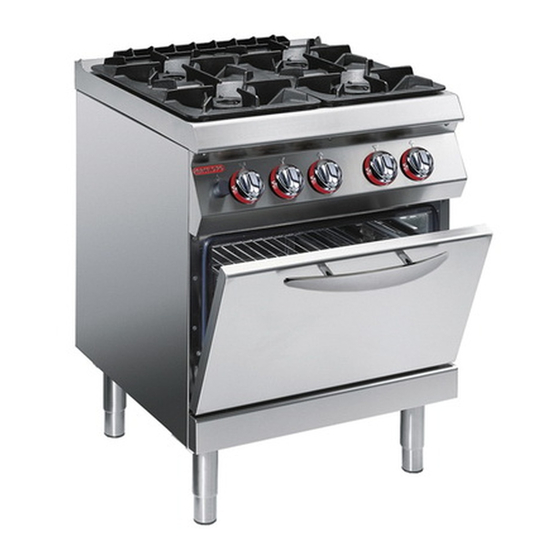
COCINA FUEGOS ABIERTOS + HORNO
OPEN BURNER RANGE + OVEN
CUISINIÈRE FEUX VIFS + FOUR
MANUALE D'USO E INSTALLAZIONE
BEDIEN- UND INSTALLATIONSHANDBUCH
MANUEL D'UTILISATION ET D'INSTALLATION
USE AND INSTALLATION MANUAL
MANUAL DE USO E INSTALACIÓN
1G1FA0E
1G1FA0EV
Italiano
English
Deutsch
Français
Español
Ed. 0
04/2008
3142900
IT
GB
DE
FR
ES
Publicidad
Capítulos
Tabla de contenido

Manuales relacionados para Angelo Po 1G1FA0E


Resumen de contenidos para Angelo Po 1G1FA0E
- Página 1 CUCINA FUOCHI APERTI + FORNO 1G1FA0E OPEN BURNER RANGE + OVEN GASHERD MIT OFFENEN FLAMMEN + BACKOFEN 1G1FA0EV CUISINIÈRE FEUX VIFS + FOUR COCINA FUEGOS ABIERTOS + HORNO MANUALE D’USO E INSTALLAZIONE USE AND INSTALLATION MANUAL BEDIEN- UND INSTALLATIONSHANDBUCH MANUEL D’UTILISATION ET D’INSTALLATION MANUAL DE USO E INSTALACIÓN...
-
Página 3: Tabla De Contenido
INDICE rif. capitoli pag. 1 INFORMAZIONI GENERALI ..........3 2 INFORMAZIONI TECNICHE ..........5 3 SICUREZZA ............... 7 PARTE 4 USO E FUNZIONAMENTO ..........9 5 MANUTENZIONI .............. 12 6 GUASTI ................14 7 MOVIMENTAZIONE E INSTALLAZIONE ......16 8 REGOLAZIONI ..............21 PARTE 9 SOSTITUZIONE PARTI ........... - Página 4 Ripristino apparecchiatura, 11 Sostituzione ugello bruciatore di pia- Trasporto, 16 Rubinetto gas, ingrassaggio, 23 no, 24 Ugello bruciatore di piano, sostitu- Rubinetto valvolato gas (bruciatori di Sostituzione ugello spia pilota brucia- zione, 24 piano), regolazione minimo, 21 tore di piano, 24 Ugello spia pilota bruciatore di piano, Sostituzione motore...
-
Página 5: Informazioni Generali
INFORMAZIONI GENERALI RACCOMANDAZIONI PER IL LETTORE parte: contiene tutte le informazioni ne- Per rintracciare facilmente gli argomenti specifici di interesse, consultare l’indice analitico posto all’ini- cessarie ai destinatari omogenei, cioè tutti gli zio del manuale. operatori esperti e autorizzati a movimentare, Questo manuale è... -
Página 6: Identificazione Costruttore E Apparecchiatura
IDENTIFICAZIONE COSTRUTTORE E APPARECCHIATURA ) Consumo gas La targhetta di identificazione raffigurata, è applica- ) Indicatore gas collaudo ta direttamente sull'apparecchiatura. In essa sono ) Tensione (V) riportati i riferimenti e tutte le indicazioni indispensa- ) Frequenza (Hz) bili alla sicurezza di esercizio. ) Potenza elettrica assorbita (W) Targa complementare ) Paese di utilizzo... -
Página 7: Informazioni Tecniche
INFORMAZIONI TECNICHE DESCRIZIONE GENERALE APPARECCHIATURA La cucina fuochi aperti con forno, d'ora innanzi de- finita apparecchiatura, è stata progettata e costruita per la preparazione e cottura di alimenti nell'ambito della ristorazione professionale. In funzione delle esigenze di utilizzo, l'apparecchia- 6 kW tura è... -
Página 8: Dati Tecnici
DATI TECNICI Vedi tabelle e “Scheda allacciamenti” in fondo al manuale. DISPOSITIVI DI SICUREZZA Anche se l'apparecchiatura è completa di tutti i di- spositivi di sicurezza, in fase di installazione e allac- ciamento essi dovranno, se necessario, essere integrati con altri in modo da rispettare le leggi vi- genti in materia. -
Página 9: Accessori A Richiesta
ACCESSORI A RICHIESTA A richiesta l'apparecchiatura può essere corredata dei seguenti accessori. A)Piastra bistecchiera liscia B)Piastra bistecchiera rigata C)Piastra di riduzione D)Kit per installazione "a ponte" (vedi pag. 18) IDM-39610800500.tif SICUREZZA NORME PER LA SICUREZZA Il costruttore, in fase di progettazione e costruzione, usi impropri può... - Página 10 In caso di inattività prolungata, oltre a scollegare Durante il lavaggio dell'apparecchiatura non dirige- tutte le linee di alimentazione, è necessario effet- re getti d'acqua in pressione sulle parti interne tuare una pulizia accurata di tutte le parti interne ed dell'apparecchiatura.
-
Página 11: Uso E Funzionamento
USO E FUNZIONAMENTO RACCOMANDAZIONI PER L’USO Importante L'incidenza degli infortuni derivanti dall'uso di principali. Attuare solo gli usi previsti dal co- apparecchiature dipende da molti fattori che struttore e non manomettere nessun disposi- non sempre si riescono a prevenire e control- tivo per ottenere prestazioni diverse da quelle lare. -
Página 12: Accensione E Spegnimento Bruciatori Di Piano
ACCENSIONE E SPEGNIMENTO BRUCIATORI DI PIANO Accensione 1 - Aprire il rubinetto alimentazione gas. 2 - Premere e ruotare la manopola (A) in senso an- tiorario (pos. 1) ed accendere la spia pilota. 3 - Mantenere premuta la manopola per circa 15 sec per consentire l'intervento della termocoppia. -
Página 13: Ripristino Apparecchiatura
2 - Ruotare la manopola (B) in posizione 1, fra la Spegnimento 4 - Ruotare la manopola (B) in posizione 3 per di- temperatura minima e massima e attendere il tempo di preriscaldamento prima di utilizzare il sattivare le resistenze di riscaldamento. Le spie di rete (D) e temperatura (C) si spengo- forno. -
Página 14: Consigli Per L'uso
CONSIGLI PER L’USO Al fine di garantire un corretto uso dell'apparecchia- – Utilizzare, per la cottura nel forno, le guide supe- tura, è bene applicare i seguenti consigli. riori per le torte e le guide inferiori per gli arrosti. – Utilizzare esclusivamente gli accessori indicati –... -
Página 15: Pulizia Apparecchiatura
PULIZIA APPARECCHIATURA Se si considera che l'apparecchiatura è utilizzata per Cautela - Avvertenza la preparazione di prodotti alimentari per l'uomo, è ne- Non usare prodotti che contengono sostanze cessario prestare particolare cura a tutto ciò che ri- dannose e pericolose per la salute delle per- guarda l'igiene e mantenere costantemente pulita sone (solventi, benzine, ecc.). -
Página 16: Pulizia Forno
PULIZIA FORNO Per questa operazione procedere nel modo indicato. 1 - Spegnere e lasciare raffreddare l'apparecchia- tura. 2 - Agire sull'interruttore sezionatore per disattiva- re l'alimentazione elettrica. 3 - Estrarre la suola (C) e la griglia (D) dal forno e pulirle accuratamente. - Página 17 Inconvenienti Cause Rimedi Chiudere il rubinetto Fuga occasionale dovuta a Odore di gas. alimentazione gas e aerare il spegnimento fiamma. locale. Verificare l’efficienza dei dispositivi di accensione. Accendere manualmente con fiamma libera. I dispositivi di accensione a scintilla non funzionano. La spia pilota non si accende.
-
Página 18: Movimentazione E Installazione
MOVIMENTAZIONE E INSTALLAZIONE RACCOMANDAZIONI PER LA MOVIMENTAZIONE E INSTALLAZIONE Importante Eseguire la movimentazione e l'installazio- ste operazioni dovrà, se necessario, orga- ne nel rispetto delle informazioni fornite dal nizzare "piano sicurezza" costruttore e riportate direttamente sull'im- salvaguardare l'incolumità delle persone ballo, sull'apparecchiatura e nelle istruzioni direttamente coinvolte. -
Página 19: Installazione Apparecchiatura
INSTALLAZIONE APPARECCHIATURA Tutte le fasi di installazione devono essere conside- rate sin dalla realizzazione del progetto generale. Prima di iniziare tali fasi, oltre alla definizione della zona di installazione, chi è autorizzato ad eseguire queste operazioni dovrà, se necessario, attuare un “piano di sicurezza”... -
Página 20: Montaggio Apparecchiature In Batteria
LIVELLAMENTO Agire sui piedi di appoggio (A) per livellare l'appa- recchiatura. IDM-39614401600.tif MONTAGGIO APPARECCHIATURE IN BATTERIA Per montare le apparecchiature in batteria (fianco a fianco) procedere nel modo indicato. 1 - Sfilare le manopole (A). 2 - Svitare le viti (C) e smontare i cruscotti (B). 3 - Applicare, sui bordi da accostare, del nastro adesivo di protezione. -
Página 21: Allacciamento Gas
ALLACCIAMENTO GAS Importante Chi è autorizzato ad effettuare tale operazio- ne deve possedere capacità ed esperienza acquisita e riconosciuta nel settore specifico, dovrà eseguire l'allacciamento a regola d'arte e tenere conto di tutti i requisiti normativi e le- gislativi. Ad allacciamento completato, prima di rendere operativa l'attrezzatura, si dovrà... -
Página 22: Allacciamento Elettrico
Cautela - Avvertenza l'utilizzo di materiale appropriato e prescritto. Prima di eseguire qualsiasi intervento disatti- L'apparecchiatura viene fornita con tensio- vare l'alimentazione elettrica generale. ne di funzionamento a 400V/3 (1G1FA0E) 400V/3N (1G1FA0EV),oppure su richiesta a 230V/3. Effettuare l'allacciamento dell'apparecchiatura alla rete di alimentazione nel modo indica- 1 - Installare, se non è... -
Página 23: Collaudo Apparecchiatura
COLLAUDO APPARECCHIATURA e, se necessario, effettuare la trasformazione Importante (vedi pag. 19). Prima della messa in servizio, occorre ese- 5 - Verificare la regolare accensione e combustio- guire il collaudo dell'impianto, per valutare ne dei bruciatori di piano. le condizioni operative di ogni singolo com- 6 - Verificare e, se necessario, regolare la pressio- ponente ed individuare le eventuali anoma- ne e la portata del gas al minimo e al massimo... - Página 24 5 - Dopo la regolazione sigillare la vite con vernice. Per questa operazione procedere nel modo indicato. 1 - Chiudere il rubinetto alimentazione gas 6 - Dopo la regolazione sigillare la vite con vernice. 2 - Sfilare le manopole (A). 7 - Rimontare il cruscotto (B) e le manopole (A) ad 3 - Svitare le viti (C) e smontare il cruscotto (B).
-
Página 25: Ingrassaggio Rubinetto Gas
INGRASSAGGIO RUBINETTO GAS Per questa operazione procedere nel modo indicato. sua sede e ruotarlo alcune volte. 8 - Sfilare il cono (F) per eliminare il grasso in ec- 1 - Chiudere il rubinetto alimentazione gas. 2 - Sfilare le manopole (A). cedenza. -
Página 26: Sostituzione Ugello Spia Pilota Bruciatore Di Piano
SOSTITUZIONE UGELLO SPIA PILOTA BRUCIATORE DI PIANO 5 - Estrarre l'ugello (E) e sostituirlo con quello Per questa operazione procedere nel modo indicato. 1 - Chiudere il rubinetto alimentazione gas. adatto al tipo di gas utilizzato (vedi tabella in 2 - Sfilare le manopole (A). fondo al manuale). - Página 27 CONTENTS ref. chapters page 1 GENERAL INFORMATION ..........3 2 TECHNICAL INFORMATION ..........5 3 SAFETY ................7 PART 4 USE AND OPERATION ............. 9 5 SERVICING ..............12 6 FAULT ................14 7 HANDLING AND INSTALLATION ........16 8 ADJUSTMENTS..............21 PART 9 REPLACING PARTS ............
- Página 28 Top burner primary air, adjustment, Transport, 16 Useful advice for use, 12 Troubleshooting, 14 Top burner, replacing pilot light noz- Unpacking and packaging, 16 zle, 24 Use, useful advice for, 12 Top burner, switching on and off, 10 - 2 - English...
-
Página 29: General Information
GENERAL INFORMATION INFORMATION FOR THE READER 2nd part: contains all the information neces- To find the specific topics of interest to you quickly, refer to the index at the start of the manual. sary for special categories of reader, i.e. all This manual is subdivided into two parts. -
Página 30: Procedure For Requesting Service
IDENTIFICATION OF CONSTRUCTOR AND APPLIANCE ) Testing gas indicator frame The nameplate shown here is fitted directly to the ) Voltage (V) appliance. It contains references and all essential ) Frequency (Hz) information for operating safety. ) Electricity power consumption (W) Extra nameplate ) Test voltage indicator ) Country of use... -
Página 31: Technical Information
TECHNICAL INFORMATION GENERAL DESCRIPTION OF APPLIANCE The open burner range with oven, referred to from now on as the appliance, is designed and construct- ed for preparing and cooking foods in the profes- sional catering sector. The appliance is produced in several versions to 6 kW meet varying user requirements. -
Página 32: Technical Data
TECHNICAL DATA See tables and "Connection chart" at the back of the manual. SAFETY DEVICES Although the appliance is complete with all safety devices, during installation and connection addi- tional devices must be added if necessary to com- ply with the relevant legal requirements. The illustration shows the position of the devices. -
Página 33: Optional Accessories
OPTIONAL ACCESSORIES The appliance can be equipped with the following accessories on request. A)Smooth radiant plate B)Ribbed radiant plate C)Reduction plate D)"Bridge" installation kit (see page 18) IDM-39610800500.tif SAFETY SAFETY REGULATIONS During design and construction, the constructor has the manufacturer. Improper use of the appli- paid special attention to factors which may cause ance may involve health and safety risks and risks to the health and safety of the people interact-... - Página 34 In case of lengthy downtimes, as well as discon- During routine use of the appliance, the Operator's necting all supply lines it is also essential to clean constant presence is required. all internal and external parts of the appliance and When washing the appliance do not point pressu- the surrounding environment thoroughly, complying rised water jets at internal parts.
-
Página 35: Use And Operation
USE AND OPERATION RECOMMENDATIONS FOR USE Important The rate of accidents deriving from the use and the main functions. Use only as intend- of appliances depends on many factors ed by the constructor and never tamper which cannot always be foreseen and con- with any device to obtain performance lev- trolled. -
Página 36: Switching The Top Burner On And Off
SWITCHING THE TOP BURNER ON AND OFF Lighting 1 - Turn on the gas supply tap. 2 - Press the knob (A) and turn it anti-clockwise (pos. 1) to light the pilot light. 3 - Keep the knob pressed for about 15 sec. to prime the thermocouple. -
Página 37: Resetting The Appliance
2 - Turn the knob (B) to setting 1, between the min- Turning off 4 - Turn the knob (B) to setting 3, to switch off the imum and maximum temperature, and wait for the warm-up time before using the oven. heating elements. -
Página 38: Recommendations For Servicing
USEFUL ADVICE FOR USE To ensure correct use of the appliance, the follow- – When cooking in the oven, use the top guides for ing rules should be adopted. cakes and the bottom guides for roasts. – Use only the accessories recommended by the –... -
Página 39: Cleaning Instructions
CLEANING INSTRUCTIONS Since the appliance is used for preparing foods for Caution - warning human consumption, special care must be paid to Never use products containing substances everything relating to hygiene, and the appliance harmful or hazardous for health (solvents, pe- and the entire surrounding environment must con- troleum spirits, etc.). -
Página 40: Cleaning Oven
CLEANING OVEN To carry out this operation, proceed as follows. 1 - Switch the appliance off and leave it to cool. 2 - Turn off the circuit-breaker to disconnect it from the electrical mains. 3 - Remove the bottom plate (C) and the grid (D) from the oven and clean them thoroughly. - Página 41 Faults Causes Remedies Occasional leak because flame Turn off the gas supply tap and Smell of gas has gone out ventilate the room Check that the ignition devices are in good working order Light by hand with a naked light The spark ignition devices are not working Important...
-
Página 42: Handling And Installation
HANDLING AND INSTALLATION RECOMMENDATIONS FOR HANDLING AND INSTALLATION Important When handling and installing the appliance use. If necessary, the person authorised to comply with the information provided by carry out these operations must organise a the constructor directly on the packaging, "safety plan"... -
Página 43: Installation Of The Appliance
INSTALLATION OF THE APPLIANCE All installation stages must be considered right from production of the general layout. Before starting these stages, as well as deciding the place of instal- lation, if necessary, the person authorised to carry out these operations must organise a "safety plan" to protect the people directly involved, and he must also ensure strict compliance with all legal require- ments, especially those relating to mobile work-... -
Página 44: Assembly Appliances In Banks
LEVELLING Adjust the floor-mounted feet (A) to level the appli- ance. IDM-39614401600.tif ASSEMBLY APPLIANCES IN BANKS To assemble appliances in banks (side by side) proceed as described below. 1 - Pull off the knob (A). 2 - Undo the screws (C) and remove the control panels (B). -
Página 45: Gas Connection
GAS CONNECTION Important Those authorised to carry out this opera- tion must have experience acquired and certified in the specific sector, must make the connection to the proper standards, and must comply with all the relevant regu- lations and legislation. Once the connec- tion has been made, before the appliance is put into operation a general check must be made to ensure there are no gas leaks. -
Página 46: Electrical Connection
Before doing any work, cut off the mains elec- propriate and specified materials. tricity supply. The appliance is supplied with operating voltage 400V3 (1G1FA0E) 400V/3N (1G1FA0EV) (230V/3 available on request). Connect the appliance to the mains electricity supply as fol- lows. -
Página 47: Testing Of The Appliance
TESTING OF THE APPLIANCE carry out the conversion procedure if necessary Important (see page 19). Before it is put into service, the system 5 - Check that the hob burners are igniting correct- must be tested to check the operating con- ly and their combustion. - Página 48 To carry out this operation, proceed as follows. at back of manual). 1 - Turn off the gas supply tap. 5 - After making the setting, seal the screw with 2 - Pull off the knob (A). paint. 3 - Undo the screws (C) and remove the control 6 - Replace the control panel (B) and the knobs (A) panel (B).
-
Página 49: Greasing The Gas Tap
GREASING THE GAS TAP 7 - Coat the cone with grease (F), fit it in its seat To carry out this operation, proceed as follows. 1 - Turn off the gas supply tap. and turn it a few times. 2 - Pull off the knob (A). 8 - Pull off the cone (F) to remove the excess 3 - Undo the screws (C) and remove the control grease. -
Página 50: Replacing The Top Burner Pilot Light Nozzle
REPLACING THE TOP BURNER PILOT LIGHT NOZZLE 5 - Remove the nozzle (E) and replace it with the To carry out this operation, proceed as follows. 1 - Turn off the gas supply tap. one suitable for the type of gas in use (see table 2 - Pull off the knob (A). - Página 51 INHALTSVERZEICHNIS Ref. Kapitel Seite 1 ALLGEMEINES ..............3 2 TECHNISCHE INFORMATIONEN ........5 3 SICHERHEIT ..............7 1. TEIL 4 GEBRAUCH UND BETRIEB ..........9 5 WARTUNG ............... 12 6 DEFEKTE ................. 14 7 HANDHABUNG UND INSTALLATION ......16 8 EINSTELLUNGEN ............21 2.
- Página 52 Technische Daten, 6 Umstellung der Gasversorgung, 19 Zündflammenbrenner des Kochstel- Testlauf zur Abnahme des Geräts, 21 lenbrenners, Austausch der Düse, 24 Verpackung und Auspacken, 16 Tipps für den Gebrauch, 12 Zweck des Handbuchs, 3 Transport, 16 Wartung, Empfehlungen für die, 12 Typenschild für Hersteller und Gerät, 4 - 2 - Deutsch...
-
Página 53: Allgemeines
ALLGEMEINES INFORMATIONEN FÜR DEN LESER 2. Teil: Diese Informationen wenden sich an Konsultieren Sie das Sachregister, das am Anfang des Handbuchs zu finden ist, um leichter unter be- eine bestimmte Zielgruppe. Sie sind für erfahre- stimmten Themen von besonderem Interesse ne Bediener bestimmt, die für Handhabung, nachschlagen zu können. -
Página 54: Typenschild Für Hersteller Und Gerät
TYPENSCHILD FÜR HERSTELLER UND GERÄT ) Testgasanzeige Das abgebildete Typenschild wird direkt auf dem ) Spannung (V) Gerät aufgebracht. Es enthält sämtliche Angaben ) Frequenz (Hz) und Hinweise, die für den sicheren Betrieb unerläs- ) Leistungsaufnahme (W) slich sind. ) Abnahmespannungsanzeige Ergänzungsschild ) WEEE-Symbol ) Benutzerland... -
Página 55: Technische Informationen
TECHNISCHE INFORMATIONEN ALLGEMEINE BESCHREIBUNG DES GERÄTS Der Gasherd mit offenen Flammen + Backofen, der im Folgenden als Gerät bezeichnet wird, wurde zum Zubereiten und Garen von Speisen in Restau- rantbetrieben projektiert und konstruiert. Das Gerät wird bedarfsabhängig in verschiedenen 6 kW Versionen hergestellt. -
Página 56: Technische Daten
TECHNISCHE DATEN Siehe Tabellen und „Anschlussschema" am Ende des Handbuchs. SICHERHEITSVORRICHTUNGEN Das Gerät wird zwar mit sämtlichen planmäßigen Sicherheitsvorrichtungen geliefert, es kann jedoch notwendig sein, während Installation und An- schluss ggf. weitere ergänzende Maßnahmen zu ergreifen, um den Anforderungen der einschlägi- gen geltenden Gesetze zu entsprechen. -
Página 57: Optionales Zubehör
OPTIONALES ZUBEHÖR Auf Wunsch kann das Gerät mit folgenden Zube- hörteilen ausgestattet werden. A)Glatte Bratplatte B)Gerillte Bratplatte C)Reduzierflammenschutzscheibe D)Einbausatz für Brückenmontage (siehe Seite 18). IDM-39610800500.tif SICHERHEIT SICHERHEITSVORSCHRIFTEN Der Hersteller hat bei Entwicklung und Fertigung Setzen Sie das Gerät nur für die vom Herstel- dieses Produkts besondere Sorgfalt auf Aspekte ler vorgesehenen Verwendungszwecke ein. - Página 58 Brenner ausgeschaltet sind, wobei die Bedienkne- vorschriften zu beachten sind. bel deaktiviert, und die Anschlussleitungen abge- Beim täglichen Gebrauch des Geräts ist die ständi- trennt sein müssen. ge Anwesenheit des Bedienungspersonals erfor- Im Falle einer längeren Stilllegung des Geräts ist derlich.
-
Página 59: Gebrauch Und Betrieb
GEBRAUCH UND BETRIEB EMPFEHLUNGEN FÜR DEN GEBRAUCH Wichtig Das Auftreten von Unfällen bei der Verwendung chen. Beschränken Sie sich auf die vom Her- von Geräten hängt von vielen Faktoren ab, die steller vorgesehenen Verwendungszwecke, nicht immer zu vermeiden und zu steuern sind. ohne Änderungen an den Vorrichtungen vorzu- Einige Unfälle können von unvorhersehbaren nehmen, um nicht vorgesehene Leistungen her-... -
Página 60: Ein- Und Ausschalten Der Kochstellenbrenner
EIN- UND AUSSCHALTEN DER KOCHSTELLENBRENNER Zündung 1 - Öffnen Sie den Gashahn. 2 - Den Schalter (A) niederdrücken und entgegen dem Uhrzeigersinn drehen (Pos. 1) und die Zündflamme zünden. 3 - Halten Sie den Bedienknebel etwa 15 Sekun- den lang gedrückt, damit das Thermoelement in Aktion treten kann. -
Página 61: Rücksetzen Des Geräts
2 - Den Schalter (B) in Schaltstellung 1 zwischen Min- Abschaltung 4 - Den Schalter (B) in Schaltstellung 3 um die dest- und Höchsttemperatur drehen und vor Be- nutzung des Backofens die Vorheizzeit abwarten. Heizwiderstände auszuschalten. Die Temperatur-Kontrollleuchte (C) und Stromzu- Stromzufuhr-Kontrollleuchte (D) und die Tem- fuhr-Kontrollleuchte (D) leuchtet auf, um zu si- peratur-Kontrollleuchte (C) gehen aus. -
Página 62: Tipps Für Den Gebrauch
TIPPS FÜR DEN GEBRAUCH Um eine korrekte Anwendung des Gerätes zu ge- – Die oberen Führungsschienen zum Backen von währleisten, sollten folgende Ratschläge befolgt Kuchen und die unteren Führungsschienen zum werden: Garen von Braten verwenden. – Verwenden Sie ausschließlich das vom Herstel- –... -
Página 63: Reinigung Des Geräts
REINIGUNG DES GERÄTS Da das Gerät zur Zubereitung von Speisen für den Vorsicht - Achtung Menschen eingesetzt wird, ist besondere Sorgfalt Verwenden Sie keine Produkte, die Stoffe ent- auf die Hygiene geboten. Das Gerät und dessen halten, welche für die menschliche Gesund- näheres Umfeld müssen konstant sauber gehalten heit schädlich... -
Página 64: Reinigung Des Backofens
REINIGUNG DES BACKOFENS Für diesen Vorgang in der angegebenen Weise verfahren. 1 - Das Gerät ausschalten und abkühlen lassen. 2 - Mit dem Trennschalter die Stromzufuhr unter- brechen. 3 - Den Rost (C) und das Bodenblech (D) aus dem Backofen nehmen und gründlich reinigen. 4 - Die Teile im Backofen von Verkrustungen reini- gen, die seine Funktionsfähigkeit beeinträchti- gen könnten. - Página 65 Probleme Ursachen Lösungen Beim Löschen der Flamme Schließen Sie den Gashahn und Gasgeruch. entstehender gelegentlicher lüften Sie den Raum. Gasaustritt. Überprüfen Sie die Funktionsfähigkeit der Zündeinrichtungen. Zünden Sie den Brenner manuell Die Funkenzündeinrichtungen mit freier Flamme. funktionieren nicht. Der Zündflammenbrenner lässt Wichtig sich nicht einschalten.
-
Página 66: Handhabung Und Installation
HANDHABUNG UND INSTALLATION EMPFEHLUNGEN FÜR DIE INSTALLATION UND HANDHABUNG Wichtig Beachten Sie die Hinweise des Herstellers, nen autorisierte Person wird bei Bedarf die direkt auf der Verpackung, auf dem Ge- einen „Sicherheitsplan" aufstellen müssen, rät selbst oder in der Gebrauchsanweisung um die Unversehrtheit der direkt an dem zu finden sind, wenn Sie das Gerät handha- Vorgang beteiligten Personen zu gewähr-... -
Página 67: Installation Des Geräts
INSTALLATION DES GERÄTS Es müssen sämtliche Phasen der Installation, schon von der Umsetzung des allgemeinen Projekts an, be- rücksichtigt werden. Die für diese Operationen autori- sierte Person wird vor Einleitung dieser Phasen den Installationsstandort bestimmen und bei Bedarf einen „Sicherheitsplan" aufstellen, um die Unversehrtheit der direkt am Vorgang beteiligten Personen zu gewährlei- sten und die gesetzlichen Bestimmungen zu befolgen. - Página 68 NIVELLIEREN Regulieren Sie die Füße (A), um das Gerät wasser- waagengerecht aufzustellen. IDM-39614401600.tif MONTAGE BEI REIHENAUFSTELLUNG Verfahren Sie folgendermaßen, um Geräte (neben- einander) in einer Reihe aufzustellen. 1 - Den Schalter (A) abziehen. 2 - Die Schrauben (C) ausschrauben und die Blen- den (B) ausbauen.
- Página 69 GASANSCHLUSS Wichtig Diese Arbeit darf nur von zugelassenen und erfahrenen Fachleuten ausgeführt wer- den. Der Anschluss muss fachgerecht und vorschriftsmäßig ausgeführt werden und allen einschlägigen gesetzlichen Bestim- mungen entsprechen. Nach Ausführung des Anschlusses muss vor der Inbetrieb- nahme des Geräts durch eine allgemeine Kontrolle sichergestellt werden, dass nir- gends Gas austritt.
- Página 70 Material ausgeführt werden. Vor Ausführung irgendeines Eingriffs die Das Gerät wird mit einer Betriebsspannung Hauptstromversorgung unterbrechen. von 400V/3N (1G1FA0E), 400V/3N (1G1FA0EV) oder auf Anfrage von 230V/3 geliefert. Den Anschluss des Geräts an das Stromnetz in der angege- benen Weise ausführen.
-
Página 71: Einstellungen
TESTLAUF ZUR ABNAHME DES GERÄTS 5 - Sicherstellen, dass Zündung und Verbrennung Wichtig der Kochstellenbrenner ordnungsgemäß erfol- gen. Vor der Inbetriebnahme muss ein Testlauf 6 - Überprüfen Sie Gasdruck und –durchsatz bei der Anlage durchgeführt werden, um den minimaler und maximaler Zufuhr und regulieren Betriebszustand jeder einzelnen Kompo- Sie, falls notwendig, die Einstellungen (siehe nente zu überprüfen und eventuelle An-... - Página 72 Für diesen Vorgang in der angegebenen Weise die verwendete Gasart geeignete Düse erset- verfahren. zen (siehe die Tabelle am Ende des Hand- 1 - Schließen Sie den Gaszufuhrhahn buchs). 2 - Den Schalter (A) abziehen. 5 - Versiegeln Sie die Schraube nach Abschluss 3 - Drehen Sie die Schrauben (C) heraus und der Einstellung mit Lack.
-
Página 73: Austausch Von Bauteile
SCHMIERUNG DES GASHAHNS 6 - Reinigen Sie den Kegel (F) und seinen Sitz. Für diesen Vorgang in der angegebenen Weise 7 - Den Kegel (F) mit Fett bestreichen, in seinen verfahren. 1 - Schließen Sie den Gaszufuhrhahn Sitz einsetzen und einige Male drehen. 2 - Den Schalter (A) abziehen. -
Página 74: Entsorgung Des Geräts
AUSTAUSCH DER DÜSE DES ZÜNDFLAMMENBRENNERS DES KOCHSTELLENBRENNERS 5 - Nehmen Sie die Düse (E) heraus und ersetzen Für diesen Vorgang in der angegebenen Weise verfahren. Sie sie mit dem für den betreffenden Gastyp 1 - Schließen Sie den Gaszufuhrhahn geeigneten Bauteil (siehe Tabelle am Ende des 2 - Den Schalter (A) abziehen. -
Página 75: Index Analytique
INDEX réf. chapitres page 1 INFORMATIONS GENERALES ......... 3 2 INFORMATIONS TECHNIQUES ........5 3 SÉCURITÉ ................. 7 PARTIE 4 UTILISATION ET FONCTIONNEMENT ......9 5 ENTRETIEN ..............12 6 PANNES ................14 7 MANUTENTION ET INSTALLATION ....... 16 8 RÉGLAGES ..............21 PARTIE 9 REMPLACEMENT DE PIÈCES ........ - Página 76 Sécurité, normes de, 7 Transport, 16 Veilleuse pilote du brûleur four- Signaux de sécurité et information, 6 neau, remplacement de la buse, 24 Utilisation, conseils d’, 12 Ventilation de la pièce, 17 Transformation de l’alimentation, 19 - 2 - Français...
-
Página 77: Informations Generales
INFORMATIONS GENERALES INFORMATIONS POUR LE LECTEUR 2e partie: elle contient toutes les informa- Pour retrouver facilement les sujets qui vous inté- ressent, consulter l’index analytique au début du tions nécessaires aux destinataires homogè- manuel. nes, c'est-à-dire tous les opérateurs experts Ce manuel est divisé... -
Página 78: Identification Du Fabricant Et De L'appareil
IDENTIFICATION DU FABRICANT ET DE L’APPAREIL ) Consommation de gaz La plaque d’identification représentée, est appli- ) Indicateur du gaz d’essai quée directement sur l'appareil. Elle reporte les ré- ) Tension (V) férences et les indications indispensables à la ) Fréquence (Hz) sécurité. -
Página 79: Informations Techniques
INFORMATIONS TECHNIQUES DESCRIPTION GÉNÉRALE DE L'APPAREIL Le fourneau feux vifs sur four, que l’on appellera maintenant appareil, a été conçu et fabriqué pour la préparation et la cuisson d’aliments dans le domai- ne de la restauration professionnelle. En fonction des exigences d'utilisation, l'appareil 6 kW est réalisé... -
Página 80: Données Techniques
DONNÉES TECHNIQUES Voir tableaux et « Fiche des raccordements » à la fin du manuel. DISPOSITIFS DE SÉCURITÉ Même si l’appareil est complet de tous les disposi- tifs de sécurité, lors de l’installation et du raccorde- ment, ils devront, si nécessaire, être intégrés avec d’autres pour respecter les lois en vigueur. -
Página 81: Accessoires Sur Demande
ACCESSOIRES SUR DEMANDE Sur demande l'appareil peut être équipé des acces- soires suivants. A)Plaque grille-viande lisse B)Plaque grille-viande nervurée C)Plaque de réduction D)Kit pour installation « en pont » (voir page 18) IDM-39610800500.tif SÉCURITÉ NORMES DE SÉCURITÉ Le fabricant, lors de la conception et de la fabrication, a ges impropres peut entraîner des risques pour la fait très attention aux aspects qui peuvent provoquer sécurité... - Página 82 En cas d’inutilisation prolongée, non seulement dé- Un opérateur doit être constamment présent pen- sactiver toutes les lignes d’alimentation, mais effec- dant l’utilisation quotidienne de l’appareil. tuer aussi un nettoyage soigné de l’intérieur et de Pendant le lavage de l’appareil ne pas diriger de l’extérieur de l’appareil et de ce qui l’entoure, selon jets d’eau sous pression sur les pièces intérieures.
-
Página 83: Utilisation Et Fonctionnement
UTILISATION ET FONCTIONNEMENT RECOMMANDATIONS POUR L'UTILISATION Important L'incidence des accidents dérivant de l'utilisa- fonctions principales. Utiliser seulement com- tion d'appareils dépend de beaucoup de fac- me prévu par le fabricant et ne modifier aucun teurs que l'on ne peut pas toujours prévenir et dispositif pour obtenir des performances dif- contrôler. -
Página 84: Allumage Et Extinction Brûleurs Fourneau
ALLUMAGE ET EXTINCTION BRÛLEURS FOURNEAU Allumage 1 - Ouvrir le robinet d’alimentation du gaz. 2 - Pousser et tourner la manette (A) en sens anti- horaire (pos. 1) pour allumer la veilleuse pilote. 3 - Continuer à appuyer sur la manette pendant environ 15 s pour permettre l’intervention du thermocouple. -
Página 85: Rétablissement Des Fonctions De L'appareil
Extinction ture minimale et maximale, et attendre le temps 4 - Tourner la manette (B) sur 3 pour désactiver de préchauffage avant d’utiliser le four. Le voyant (C) et (D) s’allume pour signaler que les résistances de chauffe. Les voyants de réseau (D) et de la température le four n’est pas à... -
Página 86: Conseils D'utilisation
CONSEILS D’UTILISATION Afin de garantir une utilisation correcte de l’appa- – Utiliser, pour la cuisson dans le four, les guides reil, suivre ces conseils. supérieurs pour les tartes et les guides inférieurs – Utiliser exclusivement les accessoires indiqués pour les rôtis. par le fabricant. -
Página 87: Nettoyage De L'appareil
NETTOYAGE DE L’APPAREIL Étant donné que l'appareil est utilisé pour la prépa- Attention ration de produits alimentaires pour l'homme, il faut Ne pas utiliser de produits qui contiennent faire attention à tout ce qui concerne l'hygiène; l'ap- des substances dangereuses pour la santé pareil et tout ce qui l'entoure doivent toujours être des personnes (solvants, essences, etc.). -
Página 88: Nettoyage Du Four
NETTOYAGE DU FOUR Pour cette opération, procéder comme suit. 1 - Eteindre et laisser refroidir l’appareil. 2 - Agir sur l’interrupteur sectionneur pour désacti- ver l’alimentation électrique. 3 - Extraire la sole (C) et la grille (D) du four et les nettoyer soigneusement. - Página 89 Inconvénients Causes Solutions Fuite occasionnelle due à Fermer le robinet d’alimentation Odeur de gaz. l’extinction de la flamme, du gaz et aérer la pièce. Vérifier l’efficacité des dispositifs d’allumage. Allumer manuellement avec flamme nue. Les dispositifs d’allumage à étincelle ne fonctionnent pas. La veilleuse pilote ne s’allume Important pas.
-
Página 90: Manutention Et Installation
MANUTENTION ET INSTALLATION RECOMMANDATIONS POUR LA MANUTENTION ET L’INSTALLATION Important Effectuer la manutention et l’installation en effectuer ces opérations devra, si nécessai- respectant les informations fournies par le re, organiser un « plan de sécurité » pour fabricant, reportées directement sur l’em- sauvegarder la sécurité... -
Página 91: Mise En Place De L'appareil
MISE EN PLACE DE L’APPAREIL Toutes les phases de mise en place doivent être prises en considération, dès la réalisation du projet général. Avant de commencer ces phases, outre la définition de la zone de mise en place, celui qui est autorisé... -
Página 92: Mise À Niveau
MISE À NIVEAU Agir sur les pieds d’appui (A) pour mettre de niveau l’appareil. IDM-39614401600.tif MONTAGE DES APPAREILS EN BATTERIE Pour monter les appareils en batterie (les uns à côté des autres), procéder comme suit. 1 - Enlever la manette (A). 2 - Dévisser les vis (C) et démonter les tableaux de commandes (B). -
Página 93: Raccordement Du Gaz
RACCORDEMENT DU GAZ Important La personne autorisée à effectuer cette opéra- tion devra avoir les capacités et l'expérience acquise et reconnue dans le secteur spécifi- que; elle devra effectuer le raccordement dans les règles de l'art et tenir compte de tou- tes les exigences imposées par les normes et les lois. -
Página 94: Branchement Électrique
Avant toute intervention, couper l’alimenta- L'appareil est fourni avec tension de fonc- tion électrique générale. tionnement à 400V3 (1G1FA0E) 400V/3N (1G1FA0EV), ou sur demande à 230V/3. Effectuer le branchement de l'appareil au réseau électrique d'alimentation comme suit. - Página 95 ESSAI DE L’APPAREIL nécessaire, effectuer la transformation (voir Important page 19). Avant la mise en service, l’essai de l’instal- 5 - Vérifier l’allumage régulier et la combustion des lation doit être fait pour évaluer les condi- brûleurs de table. tions opérationnelles chaque 6 - Vérifier et, si nécessaire, régler la pression et le...
- Página 96 Pour cette opération, procéder comme suit. fin du manuel). 1 - Fermer le robinet d’alimentation du gaz. 5 - Après le réglage sceller la vis avec du vernis. 2 - Enlever la manette (A). 6 - Remonter le tableau de commandes (B) et les 3 - Dévisser les vis (C) et démonter le tableau de manettes (A) lorsque l’opération est terminée.
-
Página 97: Remplacement De Pièces
GRAISSAGE DU ROBINET À GAZ 7 - Graisser le cône (F), le remettre dans son loge- Pour cette opération, procéder comme suit. 1 - Fermer le robinet d’alimentation du gaz. ment et le tourner plusieurs fois. 2 - Enlever la manette (A). 8 - Extraire le cône (F) pour éliminer la graisse en 3 - Dévisser les vis (C) et démonter le tableau de surplus. -
Página 98: Élimination De L'appareil
REMPLACEMENT DE LA BUSE VEILLEUSE PILOTE DU BRÛLEUR FOURNEAU 5 - Enlever la buse (E) et la remplacer par celle Pour cette opération, procéder comme suit. 1 - Fermer le robinet d’alimentation du gaz. adaptée au type de gaz utilisé (voir tableau à la 2 - Enlever la manette (A). - Página 99 ÍNDICE ref. capítulos pág 1 INFORMACIONES DE CARÁCTER GENERAL ....3 2 INFORMACIONES DE CARÁCTER TÉCNICO ....5 3 SEGURIDAD ..............7 PARTE 4 USO Y FUNCIONAMIENTO ..........9 5 MANTENIMIENTO ............12 6 AVERÍAS ................14 7 DESPLAZAMIENTO E INSTALACIÓN ......16 8 REGULACIONES .............
- Página 100 efectuar las, 21 quemador de plano, 24 Transformación alimentación, 19 Sustitución piezas, recomendaciones Transporte, 16 Seguridad, dispositivos de, 6 para efectuar la, 23 Seguridad, normas de, 7 Uso, consejos para el, 12 Sustitución motor ventilador,24 Señalizaciones de seguridad e infor- Ventilación del ambiente, 17 mación, 6 Testigo piloto quemador de plano,...
-
Página 101: Informaciones De Carácter General
INFORMACIONES DE CARÁCTER GENERAL INFORMACIONES PREVIAS 2a parte: contiene todas las informaciones Para ubicar fácilmente los temas específicos de in- terés, consúltese el índice analítico que se encuen- necesarias para destinatarios homogéneos, tra al inicio del manual. esto es, todos los operadores expertos y au- Este manual comprende dos partes. -
Página 102: Identificación Fabricante Y Equipo
IDENTIFICACIÓN FABRICANTE Y EQUIPO ) Indicador gas prueba de funcionamiento La placa de identificación fijada directamente en el ) Tensión (V) equipo reproduce todas las referencias e indicacio- ) Frecuencia (Hz) nes indispensables para la seguridad de servicio. ) Potencia eléctrica absorbida (W) Placa complementaria ) Indicador tensión de prueba ) País de uso... -
Página 103: Informaciones De Carácter Técnico
INFORMACIONES DE CARÁCTER TÉCNICO DESCRIPCIÓN GENERAL DEL EQUIPO La cocina fuegos abiertos con horno, que de ahora en adelante llamaremos aparato, ha sido proyecta- da y fabricada para la preparación y la cocción de alimentos en el sector de la restauración profesio- nal. -
Página 104: Datos Técnicos
DATOS TÉCNICOS Véase tablas y "Ficha de enlaces" al final del ma- nual. DISPOSITIVOS DE SEGURIDAD Aunque el equipo cuente con todos los dispositivos de seguridad, en los casos en que así lo determi- nen las leyes vigentes en materia, se deberá com- plementar con otros dispositivos en las fases de instalación y enlace. -
Página 105: Accesorios Bajo Pedido
ACCESORIOS BAJO PEDIDO Bajo pedido, el equipo puede ser suministrado con los accesorios que a continuación se indican. A)Plancha de cocción lisa B)Plancha de cocción ranurada C)Plancha de reducción D)Kit para la instalación "de puente" (véase pág. 18). IDM-39610800500.tif SEGURIDAD NORMAS DE SEGURIDAD Durante las fases de diseño y producción el fabricante riesgos en cuanto a seguridad y salud de las per-... -
Página 106: Normas De Seguridad Relativas Al Impacto Ambiental
En caso de períodos prolongados de inactividad, Durante el uso cotidiano del aparato se requiere la además de desconectar todas las líneas de alimen- presencia constante del operador. tación, es necesario limpiar prolijamente todas las Durante el lavado del aparato no dirigir chorros de partes internas y externas del equipo y del ambien- agua a presión hacia sus partes internas. -
Página 107: Uso Y Funcionamiento
USO Y FUNCIONAMIENTO RECOMENDACIONES DE USO Importante El porcentaje de accidentes derivados del uso de principales. Se deben ejecutar sólo operaciones equipos depende de muchos factores que no propias de los usos previstos por el fabricante. No siempre se logran prevenir y controlar. Algunos alterar los equipos con el fin de obtener prestacio- accidentes pueden depender de factores ambien- nes diferentes de las previstas. -
Página 108: Encendido Y Apagado Quemadores De Plano
ENCENDIDO Y APAGADO QUEMADORES DE PLANO Encendido 1 - Abrir el grifo de alimentación del gas. 2 - Presionar y girar el mando (A) en sentido anti- horario (pos. 1) y encender el testigo piloto. 3 - Mantener presionado el mando durante aprox. 15 s para obtener la intervención del termopar. -
Página 109: Reactivación Aparato
2 - Situar el mando (B) en posición 1, entre la tem- Apagado 4 - Situar el mando (B) en posición 3 a fin de des- peratura mínima y la máxima; esperar el tiempo de precalentamiento antes de utilizar el horno. activar las resistencias de calentamiento. -
Página 110: Consejos Para El Uso
CONSEJOS PARA EL USO A fin de garantizar un uso correcto del equipo, apli- – Para cocer en el horno utilice las guías superio- car las siguientes recomendaciones. res para las tartas y las guías inferiores para los – Utilizar exclusivamente los accesorios indicados asados. -
Página 111: Limpieza Aparato
LIMPIEZA APARATO Atendida la circunstancia de que el equipo es utili- Precaución - advertencia zado para la preparación de productos alimenticios No usar productos que contengan sustancias para el consumo humano, es necesario prestar es- nocivas y/o peligrosas para la salud de las pecial atención a todo lo referente a la higiene, personas (disolventes, bencinas, etc.). -
Página 112: Control De La Presión Del Gas
LIMPIEZA HORNO Para efectuar esta operación, aplicar las siguientes instrucciones. 1 - Apagar y dejar enfriar el aparato. 2 - Operar con el interruptor aislador para inte- rrumpir la alimentación eléctrica. 3 - Extraer la solera (C) y la rejilla (D) del horno y limpiarlas esmeradamente. - Página 113 Inconvenientes Causas Remedios Fuga ocasional debida al Cerrar el grifo de alimentación del Olor de gas. apagado de la llama. gas y ventilar el local. Controlar la eficacia de los dispositivos de encendido. Encender manualmente con la llama libre. Los dispositivos de encendido con chispa no funcionan.
-
Página 114: Desplazamiento E Instalación
DESPLAZAMIENTO E INSTALACIÓN RECOMENDACIONES PARA EL DESPLAZAMIENTO Y LA INSTALACIÓN Importante Efectuar el desplazamiento e instalación rizada para efectuar estas operaciones de- respetando las indicaciones proporciona- berá, si fuera necesario, organizar un "plan das por el fabricante, reproducidas directa- de seguridad", a fin de salvaguardar la in- mente sobre el embalaje, en el equipo y en columidad de las personas directamente las instrucciones de uso. -
Página 115: Instalación Del Equipo
INSTALACIÓN DEL EQUIPO Durante la realización del proyecto general, deben ser consideradas todas las fases de la instalación. Antes de comenzar dichas fases, además de esta- blecer la zona de instalación, la persona autorizada a efectuar estas operaciones deberá, si fuera nece- sario, aplicar un "plan de seguridad"... -
Página 116: Nivelación
NIVELACIÓN Operar con las patas de apoyo (A) para nivelar el equipo. IDM-39614401600.tif MONTAJE DE EQUIPOS EN BATERÍA Para montar los equipos en batería (uno al lado del otro) aplicar las siguientes instrucciones. 1 - Retirar el mando (A). 2 - Desenroscar los tornillos (C) y desmontar los paneles de mando (B). -
Página 117: Transformación Alimentación
ENLACE GAS Importante El personal autorizado para ejecutar esta operación debe poseer capacidad y haber adquirido experiencia efectiva en el sector específico; la conexión deberá ejecutarse respetando rigurosamente todos los requi- sitos establecidos por las normativas vigen- tes. Una vez efectuada la conexión, antes de poner en funcionamiento el aparato se de- berá... -
Página 118: Conexión Eléctrica
El aparato se suministra con tensión de fun- ral. cionamiento de 400V/3(1G1FA0E) 400V3N (1G1FA0EV) o bien, bajo pedido, de 230V/3. Conectar el aparato a la red eléctrica de alimentación res- petando las siguientes instruc- ciones. -
Página 119: Prueba De Funcionamiento Del Equipo
PRUEBA DE FUNCIONAMIENTO DEL EQUIPO cionamiento del equipo y, en caso contrario, efec- Importante tuar la respectiva transformación (véase pág. 19). Antes de la puesta en servicio debe efec- 5 - Controlar el encendido y la combustión de los tuarse la prueba de funcionamiento del sis- quemadores de la encimera. -
Página 120: Regulación Aire Primario Quemador De Plano
Para efectuar esta operación, aplicar las siguientes sea adecuado para el tipo de gas utilizado instrucciones. (véase tabla al final del manual). 1 - Cerrar el grifo de alimentación del gas. 5 - Una vez efectuada la regulación sellar el torni- 2 - Retirar el mando (A). -
Página 121: Engrasar Del Grifo Gas
ENGRASAR DEL GRIFO GAS 6 - Limpiar el cono (F) y también su alojamiento. Para efectuar esta operación, aplicar las siguientes 7 - Aplicar grasa en el cono (F), volver a instalarlo instrucciones. 1 - Cerrar el grifo de alimentación del gas. en su alojamiento, girándolo varias veces. -
Página 122: Desguace Del Equipo
SUSTITUCIÓN INYECTOR TESTIGO PILOTO QUEMADOR DE PLANO 4 - Retirar el tubo (D). Para efectuar esta operación, aplicar las siguientes 5 - Extraer el inyector (E) y sustituirlo por otro que instrucciones. 1 - Cerrar el grifo de alimentación del gas. sea adecuado para el tipo de gas utilizado 2 - Retirar el mando (A). - Página 123 (Min. 1,3 kW) (Min. 1,9 kW) Tension Fréquence Courant Tensión Frecuencia Corriente N. 1 N. 3 1G1FA0E 2,33 m /h 2,71 m /h 1,74 Kg/h 1,71 Kg/h N. 1 5,2 kW 400 V3~ 50-60 Hz 11,5 A N. 1 N. 3...
- Página 124 Bruciatori di piano Dati elettrici - Electrical data Top burners - Consumo gas - Gas consumption Daten zur Elektrik Kochstellenbrenner - Gasverbrauch - Consommation de gaz Données électriques Modello Forno Potenza Brûleurs fourneau - Consumo de gas Datos eléctricos Model Oven Power Quemadores de plano...
- Página 125 SCHEMA ELETTRICO (1G1FA0E - 400V/3) - ELECTRICAL SYSTEM DIAGRAM (1G1FA0E - 400V/3) - ELEKTRISCHER SCHALTPLAN (1G1FA0E - 400V/3) - SCHÉMA ÉLECTRIQUE (1G1FA0E - 400V/3) - ESQUEMA ELÉCTRICO (1G1FA0E - 400V/3) 1) Morsettiera - Terminal board - Klemmenbrett - Plaque à bornes - Regleta de...
- Página 126 SCHEMA ELETTRICO (1G1FA0E - 230V/3) - ELECTRICAL SYSTEM DIAGRAM (1G1FA0E - 230V/3) - ELEKTRISCHER SCHALTPLAN (1G1FA0E - 230V/3) - SCHÉMA ÉLECTRIQUE (1G1FA0E - 230V/3) - ESQUEMA ELÉCTRICO (1G1FA0E - 230V/3) 1) Morsettiera - Terminal board - Klemmenbrett - Plaque à bornes - Regleta de...
- Página 127 SCHEMA ELETTRICO (1G1FA0EV - 400V/3N) - ELECTRICAL SYSTEM DIAGRAM (1G1FA0EV - 400V/3N) - ELEKTRISCHER SCHALTPLAN - (1G1FA0EV - 400V/3N) - SCHÉMA ÉLECTRIQUE (1G1FA0EV - 400V/3N) - ESQUEMA ELÉCTRICO (1G1FA0EV - 400V/3N) 1) Morsettiera - Terminal board - Klemmenbrett - Plaque à bornes - Regleta de seguridad 7) Termostato di sovratemperatura - Overheating thermostat - Thermostat de conexión...
- Página 128 SCHEMA ELETTRICO (1G1FA0EV - 230V/3) - ELECTRICAL SYSTEM DIAGRAM (1G1FA0EV - 230V/3) - ELEKTRISCHER SCHALTPLAN - (1G1FA0EV - 230V/3) - SCHÉMA ÉLECTRIQUE (1G1FA0EV - 230V/3) - ESQUEMA ELÉCTRICO (1G1FA0EV - 230V/3) 1) Morsettiera - Terminal board - Klemmenbrett - Plaque à bornes - Regleta de seguridad 7) Termostato di sovratemperatura - Overheating thermostat - Thermostat de conexión...
- Página 129 Tabella iniettori bruciatore di piano ø80 - Table of top burner injectors ø80 - Tabelle: Düsen für Kochstellenbrenner ø80 Tableau des injecteurs du brûleur fourneau ø80 - Tabla inyectores quemador de plano ø80 ø (4) ø (5) ø (6) ø (8) p (3) mbar p (7) mbar Pen mbar Qn max kW...
- Página 130 Tabella iniettori bruciatore di piano ø80 - Table of top burner injectors ø80 - Tabelle: Düsen für Kochstellenbrenner ø80 Tableau des injecteurs du brûleur fourneau ø80 - Tabla inyectores quemador de plano ø80 ø (4) ø (5) ø (6) ø (8) p (3) mbar p (7) mbar Pen mbar Qn max kW...
- Página 131 Tabella iniettori bruciatore di piano ø110 - Table of top burner injectors ø110 - Tabelle: Düsen für Kochstellenbrenner ø110 Tableau des injecteurs du brûleur fourneau ø110 - Tabla inyectores quemador de plano ø110 ø (4) ø (5) ø (6) ø (8) p (3) mbar p (7) mbar Pen mbar Qn max kW...
- Página 132 Tabella iniettori bruciatore di piano ø110 - Table of top burner injectors ø110 - Tabelle: Düsen für Kochstellenbrenner ø110 Tableau des injecteurs du brûleur fourneau ø110 - Tabla inyectores quemador de plano ø110 ø (4) ø (5) ø (6) ø (8) p (3) mbar p (7) mbar Pen mbar Qn max kW...
- Página 133 Tabella caratteristiche gas - Table of gas characteristics - Tabelle der Gas-Eigenschaften Tableau des caractéristiques du gaz - Tabla características gas Potere calorifero inferiore (Hi) Famiglia Tipo di gas Indice Wobbe (MJ/m Net calorific value (Hi) Group Gas type Wobbe index (MJ/m Unterer Heizwert (Hi) Familie Gastypen...