Tabla de contenido
Publicidad
Idiomas disponibles
Idiomas disponibles
Enlaces rápidos
Harbor Breeze® is a registered trademark
of LF, LLC. All Rights Reserved.
Federal regulations require ceiling fans with light kits manufactured or imported after
January 1, 2009, to limit total wattage consumed by the light kit to 190W. Therefore,
this fan is equipped with a wattage limiting device. If you lamp this fan's light kit with
bulbs totaling more than 190W, the wattage limiting device will reduce the watts
consumed to 190W.
WARNINGS
• READ AND SAVE THESE INSTRUCTIONS.
• Read this manual carefully and completely before attempting to assemble, install or operate this product.
• Be sure you read and understand the Safety Information on page 3 of these instructions.
• Do not discard fan carton or foam inserts. Should this fan need to be returned to the factory for repairs, it must be
shipped in its original packaging to ensure proper protection against damage that might exceed the initial cause for
return.
•
CAUTION: Before proceeding, be sure to shut off electricity at main switch or circuit breaker in order to avoid
electrical shock.
•
WARNING: To reduce the risk of fire or electric shock, do not use this fan with variable speed switch.
•
WARNING: To reduce the risk of fire, electric shock, or personal injury, do not bend the blade arms when
installing them, balancing the blades, or cleaning the fan. Do not insert foreign objects between the rotating fan
blades. Mount to outlet box marked "ACCEPTABLE FOR FAN SUPPORT" and use mounting screws provided with
the outlet box. Most outlet boxes commonly used for the support of lighting fixtures are not acceptable for fan
support and may need to be replaced. Consult a qualified electrician if in doubt.
•
DANGER: If using this fan in a DAMP location, this fan must be connected to a supply circuit that is
protected by a Ground Fault Circuit Interrupter (GFCI) to reduce the risk of personal injury, electrical shock or
death.
Questions, problems, missing parts? Before returning to your retailer, call or contact our customer service
department at 1-800-527-1292, 8:30 a.m.-5:00 p.m., CST, Monday-Friday or www.litexfans.com.
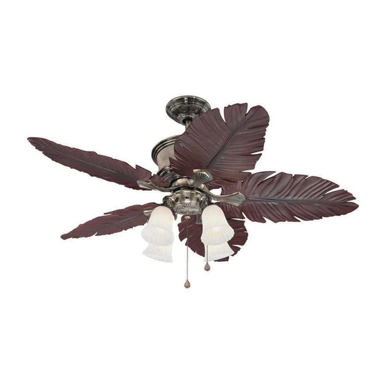
KIAWAH/CEILING FAN
KIAWAH/VENTILADOR DE TECHO
1
ITEM/ARTICULO #0065388
(página 12)
MODEL/MODELO #E-PAR52CB5C
LISTED
For
Damp Location
E192641
Publicidad
Capítulos
Tabla de contenido

Manuales relacionados para Harbor Breeze E-PAR52CB5C


Resumen de contenidos para Harbor Breeze E-PAR52CB5C
- Página 1 KIAWAH/VENTILADOR DE TECHO (página 12) MODEL/MODELO #E-PAR52CB5C Harbor Breeze® is a registered trademark of LF, LLC. All Rights Reserved. Federal regulations require ceiling fans with light kits manufactured or imported after January 1, 2009, to limit total wattage consumed by the light kit to 190W. Therefore, this fan is equipped with a wattage limiting device.
-
Página 2: Tabla De Contenido
TABLE OF CONTENTS Safety Information ......…………………………………………………………………………...……..….3 Package Contents ......…………………………………………………………………..……..…..…..4 Preparation ........….…………………..……………………….…………….………………..5 Initial Installation ..........……………………...…………………………………………...….5 Normal or Angle Style Fan Mounting ......…………………………..………………………….....6 Wiring ......................………………………………..6 - 7 Final Installation ....………………….…………….……………………….…………..….…....8 - 9 Fan Operation ....................…………………………………..….9 Care and Maintenance .......………………………………………………………………..…………..….10 Troubleshooting ...........………...………………………….……………..………..…..…10 Warranty ......…………………………………….………………………………………......11... -
Página 3: Safety Information
SAFETY INFORMATION READ AND SAVE THESE INSTRUCTIONS Please read and understand this entire manual before attempting to assemble, install or operate the product. If you have any questions regarding the product, please call customer service at 1-800-527-1292, 8:30 a.m.-5:00 p.m., CST, Monday-Friday. -
Página 4: Package Contents
PACKAGE CONTENTS Part Description Quantity Downrod Canopy Mounting Bracket (attached to canopy) Motor Housing Switch Housing Switch Housing Plate Yoke Cover Blade Arm Glass Shade Blade Motor Screw ( in motor and in hardware pack 3/16 Blade Screw (in hardware pack) 5.4M/M Lock Washer ( in motor and attached to motor screw in hardware pack... -
Página 5: Preparation
PREPARATION 1. Before beginning assembly and installation of product, make sure all parts are present. Compare parts with "Package Contents" list and diagrams on the previous page. If any part is missing or damaged, do not attempt to assemble, install or operate the product. Contact customer service for replacement parts as indicated at the bottom of page 4. -
Página 6: Normal Or Angle Style Fan Mounting
NORMAL OR ANGLE STYLE FAN MOUNTING 1. Locate safety cable (U) at top of motor housing (D). Remove vice (V) from safety cable (U) by loosening screw and nut. [Fig. 1A] Insert Screw downrod (A) through canopy (B), canopy cover (Y) and yoke cover (G). [Note: Canopy cover (Y) must be turned with the shiny side toward the motor housing (D)]. -
Página 7: Wiring
WIRING (continued from previous page) FAN AND LIGHT CONTROLLED BY CHAIN. 1. Choose wiring diagram [Fig. 1A, Fig. 1B or Fig. 1C] that fits your Fig. 1A BLACK (POWER) situation and make appropriate wiring connections as follows: (Make special note of Step 3 below while wiring.) WHITE (NEUTRAL) GROUND 1A. -
Página 8: Final Installation
FINAL INSTALLATION (continued on next page) 1. Locate two canopy mounting screws (P) on underside of mounting bracket (C) and remove canopy mounting screw (P) closest to the open end of the hanging bracket (C). Partially loosen the other canopy mounting screw (P). -
Página 9: Fan Operation
FINAL INSTALLATION (continued from previous page) 9. Install four candelabra base 40 watt max. bulbs (X) included. [Fig. 9] Important: When replacing bulbs, allow bulb(s) and glass shade(s) to cool before touching them. Fig. 9 10. Pull chain extensions (S) supplied in one of the hardware packs or custom pull chain extensions (not included) may be attached to fan and light pull chains. -
Página 10: Care And Maintenance
CARE AND MAINTENANCE At least twice each year, lower canopy (B) to check downrod (A) assembly, and then tighten all screws on the fan. Clean motor housing (D) with only a soft brush or lint-free cloth to avoid scratching the finish. Clean blades (J) with a lint-free cloth. -
Página 11: Warranty
TROUBLESHOOTING (continued from previous page) Problem (cont.) Possible Cause (cont.) Corrective Action (cont.) Lights appear dimmer than 1. Fan is lamped with more than 190W 1. Lamp light kit with bulbs that total no they should. and wattage limiting device is reducing more than 190W. -
Página 12: Kiawah/Ventilador De Techo
ARTICULO #0065388 KIAWAH/VENTILADOR DE TECHO MODELO #E-PAR52CB5C Harbor Breeze® es marca registrada de LF, LLC. Reservados todos los derechos. El reglamento federal requiere que un ventilador de techo con juego de luz fabricado o importado después del 1 de enero del 2009 limite el vatiaje total que consume el juego de luz a 190W. - Página 13 INDICE DE MATERIAS Información de seguridad ..…………………………………………………......……...……..… 14 Contenido del paquete ....…………………………………………………………………………..……. 15 Preparación ..........….…………………..……………………….…………….…..…. 16 Instalación inicial ..........…………………………………………………………………...… .16 Estilo de montaje del ventilador normal o en ángulo ........……..……………………..…..17 Conexión de los cables .........………………………..…………………………...…. 17 - 19 Instalación final ....……………….…………….…….………………….……...…….……....……..19 - 20 Funcionamiento del ventilador ..............…………………………………..…...
-
Página 14: Información De Seguridad
INFORMACION DE SEGURIDAD POR FAVOR LEA Y GUARDE ESTAS INSTRUCCIONES Por favor lea el instructivo entero antes de tratar de ensamblar, instalar o hacer funcionar el producto. Si tiene alguna pregunta acerca del producto, por favor llame al servicio al cliente al 1-800-527-1292, de 8:30 a.m. a 5:00 p.m., hora central, de lunes a viernes. -
Página 15: Contenido Del Paquete
CONTENIDO DEL PAQUETE Pieza Descripción Cantidad Vástago Cubierta Soporte de montaje (sujetado a la cubierta) Bastidor del motor Caja del interruptor Placa de la caja del interruptor Cubierta del yugo Brazo para la paleta Pantalla de vidrio Paleta Tornillo del motor (en el motor y en el paquete de artículos de ferretería) Tornillo para la paleta 4,76 mm... -
Página 16: Preparación
PREPARACION 1. Antes de empezar con el ensamblaje e instalación del producto, asegúrese de tener todas las piezas. Compare las piezas con la lista y los diagramas del "Contenido del paquete" en la página anterior. Si falta alguna pieza o se encuentra dañada, no trate de ensamblar, instalar o hacer funcionar el producto. -
Página 17: Estilo De Montaje Del Ventilador Normal O En Ángulo
ESTILO DE MONTAJE DEL VENTILADOR NORMAL O EN ANGULO tuerca 1. Localice el cable de seguridad (U) en la parte superior del bastidor del motor (D). Quite el seguro (V) del cable de seguridad (U) aflojando tornillo el tornillo y la tuerca. [Fig. 1A] Introduzca el vástago (A) en la cubierta (B), decoración para la cubierta (Y) y la cubierta del yugo (G). - Página 18 CONEXION DE LOS CABLES (continúa de la página anterior) VENTILADOR Y LUZ CONTROLADOS POR CADENA. 1. Escoja el diagrama de instalación eléctrica [Fig. 1A, Fig. 1B o Fig. 1A NEGRO (POSITIVO) Fig. 1C] que corresponde a su situación y haga las conexiones BLANCO (NEUTRAL) apropiadas según lo que sigue: (Tenga muy en cuenta el paso 3 a continuación al hacer la conexión de cables.)
-
Página 19: Instalación Final
CONEXION DE LOS CABLES (continúa de la página anterior) 4. Atornille los conectores para cable (O) en el sentido de las agujas del reloj. Ponga cinta aislante en cada conector para cable (O) hasta llegar al cable como se muestra en la Fig. 4. Advertencia: Asegúrese de que no se vean cables pelados ni filamentos después de hacer las conexiones. - Página 20 INSTALACION FINAL (continúa de la página anterior) 6. Conecte el enchufe macho del ventilador al enchufe hembra de la caja del interruptor (E). Asegúrese de que los enchufes se conecten bien. [Fig. 6] enchufe macho enchufe hembra Fig. 6 7. Quite tres tornillos de la placa de la caja del interruptor (F). Alinee los agujeros en la parte de arriba de la caja del interruptor (E) con los agujeros en la placa de la caja del interruptor (F) y sujete la caja del interruptor (E) con los tres tornillos que se...
-
Página 21: Funcionamiento Del Ventilador
FUNCIONAMIENTO DEL VENTILADOR 1. La cadena de encendido, etiquetada VELOCIDAD en la caja del interruptor (E), tiene cuatro posiciones para controlar la velocidad del ventilador. Jálela una vez para la velocidad ALTA, dos veces para la velocidad MEDIA, tres veces para la velocidad BAJA y cuatro veces para APAGAR el ventilador. -
Página 22: Localización De Fallas
LOCALIZACION DE FALLAS (continúa en la página siguiente) Advertencia: Antes de empezar cualquier trabajo, corte el suministro de electricidad para evitar un choque eléctrico. Problema Causa posible Acción correctiva El ventilador no se mueve. 1. El interruptor de reversa no está 1. -
Página 23: Garantía
LOCALIZACION DE FALLAS (continúa de la página anterior) Problema (cont.) Causa posible (cont.) Acción correctiva (cont.) Las luces se bajan al prender 1. El ventilador tiene más de 190W y se 1. No hay que hacer nada--el ventilador el ventilador y/o las luces. apagó...