Tabla de contenido
Publicidad
Idiomas disponibles
Idiomas disponibles
Enlaces rápidos
Harbor Breeze® is a registered trademark
of LF, LLC. All Rights Reserved.
Federal regulations require ceiling fans with light kits manufactured or imported after
January 1, 2009, to limit total wattage consumed by the light kit to 190W. Therefore,
this fan is equipped with a wattage limiting device.
ATTACH YOUR RECEIPT HERE
Serial Number
Questions, problems, missing parts? Before returning to your retailer, call or contact our
customer service department at 1-800-527-1292, 8:30 a.m. - 5:00 p.m., CST, Monday - Friday.
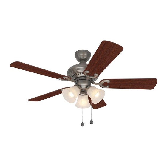
BELLEVUE CEILING FAN
Purchase Date
1
ITEM #0096879
0096950
0096982
0205233
SOS ITEM #0018035
MODEL #E-BE44ABZ5C
E-BE44AN5C
E-BE44MWW5C
E-BE44PPW5C
E-BE44AB5CS
Español p. 22
E124404
Publicidad
Capítulos
Tabla de contenido
Solución de problemas

Manuales relacionados para Harbor Breeze BELLEVUE E-BE44ABZ5C


Resumen de contenidos para Harbor Breeze BELLEVUE E-BE44ABZ5C
- Página 1 ITEM #0096879 0096950 0096982 0205233 SOS ITEM #0018035 Harbor Breeze® is a registered trademark BELLEVUE CEILING FAN of LF, LLC. All Rights Reserved. MODEL #E-BE44ABZ5C E-BE44AN5C E-BE44MWW5C E-BE44PPW5C E-BE44AB5CS Español p. 22 Federal regulations require ceiling fans with light kits manufactured or imported after January 1, 2009, to limit total wattage consumed by the light kit to 190W.
-
Página 2: Tabla De Contenido
TABLE OF CONTENTS Safety Information ........………………………………………………...……..2 - 3 Product Overview ...........................4 Package Contents ..……………………………………………………………..….…....5 Hardware Contents .........................6 Preparation ....….…………………..……………………….…………….………………..6 Initial Installation ....….……………..……………………….……….…..…......7 - 8 Downrod Style Fan Mounting ....................8 - 10 Closemount Style Fan Mounting ....................10 - 11 Wiring .........……………………........…………...12 - 13 Final Installation... -
Página 3: Safety Information
SAFETY INFORMATION WARNINGS To reduce the risk of fire, electrical shock, or personal injury, mount fan to outlet box marked "ACCEPTABLE FOR FAN SUPPORT OF 35 LBS (15.9 KG) OR LESS" and use mounting screws provided with the outlet box. Most outlet boxes commonly used for the support of lighting fixtures are not acceptable for fan support and may need to be replaced. -
Página 4: Product Overview
Congratulations on your purchase of this Harbor Breeze® Ceiling Fan! This product has been specifically designed to give you all the performance you’ll ever need. Harbor Breeze® is the perfect fusion of smart innovation and beautiful style. Designed for more than just air movement, our products are built to function flawlessly... -
Página 5: Package Contents
PACKAGE CONTENTS PART DESCRIPTION QUANTITY PART DESCRIPTION QUANTITY Pull Chain Extension Downrod Socket Ring (preassembled) Canopy Motor Screw Mounting Bracket (preassembled) Motor Housing Lock Washer Yoke Cover (preassembled) Light Kit Fitter Canopy Mounting Screw Blade (preassembled) Blade Arm Pin (preassembled) Glass Shade Clip (preassembled) Candelabra Base Bulb... -
Página 6: Hardware Contents
HARDWARE CONTENTS (shown actual size) Fiber Blade Blade Screw E3 Wire Washer Connector Qty. 15 Qty. 15 Qty. 4 PREPARATION Before beginning assembly of product, make sure all parts are present. Compare parts with package contents list and hardware contents above. If any part is missing or damaged, do not attempt to assemble, the product. -
Página 7: Initial Installation
INITIAL INSTALLATION Turn off circuit breakers and wall switch to the fan supply line leads. (Fig. 1) DANGER: Failure to disconnect power supply prior to installation may result in serious injury or death. Determine mounting method to use. (Fig. 2) A. -
Página 8: Important
INITIAL INSTALLATION Secure mounting bracket (C) to outlet box using screws, spring washers, and flat washers provided with the outlet box. (Fig. 4) *NOTE: It is very important that you use the proper hardware when installing the mounting bracket (C) as this will support the fan. IMPORTANT: If using the angle mount, make sure open end of mounting bracket (C) is installed facing the higher point of the ceiling. - Página 9 DOWNROD STYLE FAN MOUNTING Insert downrod (A) through canopy (B) and yoke cover (E). Thread wires from motor housing (D) through downrod (A). (Fig. 2) Slip downrod (A) into motor housing yoke, align holes and re-install pin (P) and clip (Q). Re-tighten set screws in motor housing yoke and then tighten nuts.
-
Página 10: Closemount Style Fan Mounting
DOWNROD STYLE FAN MOUNTING If you decided to cut back the lead wires in Step 4, strip 1/2 in. of insulation from end of white wire. Twist stripped ends of each strand of wire within the insulation with pliers. (Fig. 5) Repeat Step 5 for black, blue (if applicable) and green wires. - Página 11 CLOSEMOUNT STYLE FAN MOUNTING If necessary, remove every other screw and lock washer from top of motor housing (D). (If there are only three screws and lock washers in top of motor housing (D), the other three screws and lock washers will be located in one of the hardware packs.) (Fig.
-
Página 12: Wiring
WIRING WARNING: To reduce the risk of fire, electrical shock, or personal injury, wire connectors provided with this fan are designed to accept only one 12-gauge house wire and two lead wires from the fan. If your house wire is larger than 12-gauge or there is more than one house wire to connect to the two fan lead wires, consult an electrician for the proper size wire connectors to use. - Página 13 WIRING 1C. FAN AND LIGHT CONTROLLED BY FAN AND LIGHT CONTROLLED BY TWO WALL TWO WALL SWITCHES: If you intend to SWITCHES control the fan and light with separate wall BLACK (WALL SWITCH) switches, connect BLACK wire from fan to BLACK (WALL SWITCH FOR LIGHT) BLACK wire from the independent wall switch 120 V Power...
-
Página 14: Final Installation
FINAL INSTALLATION Temporarily lift canopy (B) to mounting bracket (C) to determine which two canopy mounting screws (O) in mounting bracket (C) align with slotted holes in canopy (B) and partially loosen these two canopy mounting screws (O). Remove the other two canopy mounting screws (O) and star washers (R). - Página 15 FINAL INSTALLATION Remove three fitter plate screws (S) from fitter plate (on underside of motor). Connect male plug Fitter from motor housing (D) to female plug from light Plate kit fitter (F), matching up the colors on the male plug with the colors on the female plug for correct fit.
-
Página 16: Operation Instructions
FINAL INSTALLATION Install three candelabra base 60-watt max. bulbs (J) included. (Fig. 7) Important: When you need to replace bulbs, please allow bulb(s) and light kit to cool down before touching the bulb(s) or the light kit. The pull chain extensions (K) supplied in one of the hardware packs or custom pull chains extensions (sold separately) may be attached to fan and light pull chains. - Página 17 OPERATION INSTRUCTIONS The pull chain labeled LIGHT is used to turn the lights ON or OFF. (Fig. 2) Use the fan reverse switch, located on the switch housing, to optimize your fan for seasonal performance. (Fig. 3) A ceiling fan will allow you to raise your thermostat setting in summer and lower your thermostat setting in winter without feeling a Switch Housing...
-
Página 18: Care And Maintenance
OPERATION INSTRUCTIONS 3C. IMPORTANT: Reverse switch must be set either completely LEFT or completely RIGHT for fan to function. If the reverse switch is set in the middle position (Fig. 3C), fan will not operate. CARE AND MAINTENANCE At least twice each year, lower canopy (B) to check downrod (A) assembly, and then tighten all screws on the fan. -
Página 19: Troubleshooting
TROUBLESHOOTING PROBLEM POSSIBLE CAUSE CORRECTIVE ACTION 1. Tighten all blade screws (AA). Excessive wobbling. 1. Blades (G) are loose. 2. Re-install blade arms (F). 2. Blade arms (H) incorrectly attached. 3. Switch one blade (G) with a 3. Unbalanced blades (G). blade (G) from the opposite side. -
Página 20: Warranty
WARRANTY LIMITED LIFETIME WARRANTY: Litex Industries warrants this fan to be free from defects in workmanship and materials present at time of shipment from the factory for Lifetime limited from the date of purchase. This warranty applies only to the original purchaser. Litex Industries agrees to correct any defect at no charge or, at our option, replace the ceiling fan with a comparable or superior model. -
Página 21: Replacement Parts List
REPLACEMENT PARTS LIST For replacement parts, call our customer service department at 1-800-527-1292, 8:30 a.m. - 5:00 p.m., CST, Monday - Friday. When ordering parts, please have the Model # or Item # of the fan available, which can be found on page 1. PART DESCRIPTION Downrod... -
Página 22: Adjunte Su Recibo Aquí
ARTÍCULO #0096879 0096950 0096982 0205233 ARTÍCULO SOS #0018035 ® Harbor Breeze es una marca registrada VENTILADOR DE de LF, LLC. Todos los derechos reservados. TECHO BELLEVUE MODELO #E-BE44ABZ5C E-BE44AN5C E-BE44MWW5C E-BE44PPW5C E-BE44AB5CS Los reglamentos federales requieren que los ventiladores de techo con kit de iluminación fabricados o importados después del 1 de enero de 2009, tengan un límite... - Página 23 ÍNDICE Información de seguridad ........………………………………………..23 - 24 Descripción general del producto ....................25 Contenido del paquete ..…………………………………………………………………………..…..26 Aditamentos ..........................27 Preparación ....….…………………..……………………….…………………………………..27 Instalación inicial ....….……………..……………………….……….…..…......28 - 29 Estilo de montaje de varilla del ventilador ................29 - 30 Estilo de montaje cerrado del ventilador ................31 - 32 Cableado .........……………………..............33 - 34...
-
Página 24: Información De Seguridad
INFORMACIÓN DE SEGURIDAD ADVERTENCIAS Para reducir el riesgo de incendios, descargas eléctricas o lesiones personales, monte a una caja de salida marcada como "ACCEPTABLE FOR FAN SUPPORT OF 35 LBS (15.9 KG) OR LESS" (apta para sostener un ventilador de 15,88 kg (35 lb) o menos) y utilice los tornillos de montaje incluidos en la caja de salida. -
Página 25: Descripción General Del Producto
DESCRIPCIÓN GENERAL DEL PRODUCTO Felicitaciones por la compra de este ventilador de techo Harbor Breeze ® . Este producto ha sido específicamente diseñado para brindarle todo el rendimiento que necesita. ® Harbor Breeze es la fusión perfecta de la innovación inteligente y la belleza en el estilo. -
Página 26: Contenido Del Paquete
CONTENIDO DEL PAQUETE PIEZA DESCRIPCIÓN CANTIDAD PIEZA DESCRIPCIÓN CANTIDAD Extensión para la cadena de tiro Varilla Anillo del portalámpara (preensamblado) Base Tornillo del motor (preensamblado) Abrazadera de montaje Arandela de seguridad Carcasa del motor (preensamblada) Cubierta de la horquilla Tornillo de montaje de la base Soporte del kit de iluminación (preensamblado) Aspa... -
Página 27: Aditamentos
ADITAMENTOS (se muestran en tamaño real) Arandela Tornillo para aspa para aspa Conector de fibra cables E3 Cant. 15 Cant. 15 Cant. 4 PREPARACIÓN Antes de comenzar a ensamblar el producto, asegúrese de tener todas las piezas. Compare las piezas con la lista del contenido del paquete y la lista de aditamentos anteriores. No intente ensamblar el producto si falta alguna pieza o si éstas están dañadas. -
Página 28: Instalación Inicial
INSTALACIÓN INICIAL Interrumpa el suministro de energía del ventilador apagando los interruptores de circuito y el interruptor de pared. (Fig. 1) PELIGRO: Si no interrumpe el suministro de electricidad antes de la instalación, pueden producirse lesiones graves o la muerte. Determine el método de instalación que utilizará. -
Página 29: Importante
INSTALACIÓN INICIAL Asegure la abrazadera de montaje (C) a la caja de salida con los tornillos, las arandelas de resorte y las arandelas planas que incluye la caja de salida. (Fig. 4) *NOTA: Es muy importante que use los aditamentos adecuados para instalar la abrazadera de montaje (C), ya que ésta soportará... - Página 30 ESTILO DE MONTAJE DE VARILLA DEL VENTILADOR Introduzca la varilla (A) a través de la base (B) y la cubierta de la horquilla (E). Pase los conductores desde la carcasa del motor (D) a través de la varilla (A). (Fig. 2) Deslice la varilla (A) en la horquilla de la carcasa del motor, alinee los orificios y vuelva a instalar el pasador (P) y el sujetador (Q).
-
Página 31: Estilo De Montaje Cerrado Del Ventilador
ESTILO DE MONTAJE DE VARILLA DEL VENTILADOR Si decidió cortar los cables conductores en el Paso 4, pele 1,27 cm del aislamiento del extremo del conductor blanco. Tuerza los extremos pelados de cada filamento de conductor dentro del aislamiento con pinzas. (Fig. - Página 32 ESTILO DE MONTAJE CERRADO DEL VENTILADOR Si es necesario, retire todos los otros tornillos y las arandelas de seguridad de la parte superior de la carcasa del motor (D). (Si sólo hay tres tornillos y arandelas de seguridad en la parte superior de la carcasa del motor (D), los otros tres tornillos y arandelas de seguridad estarán ubicados en uno de los paquetes de aditamentos).
-
Página 33: Cableado
CABLEADO ADVERTENCIA: Para reducir el riesgo de incendios, descargas eléctricas o lesiones personales, los conectores de cables incluidos con este ventilador están diseñados para soportar sólo un cable interior de calibre 12 y dos cables conductores del ventilador. Si el cable interior es de un calibre superior a 12 o hay más de un cable interior para conectar los dos cables conductores del ventilador, pregúntele a un electricista cuál es el tamaño adecuado de los conectores de... -
Página 34: Ventilador Y Luz Controlados Por Dos Interruptores De Pared: Si
CABLEADO 1C. VENTILADOR Y LUZ CONTROLADOS VENTILADOR Y LUZ CONTROLADOS POR DOS POR DOS INTERRUPTORES DE PARED: Si INTERRUPTORES DE PARED desea controlar el ventilador y la luz con NEGRO (INTERRUPTOR DE PARED) interruptores de pared separados, conecte el NEGRO (INTERRUPTOR DE PARED PARA LA LUZ) conductor NEGRO del ventilador al conductor Alimentación NEGRO del interruptor de pared independiente... -
Página 35: Instalación Final
INSTALACIÓN FINAL Levante temporalmente la base (B) hacia la abrazadera de montaje (C) para determinar cuáles son los dos tornillos de montaje de la base (O) en la abrazadera de montaje (C) que se alinean con los orificios ranurados en la base (B) y afloje parcialmente estos dos tornillos de montaje de la base (O). - Página 36 INSTALACIÓN FINAL Retire tres tornillos de la placa de soporte (S) de Placa la placa de soporte (en la parte inferior del motor). Conecte el enchufe macho de la carcasa del soporte motor (D) al enchufe hembra del soporte del kit de iluminación (F), haciendo combinar los colores del enchufe macho con los del enchufe hembra Conector...
-
Página 37: Instrucciones De Funcionamiento
INSTALACIÓN FINAL Instale las tres bombillas de base candelabro de 60 vatios como máximo (J) incluidas. (Fig. 7) Importante: Cuando necesite reemplazar las bombillas, deje que pase un tiempo para que la(s) bombilla(s) y el kit de iluminación se enfríen antes de tocar la(s) bombilla(s) o el kit de iluminación. - Página 38 INSTRUCCIONES DE FUNCIONAMIENTO La cadena de tiro marcada como “LIGHT” (LUZ) se utiliza para ENCENDER o APAGAR las luces. (Fig. 2) Utilice el interruptor de reversa del ventilador, ubicado en la carcasa del interruptor, para optimizar el rendimiento de su ventilador según la estación del año.
-
Página 39: Cuidado Y Mantenimiento
INSTRUCCIONES DE FUNCIONAMIENTO 3C. IMPORTANTE: El interruptor de reversa se debe configurar ya sea completamente HACIA LA IZQUIERDA o completamente HACIA LA DERECHA para que funcione el ventilador. Si el interruptor de reversa se configura en la posición del medio (Fig. 3C), el ventilador no funcionará. CUIDADO Y MANTENIMIENTO Al menos dos veces al año, baje la base (B) para revisar en ensamble de la varilla (A) y luego apriete todos los tornillos en el ventilador. - Página 40 SOLUCIÓN DE PROBLEMAS PROBLEMA CAUSA POSIBLE ACCIÓN CORRECTIVA El funcionamiento 4. El ventilador es nuevo. 4. Permita que el ventilador tenga es ruidoso. un período de asentamiento de un par de días, especialmente al encender el ventilador a velocidades media y alta. 1.
-
Página 41: Garantía Limitada De Por Vida
GARANTÍA GARANTÍA LIMITADA DE POR VIDA: Litex Industries garantiza que este ventilador no presenta defectos de fabricación ni en los materiales presentes en el momento del transporte desde la fábrica durante un período limitado de por vida a partir de la fecha de compra. Esta garantía es válida sólo para el comprador original. -
Página 42: Lista De Piezas De Repuesto
LISTA DE PIEZAS DE REPUESTO Para obtener piezas de repuesto, llame a nuestro Departamento de Servicio al Cliente al 1-800-527-1292, de lunes a viernes de 8:30 a.m. a 5:00 p.m., hora central estándar. Cuando pida piezas, tenga a mano el # de modelo o # de artículo del ventilador, los que aparecen en la página 22. PIEZA DESCRIPCIÓN Varilla...