Tabla de contenido
Publicidad
Idiomas disponibles
Idiomas disponibles
Enlaces rápidos
Harbor Breeze® is a registered trademark of LF, LLC.
All Rights Reserved.
Federal regulations require ceiling fans with light kits manufactured or imported after
January 1, 2009, to limit total wattage consumed by the light kit to 190W. Therefore,
this fan is equipped with a wattage limiting device.
WARNINGS
• READ AND SAVE THESE INSTRUCTIONS.
• Read this manual carefully and completely before attempting to assemble, install or operate this product.
• Be sure you read and understand the Safety Precautions on page 3 of these instructions.
• Do not discard fan carton or foam inserts. Should this fan need to be returned to the factory for repairs, it must be
shipped in its original packaging to ensure proper protection against damage that might exceed the initial cause for
return.
•
CAUTION: Before proceeding, be sure to shut off electricity at main switch or circuit breaker in order to avoid
electrical shock.
•
WARNING: To reduce the risk of fire or electric shock, do not use the fan with any solid state speed
control device or control fan speed with a full range dimmer switch.
•
WARNING: To reduce the risk of fire, electric shock, or personal injury, do not bend the blade arms when
installing them, balancing the blades, or cleaning the fan. Do not insert foreign objects between the rotating fan
blades. Mount to outlet box marked "ACCEPTABLE FOR FAN SUPPORT" and use mounting screws provided with
the outlet box. Most outlet boxes commonly used for the support of lighting fixtures are not acceptable for fan
support and may need to be replaced. Consult a qualified electrician if in doubt.
Questions, problems, missing parts? Before returning to your retailer, call or contact our customer service
department at 1-800-527-1292, 8:30 a.m.-5:00 p.m., CST, Monday-Friday.
SOS ITEM/ARTICULO SOS #0125086
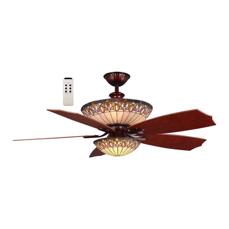
MONTCLAIR/CEILING FAN
MONTCLAIR/VENTILADOR DE TECHO
MODEL/MODELO #E-CM54RBZ5CRCI
(página 13)
E192641
Publicidad
Capítulos
Tabla de contenido

Manuales relacionados para Harbor Breeze E-CM54RBZ5CRCI


Resumen de contenidos para Harbor Breeze E-CM54RBZ5CRCI
- Página 1 MONTCLAIR/VENTILADOR DE TECHO (página 13) MODEL/MODELO #E-CM54RBZ5CRCI Harbor Breeze® is a registered trademark of LF, LLC. All Rights Reserved. Federal regulations require ceiling fans with light kits manufactured or imported after January 1, 2009, to limit total wattage consumed by the light kit to 190W. Therefore, this fan is equipped with a wattage limiting device.
-
Página 2: Tabla De Contenido
TABLE OF CONTENTS Safety Information ......…………………………………………………………………….……...……..….3 Package Contents ......…………………………………………………………………………...……..4 Preparation .........….…………………..……………………….…………….………………..5 Initial Installation .........…………………………………………………...…………...…..5 Fan Mounting ......………......………………………………….………………………...….6 Wiring for Remote Control and Fan .............………………………………..6 - 7 Final Installation ....………………….…………….……………………….…………….……....…….7 - 8 Automated Learning Process/Activating Code ............……………………………………..…..9 Remote Control and Fan Operation .......................9 - 10 Lighted Housing Bulb Replacement ........................10... -
Página 3: Safety Information
SAFETY INFORMATION READ AND SAVE THESE INSTRUCTIONS Please read and understand this entire manual before attempting to assemble, install or operate the product. If you have any questions regarding the product, please call customer service at 1-800-527-1292, 8:30 a.m.-5:00 p.m., CST, Monday-Friday. -
Página 4: Package Contents
PACKAGE CONTENTS Part Description Quantity Downrod Canopy Mounting Bracket Yoke Cover Motor Housing Shade Fitter Light Kit Fitter Glass Shade Blade Arm Blade Motor Screw (in motor) 3/16 Blade Screw (in hardware pack) 5/32 Lock Washer (in hardware pack) 5.4M/M Lock Washer (in motor and hardware pack) Blade Washer (in hardware pack) 4M Washer (in hardware pack) -
Página 5: Preparation
PREPARATION 1. Before beginning assembly and installation of product, make sure all parts are present. Compare parts with "Package Contents" list and diagrams on the previous page. If any part is missing or damaged, do not attempt to assemble, install or operate the product. Contact customer service for replacement parts as indicated at the bottom of page 4. -
Página 6: Fan Mounting
FAN MOUNTING 1. Remove pin (T) and clip (U) from motor housing yoke at top of motor housing (E) and partially loosen set screws. [Fig. 1] Screw *Helpful Hint: Downrod style mounting is best suited for ceilings 8 ft. high or higher. For taller ceilings you may want to use a longer downrod (not included) than the ones supplied. -
Página 7: Final Installation
WIRING FOR REMOTE CONTROL AND FAN (continued from previous page) ground 1. Make the necessary wiring connections for remote operation white supply wire (green or bare) according to Fig. 1. For each wire connection, use one of the black supply wire wire connectors (Q) provided, making sure to screw wire connector (Q) on in a clockwise direction. - Página 8 FINAL INSTALLATION (continued from previous page) 2. Position blade arm (I) under blade (J) and secure blade arm (I) with screws (L) and washers (O). Do not tighten screws (L) until each screw (L) has been started. Then, tighten each screw (L) starting with the center screw (L).
-
Página 9: Automated Learning Process/Activating Code
AUTOMATED LEARNING PROCESS/ACTIVATING CODE CAUTION: The remote control transmitter (W) can be programmed to multiple receivers or fans. If this is not desired, turn wall switch off to any other programmable receiver or fan. Code Switches 1. Remove battery cover from back side of remote control transmitter (W). -
Página 10: Lighted Housing Bulb Replacement
REMOTE CONTROL AND FAN OPERATION (continued from previous page) 2. Use the fan reverse switch, located on top of the motor housing (E), to optimize your fan for seasonal performance. [Fig. 2] A ceiling fan will allow you to raise your thermostat setting in summer and lower your thermostat setting in winter without feeling a difference in your comfort. -
Página 11: Troubleshooting
TROUBLESHOOTING WARNING: Before beginning work, shut off the power supply to avoid electrical shock. Problem Possible Cause Corrective Action Fan does not move. 1. Reverse switch not engaged. 1. Push switch firmly either right or left. 2. Power is off or fuse is blown. 2. -
Página 12: Warranty
WARRANTY LIMITED LIFETIME WARRANTY: Litex Industries warrants this fan to be free from defects in workmanship and materials present at time of shipment from the factory for Lifetime limited from the date of purchase. This warranty applies only to the original purchaser. Litex Industries agrees to correct any defect at no charge or, at our option, replace the ceiling fan with a comparable or superior model. -
Página 13: Montclair/Ventilador De Techo
ARTICULO SOS #0125086 MONTCLAIR/VENTILADOR DE TECHO MODELO #E-CM54RBZ5CRCI MODELO #E-CM Harbor Breeze® es marca registrada de es marca registrada de es marca registrada de LF, LLC. Reservados todos los derechos. dos todos los derechos. El reglamento federal requiere que un ventilador de techo con juego de luz fabricado o importado después del 1... - Página 14 INDICE DE MATERIAS Información de seguridad ....………………………………………………………………………...……..… 15 Contenido del paquete ......…………………………………………………………………………..……. 16 Preparación ..........….…………………..……………………….…………….………………. 17 Instalación inicial ..........………………………………………………..…....17 - 18 Montaje del ventilador ........……………………………………………………......… 18 Conexión de los cables del control remoto y el ventilador .........……........19 Instalación final .…………………….....................… 20 - 21 Proceso de aprendizaje automático/Activando el código ……………............…..21 Funcionamiento del control remoto y el ventilador...
-
Página 15: Información De Seguridad
INFORMACION DE SEGURIDAD POR FAVOR LEA Y GUARDE ESTAS INSTRUCCIONES Por favor lea el instructivo entero antes de tratar de ensamblar, instalar o hacer funcionar el producto. Si tiene alguna pregunta acerca del producto, por favor llame al servicio al cliente al 1-800-527-1292, de 8:30 a.m. a 5:00 p.m., hora central, de lunes a viernes. -
Página 16: Contenido Del Paquete
CONTENIDO DEL PAQUETE Pieza Descripción Cantidad Vástago Cubierta Soporte de montaje Cubierta del yugo Bastidor del motor Conectador para la pantalla Conectador para el juego de luz Pantalla de vidrio Brazo para la paleta Paleta Tornillo del motor (en el motor) Tornillo para la paleta 4,76 mm (en paquete de artículos de ferretería) Arandela de seguridad 5/32... -
Página 17: Preparación
PREPARACION 1. Antes de empezar con el ensamblaje e instalación del producto, asegúrese de tener todas las piezas. Compare las piezas con la lista y los diagramas del "Contenido del paquete" en la página anterior. Si falta alguna pieza o se encuentra dañada, no trate de ensamblar, instalar o hacer funcionar el producto. -
Página 18: Montaje Del Ventilador
INSTALACION INICIAL (continúa de la página anterior) 5. Saque los tornillos de montaje para los brazos para las paletas (K) y las arandelas de seguridad (N) del lado inferior del motor. Quite la placa de estabilización del motor de color azul y deséchela. [Fig. 5] placa de estabilización Fig. -
Página 19: Conexión De Los Cables Del Control Remoto Y El Ventilador
CONEXION DE LOS CABLES DEL CONTROL REMOTO Y EL VENTILADOR ADVERTENCIA: Para reducir el riesgo de incendio, choque eléctrico o daño corporal, los conectores para cable provistos con este ventilador son diseñados para aceptar sólo un cable de calibre 12 de la casa y dos cables principales del ventilador. -
Página 20: Instalación Final
INSTALACION FINAL (continúa en la página siguiente) 1. Localice los dos tornillos para montaje de la cubierta (S) en la parte inferior del soporte de montaje (C) y quite el tornillo (S) que está localizado más cerca del extremo abierto del soporte de montaje (C). Afloje parcialmente el otro tornillo (S). -
Página 21: Proceso De Aprendizaje Automático/Activando El Código
INSTALACION FINAL (continúa de la página anterior) 8. Quite un tornillo de por dentro de la pantalla de vidrio (H) y afloje parcialmente los otros tres tornillos. Alinee los tres tornillos aflojados en la pantalla de vidrio (H) con los agujeros con ranura en el conectador para la pantalla (F). -
Página 22: Funcionamiento Del Control Remoto Y El Ventilador
FUNCIONAMIENTO DEL CONTROL REMOTO Y EL VENTILADOR 1. Botones de funcionamiento en el panel del transmisor del control remoto (W) [Fig. 1] : Botón HI para velocidad ALTA del ventilador Botón MED para velocidad MEDIA del ventilador Botón LOW para velocidad BAJA del ventilador Botón FAN/OFF para APAGAR el ventilador Botón TOP LIGHT... -
Página 23: Cuidado Y Mantenimiento
CUIDADO Y MANTENIMIENTO Baje Ia cubierta (B) para inspeccionar el conjunto del vástago (A) por lo menos dos veces al año, y luego apriete todos los tornillos del ventilador. Limpie el bastidor del ventilador (E) solamente con un cepillo suave o un paño que no tenga pelusa para no rayar el acabado. -
Página 24: Garantía
LOCALIZACION DE FALLAS (continúa de la página anterior) Problema Causa posible Acción correctiva El ventilador funciona pero 3. El interruptor de pared para el 3. Asegúrese de que el interruptor de las luces no. (cont.) ventilador está apagado. pared para el ventilador esté prendido. 4.