Cepex PVC-U Manual De Instalación Y Mantenimiento
Válvula de bola extreme
Ocultar thumbs
Ver también para PVC-U:
- Manual del usuario (53 páginas) ,
- Manual de instalación y mantenimiento (53 páginas) ,
- Manual de instrucciones (15 páginas)
Publicidad
Idiomas disponibles
Idiomas disponibles
Enlaces rápidos
ENGLISH
EXTREME BALL VALVE
EXTREME BALL VALVE
INSTALLATION AND
Declaración de conformidad CE
MAINTENANCE
El fabricante / the
MANUAL
Declara que nuevas vávulas / declares that our
Tipo / Type: Válvulas de Bola Manuales / Manual Ball valves
Modelos / Models: [IND] and EXTREME SERIES
Material del cuerpo / Body material:
Cumplen con los requisitos establecidos por la Unión Europea para EQUIPOS A PRESIÓN según
Directiva 97/23/CE (PED), categoria I modulo A, de acuerdo con las normas harmonizadas:
- EN ISO 16135 VÁLVULAS INDUSTRIALES: Válvulas de bola de materiales termoplásticos.
Meets the requirements established by the European Union for PRESSURE EQUIPMENT according to
Directive 97/23/EC (PED), category I module A, in accordance with the harmonized standards:
- EN ISO 16135 INDUSTRIAL VALVES: Ball valves of thermoplastic materials.
La marca CE sobre la válvula hace referencia a esta conformidad. Según la directiva 97/23/CE
solamente las válvulas mayores a DN25 pueden ir marcadas con CE.
The CE marking on the valve refers to this conformity. According to Directive 97/23/EC only valves
larger than DN25 can be marked with CE.
1. DEFINITION
Ball valve for isolating the flow in liquid handling systems.
Design based on the EN ISO 16135:2007 Standard in accordance with the 97/23/EC Directive.
The valve is available with PVC-U, CPVC, PPH, PVDF and ABS bodies and EPDM and FPM (FKM) sealing gaskets. The choice of material
for the body and gaskets depends on the type of liquid to be carried and on the working temperature of the liquid, in accordance with
the chemical resistance tables available on our website and the pressure/temperature chart in this Manual.
2. GENERAL ADVICES
•
The valves described in this manual are especially designed to ensure a correct flow circulation in all working phases.
•
Apparatus should be installed in accordance with the specific instructions for each installation. All existing safety legislation
should be respected at all times in order to avoid accidents.
•
Any modification to the ball valve requires the prior authorisation of the manufacturer. Spare parts and accessories authorised by
the manufacturer are a guarantee of greater safety. The manufacturer of this valve is exempt from all responsibility for damage
arising from unauthorised spare parts and accessories.
•
The user should ensure that all assembly and maintenance work is carried out by suitably authorised, qualified personnel, and that
these have previously read the installation and service instructions set out in this manual.
•
Avoid shocks during transport, since they may damage the body of the valve.
•
Store the valve in the original packaging, protected against humidity and direct sunlight.
The maximum service life of the valve is specified in EN ISO 16135:2007. It is verified on the production plant by aging tests
•
specified in the standard.
•
Correct installation and handling of the valve, as well as adherence to the maximum pressure and temperature conditions speci-
fied in this manual are essential for preserving the service life of the valve.
•
The driven liquid must be compatible with the valve materials. Consult chemical resistance charts published by Cepex or consult
the technical department.
•
Using tools for opening or closing the manual valve control is not recommended.
•
Before carrying out any maintenance operations on the pipe or valve, ensure that the system is depressurised by releasing the
pressure and emptying the pipes, following the specific safety regulations of each product.
•
Before installation, check that the valve is undamaged and that it contains all the parts required for installation.
•
It is important to avoid rapid closure of valves to eliminate the possibility of water hammer causing damage to the pipeline.
•
When using the valve as the final element of a installation, take into account the risks of the liquid and control the pressure and
temperature, according to the standards of safety of each product.
•
It is not recommended to use this valve for transport of solids or liquids with impurities that may damage the seat or the ball of
the valve.
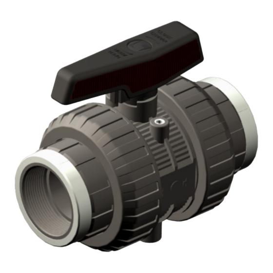
3. COMPONENTS
Fig. 1
15
14
13
5
16
10
2
11
7
8
4
3
4. BALL VALVE TECHNICAL SPECIFICATIONS
DN10-DN50 (PVC-U, CPVC, PVDF): PN16 at 20ºC liquid temperature.
DN65-DN80 (PVC-U, CPVC, PVDF): PN10 at 20ºC liquid temperature.
DN65-DN80 (PPH): PN6 at 20ºC liquid temperature.
DN10-DN50 (PPH, ABS): PN10 at 20ºC liquid temperature.
The working pressure of the valve reduces with increasing liquid temperature, as shown in the accompanying chart.
Pressure / Temperature Chart.
DN15 - DN50 (PVC-U, CPVC, PPH)
(G 4.1)
psi bar
PVC-U
PVC-C
PP-H
0
10
20
30
40
50
60
70
80
90
100
32
50
68
86
104
122
140
158
176
194
212
DN65 - DN80 (PVC-U, CPVC, PVDF)
(G 4.3)
psi bar
PVC-U
PVC-C
ºC
0
10
20
30
40
50
60
70
80
90
100
ºF
32
50
68
86
104
122
140
158
176
194
212
Valve operating torque
Operating torque table (N·m)
Operating torque values at rated pressure (PN)
and 20 °C in as new direct from the factory
condition. Installation and operating condi-
N·m
tions (pressure and temperature) will affect
lbf·inch
these values.
The actuator that is required for an automatic
operation must be calculated according to
some safety factors that were determined in
life tests carried out in the factory.
PVC-U
(PTFE - EPDM/FPM)
CPVC
(PTFE - EPDM/FPM)
PPH
(PTFE - EPDM/FPM)
PVDF
(PTFE - EPDM/FPM)
ABS
(PTFE - EPDM/FPM)
/ EC Declaration of Conformity
manufacturer:
CEPEX S.A.U.
Avinguda Ramon Ciurans 40 ( Parcel.la 6) - P. I. Congost - 08530 LA GARRIGA
valves:
PVC-U, PVC-C, PPH, PVDF, ABS.
La Garriga, April 2015
T 3.1
N
DESCRIPTION
MATERIAL
1
Body
PVC-U, PPH, CPVC, PVDF, ABS
2
Shaft
PVC-U, PPH, CPVC, PVDF, ABS
3
Ball
PVC-U, PPH, CPVC, PVDF, ABS
4
Seal carrier
PVC-U, PPH, CPVC, PVDF, ABS
5
Nut
PVC-U, PP, CPVC, PVDF, ABS
6
End connector
PVC-U, PPH, CPVC, PVDF, ABS, PE-100
*Threaded versions with stainless
steel ring AISI-304
7
Ball Seat
PTFE
8
O-ring
EPDM / FPM
9
O-ring
EPDM / FPM
6
10
O-ring
EPDM / FPM
9
1
11
Dampener seal
EPDM / FPM
12
Insert
Stainless steel AISI-303
13
Handle
PP-GR
12
14
Screw
Stainless steel A4-70
15
Cap
PP
16
Adjusting tool
ABS
DN15 - DN50 (PVDF, ABS)
psi bar
-30
-20
-10
0
10
20
30
40
50
60
-22
-4
14
32
50
68
86
104
122
140
ºC
ºF
DN65 - DN80 (PPH, PVDF)
-30
-20
-10
0
10
20
30
40
50
60
70
-22
-4
14
32
50
68
86
104
122
140
158
(T4.1)
DN15
DN20
DN25
DN32
DN40
DN50
1
2
3,5
3,5
5
15
17,7
31
31
8,9
44,3
132,8
ENGLISH
Pressure loss table (T4.2)
DN
D
10
16
15
20
20
25
25
32
32
40
40
50
50
63
65
75
75
90
Valve connections
Threads: ISO 7-1, ISO 228-1
Flanges: EN 558-1, EN 1092-1
PVC-U, CPVC, ABS: ISO 15493
PPH, PE-100: ISO 15494
PVDF: ISO 10931
5. DIMENSIONS
T 5.1(mm)
Yasmin Fernádez
Fig. 4
Quality management
K
6. INSTALLATION AND COMMISSIONING
Before commencing the installation process, check that you have all the parts needed for the valve assembly, and that the materials,
connection type and nominal pressure are suitable for the installation.
For solvent or welded connections, ensure also that the parts to be connected are of the same material and that you are using the correct
solvent or welding tools.
To install the valve, follow best installation practice recommendations provided on the Cepex website, paying particular attention to
thermal expansion and pipe alignment.
When filling the pipes with liquid, check that all the air is purged from the system and that the initial pressure does not exceed the nominal
pressure of the valve, or of the system element with the lowest nominal pressure rating.
Install the valve pointing in the direction of flow marked on the body of the valve (downstream).
Install the valve once the sockets are solvent-bonded and dry, to avoid problems with the adhesive (entry of the latter into the valve).
The valve is supplied assembled from the factory and the following steps should be followed for its installation:
1. Check that the diameter of the tube corresponds to the inside of the end connector (if it is a solvent socket).
2. Adjust the valve to the installation leaving the union nut (3) Fig. 6 on the tube before gluing the end connector (5) Fig. 7.
3. Leave an exact distance between end connectors (see Fig. 8), so that the body of the valve can be easily introduced, preventing it from
Q
being strained by both ends of the tubing.
4. Solvent sockets (PVC-U / PVC-C / ABS) are made by cleaning the areas to be joined with a suitable solvent and then adding adhesive. It
1
not recommended that pressure is applied until 24 hours after gluing.
In the solvent operation you have to separate the body of the end connectors, just to avoid the adhesive damages the valve internal parts.
1
5. PTFE tape is placed in the male threads of the threaded unions: "it is very important that an excessive amount is not used as when it is
1
put together it could cause breakage of the female housing".
6. The soldered unions (PE / PP-H / PVDF) are made taking into account the instructions of the soldering tool used.
1
This range of valves allows the valve to be fixed to a base using threaded inserts at the bottom.
2
When using the inserts, take note of the dimensions of the screws.
2
3
Fig. 6
2
2
2
1
7. OPERATION AND MAINTENANCE INSTRUCTIONS
2
If the valve is installed correctly pointing in the direction of flow marked on the body, it is possible to carry out the maintenance downs-
4
tream without problems. By simply closing the valve this acts as a plug. If on the contrary it is upstream where maintenance is required, it
1
is essential that there is no pressure in the circuit when dismantling the union nut and end connector.
The operations described next are always carried out without fluid in the line.
1
The valve is adjusted in the factory for correct and prolonged functioning. Nevertheless, it is possible to readjust the tightening of the
sealing gasket on the ball when the conditions of use so require it.
1
This operation is carried out with the help of the handle or the supplied tool (Fig. 18).
1
Dismantle the valve's union nuts (3) and remove them from their housing. Put the outil into the slot that is found in the seal carriers for
this purpose (12) and turn the key anti-clockwise to tighten the o-ring and clockwise to loosen it. If any of the components of the valve
wear out, you can replace them by dismantling the body of the valve. To do so, proceed in the same way with the adjustment but turn it
clockwise until the seal carriers (12) are free. When you have done this you may substitute any of the body's O-rings. Turn the shaft until the
ball is in a closed position; remove the ball (2) and remove the ball seat (9).
To replace the shaft, it has to be forced as shown in Fig.16. Once the shaft has been removed (1) the o-rings can be replaced (7). Remember
that excessive force on the seal carriers can affect the action which can damage the actual functioning of the valve.
Assembly can be done by reversing the process but always taking the precaution of lubricating the o-rings with PTFE oil. Do not use grea-
se or mineral oils that attack the material of the o-rings.
12
Fig. 12
(G 4.2)
PVDF
ABS
ºC
70
80
90
100
110
120
ºF
158
176
194
212
230
248
(G 4.4)
PVDF
PPH
8. TROUBLESHOOTING
FAULT
Leackage on the body of the valve
80
90
100
110
120
176
194
212
230
248
Leackage on the shaft of the valve
DN65
DN80
The torque is too strong or the valve
is blocked
25
45
221,3
398,3
EXTREME BALL VALVE
Pressure loss chart (G 4.4)
Kv (l/min)
Cv (GPM)
75
5,3
190
13,3
380
26,6
690
48,3
980
68,6
1600
112
3000
210,1
5500
385,2
6800
476,2
Actuator coupling
(Optional)
EN/ISO 5211
Flow / Débit / Caudal / Portata / Durchfluss / Caudal
DN
D / G
A ± 2 (PVC-U,
A' ± 2
B
B
CPVC, ABS)
PPH, PVDF
cemented
welded
threaded
10
16 - 3/8"
102
101
15,5
14,5
15
20 - 1/2"
102
101
17
15,5
20
25 - 3/4"
120
118
20
17
25
32 - 1"
139
136
23
19
32
40 - 1 1/4"
156
151
27,5
21,5
40
50 - 1 1/2"
170
165
32
24,5
50
63 - 2"
197
190
39,5
28,5
65
75 - 2 1/2"
238
-
45
-
80
90 - 3"
278
-
53
-
Fig. 7
8
6 9
10
Fig. 13
Fig. 18
T 8.1
POSSIBLE CAUSE
Wear of the body o'ring
Looseness of the seal carrier
Presence of solids or strange elements
Wear of the shaft o'rings
The seal carrier is over-tight
CODE: C560073XT - Version 2: 2017/03
COPYRIGHT © CEPEX, S.A.U. - ALL RIGHTS RESERVED
B
C
E
J
K
L
R ± 2
F
H
± 2
8,5
26
53
16
M4
48
-
-
-
13,5
26
53
16
M4
48
170,5
65
130
15,5
31,5
65
20
M5
56
75
150
18,5
36
73
24
M5
66
204,5
85
160
20
45
88
28
M5
74
226
100
180
20
51
102
30
M8
77
250
110
195
24
61
114
37,5
M8
90
296
125
223
27
75
137
38
M8
117
-
145
290
30
88,5
153
53
M8
140
-
160
310
Fig. 8
5
Fig. 14
Fig. 15
9
2
Fig. 16
7
1
Fig. 17
FAULT CLEARANCE
Change the o'ring
Ajust the seal carrier
Remove the valve and replace damaged parts
Change the o'rings
Ajust the seal carrier
E
-
95
105
140
150
165
185
200
220
Publicidad

Manuales relacionados para Cepex PVC-U


Resumen de contenidos para Cepex PVC-U
- Página 1 The CE marking on the valve refers to this conformity. According to Directive 97/23/EC only valves 5. DIMENSIONS larger than DN25 can be marked with CE. D / G A ± 2 (PVC-U, A’ ± 2 R ± 2 CPVC, ABS)
- Página 2 The CE marking on the valve refers to this conformity. According to Directive 97/23/EC only valves 5. DIMENSIONES D / G A ± 2 (PVC-U, A’ ± 2 R ± 2 larger than DN25 can be marked with CE.