Tabla de contenido
Publicidad
Idiomas disponibles
Idiomas disponibles
Enlaces rápidos
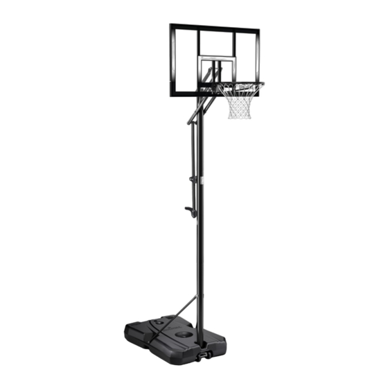
PORTABLE BASKETBALL SYSTEM
Toll-Free Customer Service Number
U.S.:
1-800-558-5234
Canada:
1-800-284-8339
Europe:
+353 51 379777
Australia: 1300 367 582
www.spalding.com
WARNING
READ AND UNDERSTAND THE OPERATOR'S
MANUAL BEFORE USING THIS UNIT.
FAILURE TO FOLLOW THE OPERATING
INSTRUCTIONS COULD RESULT IN INJURY
OR DAMAGE TO PROPERTY.
Owner's Manual
Model Number:
(found on product box)
10/21 ID# M7A1021
ENGLISH
Publicidad
Capítulos
Tabla de contenido

Manuales relacionados para SPALDING M7A1021


Resumen de contenidos para SPALDING M7A1021
- Página 1 1-800-558-5234 Canada: 1-800-284-8339 Europe: +353 51 379777 Australia: 1300 367 582 www.spalding.com WARNING READ AND UNDERSTAND THE OPERATOR’S MANUAL BEFORE USING THIS UNIT. FAILURE TO FOLLOW THE OPERATING INSTRUCTIONS COULD RESULT IN INJURY OR DAMAGE TO PROPERTY. 10/21 ID# M7A1021...
-
Página 2: Tabla De Contenido
FAILURE TO FOLLOW OPERATING INSTRUCTIONS COULD RESULT IN INJURY OR DAMAGE TO PROPERTY. Contact Questions or missing parts? Do NOT go back to the store! warrantyservice@custserv.fotlinc.com Email: Customer Service 1-800-558-5234 Toll-Free Number: Mailing Address: Spalding PO Box 90015 Bowling Green, KY 42102... -
Página 3: Warranty
Warranty Warranty For the very latest Basketball System Warranty information, please visit www.Spalding.com or call Spalding Customer Service at 1-800-558-5234. Safety Information WARNING FAILURE TO FOLLOW THESE SAFETY INSTRUCTIONS MAY RESULT IN SERIOUS INJURY OR PROPERTY DAMAGE AND WILL VOID THE WARRANTY. -
Página 4: Test-Fit Close Tolerance Bolts
Test-Fit Close Tolerance Bolts Test-Fit Close Tolerance Bolts To ensure optimal playability of the backboard system, a close tolerance fit between the elevator components and hardware is required. Test-fit large bolts into large holes of elevator tubes, backboard brackets, and triangle plates. Carefully rock them in a circular motion to remove any excess paint from holes if necessary. - Página 5 Package Contents KIT 1 – 209157 203099Hex Locknut (Nylon Insert) 5/16-18 Bolt 3/8-16 x 2 Long (x2) 11 Bolt, Hex Head, 5/16-18 x 3.6" Long (x1) 12 Washer, Flat, 5/16" (x6) 203100 13 Nut, Nylock, 5/16-18 (x1) 15 Bolt, Hex Flange, 5/16-18 x 1 Long (x2) 16 Nut, Hex Flange, 5/16-18"...
- Página 6 Package Contents ELEVATOR ADJUSTMENT ASSEMBLY HEIGHT ADJUSTMENT TO ADJUST BACKBOARD: 1. Grasp handle and press button. 2. Raise or lower to desired height. 3. Release button. MOVING SYSTEM Label, Height Adjustment and 27 Pole Mount Bracket (x1) 37 Label, Height Indicator (x1) Moving (x1) Tube Assembly w/Handle, 39 Tube, Adjustment, Inner (x1)
- Página 7 Package Contents BACKBOARD HARDWARE Bolt, Hex, 3/8-16 x 6.00 Long (x2) 43 Bolt, Hex 1/2-13 x 6.31" Long (x4) GOAL ASSEMBLY 25 Rim (x1) 26 Net (x1) 32 Bracket, Rim (x1) 46 Cover, Red/Black (x1)* 47 Screw, #8 x 3/4” Long (x2)* * Parts may not be included with all models...
- Página 8 Package Contents KIT 4 – 209160 203100 NUT, HEX FLANGE, 5/16-18 14 Bolt, Hex Head, 5/16-18 x 1.625 Long (x4) 16 Nut, Hex Flange, 5/16-18" (x4) 30 Spring, Black, Slam Jam (x1) 31 Bracket, Reinforcement, Slam Jam (x1) 33 T-Bolt, 3/8-16 x 3.25" Long (x1) Washer, Flat, Slam Jam (x1) 36 Nut, Special (x1) BOARD PAD ASSEMBLY...
-
Página 9: Tools & Materials For Assembly
Tools & Materials for Assembly Tools & Materials for Assembly Socket Wrench Wrench Socket Wrench 2 Capable Adults Mallet Safety Glasses 7/16", 1/2", 7/16", 1/2", Extension 9/16", 3/4" 9/16", 3/4" (OPTIONAL) Tape Measure Sawhorse Step Ladder (8 ft.) Scrap Wood Board Sand/Garden Hose Adjustable Wrenches... -
Página 10: Assembly Overview
Assembly Overview Assembly Overview Backboard (Section F) Rim (Section G) Elevator Adjustment (Section E) Pole (Section A) Support Strut (Section D) Base (Section B-C) -
Página 11: Assemble The Base
Assemble the Base Assemble the Base Required Parts: Completed Base Assembly: • Kit 1 • Scrap Wood Board • Socket Wrench or Wrench • Mallet ASSEMBLE THE POLE 1. Correctly identify each pole section. 3-1/2" 3-1/2" Measure and mark 3 1/2" (9 cm) from (9 cm) (9 cm) top of middle (5) and bottom pole (6). - Página 12 WHEN PROPERLY POUNDED TOGETHER, THE POLE SECTIONS SHOULD HAVE A 3 1/2" (9 CM) OVERLAP. IF MINIMUM POLE ENGAGEMENT OVERLAP OF 3 1/2" (9 CM) CANNOT BE ACHIEVED !! STOP !! DO NOT PROCEED TO THE NEXT STEP! - CALL SPALDING CUSTOMER SERVICE AT 1-800-558-5234 FOR ASSISTANCE.
- Página 13 Assemble the Base ASSEMBLE THE WHEELS 1. Install the wheel axle (2) through the wheel bracket (19). 2. Install the wheels (3) onto the wheel axle (2) and secure with the pushnuts (17). INSTALL THE WHEELS AND POLE ASSEMBLY ONTO THE BASE 1.
- Página 14 Assemble the Base INSTALL THE STRUTS ONTO THE BASE 1. Secure flat end of tank struts (10) to the pole (6) using the bolt (11), washers (12), and nut (13). WARNING TIGHTEN THE BOLT (11) IN THE LOCK NUT (13) UNTIL IT IS FLUSH (EVEN) WITH THE OUTER EDGE OF THE NUT. 2.
-
Página 15: Assemble The Elevator Adjustment
Assemble the Elevator Adjustment Assemble the Elevator Adjustment Required Parts: Completed Gas Strut Assembly: • Kit 2 • Socket Wrench or Wrench ASSEMBLE THE ELEVATOR ADJUSTMENT 1. Install the pole mount bracket (27) and reinforcement bracket (34) with carriage bolts (28) in the middle pole (5) mounting holes. - Página 16 Assemble the Elevator Adjustment ASSEMBLE THE ELEVATOR ADJUSTMENT 3. Slide inner adjustment tube (39) into outer tube assembly (38) until it snaps in place about midway inside the outer tube assembly (38). 4. Attach the inner adjustment tube (39) to pole mount bracket (27) using bolt (18) and nut (13).
-
Página 17: Assemble The Backboard
Assemble the Backboard Assemble the Backboard Required Parts: Completed Backboard Assembly: • Kit 3 • Socket Wrench or Wrench WARNING TWO PEOPLE ARE REQUIRED FOR THIS PROCEDURE. FAILURE TO FOLLOW THIS WARNING COULD RESULT IN SERIOUS INJURY AND/OR PROPERTY DAMAGE. ASSEMBLE THE BACKBOARD 1. - Página 18 Assemble the Backboard ASSEMBLE THE BACKBOARD 3. Attach lower elevator tubes (41) and spring (44) to backboard using spacers (20) bolt (8) and nut (9). Elevator Tube Oreintation WARNING TIGHTEN THE BOLT (8) IN THE LOCK NUT (9) UNTIL IT IS FLUSH (EVEN) WITH THE OUTER EDGE OF THE NUT. 4.
- Página 19 Assemble the Backboard ASSEMBLE THE BACKBOARD 5. Support the pole on a sawhorse. Attach upper and lower elevator tubes (41 and 42) to upper pole (4) using bolts (43) and nuts (40). 6. Attach the pole cap (22). 7. Attach adjustment tube (38) assembly to lower elevator tubes (41) using bolt (43), spacers (29), and nut (40).
-
Página 20: Assemble The Goal
Assemble the Goal Assemble the Goal Required Parts: Completed Goal Assembly: • Kit 4 • Kit 5 • Socket Wrench or Wrench • Safety Glasses NOTE Peel protective film from surface of acrylic backboard prior to use. ASSEMBLE THE GOAL 1. - Página 21 Assemble the Goal ASSEMBLE THE GOAL 3. Fit rim (25) securely into bracket (32) as shown. Allow T-bolt (33) to slip through center hole in rim (25). 4. Install reinforcement bracket (31) onto T bolt (33) as shown.
- Página 22 Assemble the Goal ASSEMBLE THE GOAL 5. Install spring (30) onto T bolt (33) as shown. 6. Install special nut (36) and washer (35) onto T bolt (33). 7. Tighten nut (36) until 1/8" of the bolt threads on end of T-bolt (33) are exposed. 1/8"...
- Página 23 Assemble the Goal ASSEMBLE THE GOAL 8. Install cover (46) over spring return mechanism with screws (47). NOTE Cover may not be included with all models. 9. Thread the net (26) onto the rim (25). 10. Lock elevator system into highest position and apply 10 ft.
- Página 24 Assemble the Goal ASSEMBLE THE GOAL 13. Support system on sawhorse and extend system to highest position. 14. Stretch counterbalance spring (44) to upper elevator tubes and secure with with bolt (43) and nut (40) in location shown. WARNING USE EYE PROTECTION WHEN INSTALLING SPRINGS.
- Página 25 Assemble the Goal INSTALLING THE BOARD PADS NOTE Board Pads (49, 50, 51) are not included with all models. 1. Using the holes which line up for your board size, attach center pad section (50) to left (49) and right sections (51) and board using screws (53) and washers (54). 2.
-
Página 26: Fill Assembled Unit For Use
Fill Assembled Unit for Use Fill Assembled Unit for Use Required Parts: Complete Unit Assembly: • Water • Sand WARNING • TWO CAPABLE ADULTS ARE REQUIRED FOR THIS PROCEDURE. FAILURE TO FOLLOW THIS WARNING COULD RESULT IN SERIOUS INJURY. • DO NOT LEAVE THE ASSEMBLY UNATTENDED WHEN EMPTY; IT MAY TIP OVER. •... -
Página 27: Important
Fill Assembled Unit for Use FILL ASSEMBLED UNIT FOR USE TO FILL WITH WATER: 1. Roll the completed assembly to desired location. 2. Tighten the base cap (23) and base cap gasket (45) securely into place. 3. Fill the base with water (approx. 31 gallons / 117 Liters). -
Página 28: Operation
Operation FILL ASSEMBLED UNIT FOR USE NOTE Pole pad (48) is not included with all models. 7. Attach the mounting pole pad (48). 8. Apply the height adjustment and moving label (21) to the front of the pole. Operation ADJUSTING THE HEIGHT 1. -
Página 29: Parts List
Parts List Parts List... - Página 30 Parts List Item Part No . Description Item Part No . Description 60028801 Base, Black 108163 Pole Mount Bracket 108904 Wheel Axle 203231 Bolt, Carriage, 5/16-18 x 3.5" Long 266200 Wheel, 4" 201681 Spacer 0.53 I.D. x 0.88 Long 901436 Top Pole Section, Black 208760 Spring, Black, Slam Jam...
- Página 31 Parts List Item Part No . Description Item Part No . Description 20157901/ Screw, Hex Washer Head, Slotted, Board Pad, Right Section 201596 1/4 x 1.25 600142 Screw, Hex Washer Head, Washer, Flat, Plain, Narrow, Type B, 202871 206303 Slotted 1/4 x 3/4 1/4"...
-
Página 33: Safety Labels
• Use extreme caution if placing system on sloped surface. System may tip over. Trademarks registered in the USA and other countries. In the U.S.: 1-800-558-5234 In Canada: 1-800-284-8339 ID#: 500082 07/21 In Australia: 1-300-367-582 © Copyright 2021 by Russell Brands, LLC www.Spalding.com... -
Página 34: Sistema Portátil De Baloncesto
Europa: +353 51 379777 Australia: 1300 367 582 www.spalding.com ADVERTENCIA LEA Y COMPRENDA EL MANUAL DEL OPERADOR ANTES DE USAR ESTA UNIDAD. EL INCUMPLIMIENTO DE LAS INSTRUCCIONES DE FUNCIONAMIENTO PODRÍA OCASIONAR LESIONES O DAÑOS MATERIALES. 10/21 ID Núm . M7A1021... -
Página 35: Call Toll-Free Customer Service
EL INCUMPLIMIENTO DE LAS INSTRUCCIONES DE FUNCIONAMIENTO PODRÍA OCASIONAR LESIONES O DAÑOS MATERIALES. Contacto ¿Tiene preguntas o le falta alguna pieza? ¡NO vuelva a la tienda! E-mail: warrantyservice@custserv.fotlinc.com Teléfono gratuito del 1-800-558-5234 servicio al cliente: Dirección postal: Spalding PO Box 90015 Bowling Green, KY 42102... -
Página 36: Garantía
Garantía Garantía Para obtener la información más reciente sobre la Garantía del Sistema de Baloncesto, visite www.Spalding.com o llame al Servicio al Cliente de Spalding al 1-800-558-5234. Información de seguridad ADVERTENCIA EL INCUMPLIMIENTO DE ESTAS INSTRUCCIONES DE SEGURIDAD PUEDE OCASIONAR LESIONES GRAVES O DAÑOS MATERIALES Y ANULARÁ... -
Página 37: Comprobación Del Ajuste De Los Pernos De
Comprobación del ajuste de los pernos de tolerancia estrecha Comprobación del ajuste de los pernos de tolerancia estrecha Para garantizar que el sistema del tablero ofrece una calidad de juego óptima, se requiere una estrecha tolerancia del ajuste entre los componentes del elevador y los herrajes. Compruebe el ajuste de los pernos grandes en los orificios grandes de los tubos del elevador, los soportes del tablero y las placas triangulares. - Página 38 Contenido del paquete KIT 1 – 209157 Núm . 11 Núm . 12 Núm . 13 Núm . 7 203099Hex Locknut (Nylon Insert) 5/16-18 Núm . 15 Núm . 17 Núm . 16 Perno, 3/8-16 x 2 de largo Perno, cabeza hexagonal, 5/16-18 x 3.6" de 12 Arandela, plana, 5/16"...
- Página 39 Contenido del paquete MONTAJE DEL AJUSTE DEL ELEVADOR AJUSTE DE LA ALTURA HEIGHT ADJUSTMENT AJUSTE DEL TABLERO: TO ADJUST BACKBOARD: 1. Agarre la manija y apriete el botón. 1. Grasp handle and press button. 2. Suba o baje hasta alcanzar 2.
- Página 40 Contenido del paquete HERRAJES DEL TABLERO Núm . 8 Núm . 43 Perno, hexagonal, 3/8-16 x 6.00 de Perno, hexagonal, 1/2-13 x 6.31" largo (x2) de largo (x4) MONTAJE DE LA CANASTA Núm . 47 Núm . 25 Núm . 26 Núm .
-
Página 41: Montaje De La Almohadilla Del Tablero
Contenido del paquete KIT 4 – 209160 Núm . 16 Núm . 14 Núm . 36 203100 NUT, HEX FLANGE, 5/16-18 Núm . 33 Núm . 30 Núm . 35 Núm . 31 Perno, cabeza hexagonal, 5/16-18 x 1.625 Tuerca, brida hexagonal, 5/16- 30 Resorte, negro, Slam Jam (x1) de largo (x4) 18"... -
Página 42: Herramientas Y Materiales Para El Montaje
Herramientas y materiales para el montaje Herramientas y materiales para el montaje Llave de vaso Llave Extensión de llave 2 adultos capaces Mazo Gafas de seguridad 7/16", 1/2", 7/16", 1/2", de vaso 9/16", 3/4" 9/16", 3/4" (OPCIONAL) Escalera de mano Tabla de madera de Manguera de jardín o Cinta métrica... -
Página 43: Resumen Del Montaje
Resumen del montaje Resumen del montaje Tablero (Sección F) Aro (Sección G) Ajuste del elevador (Sección E) Poste (Sección A) Puntal de soporte (Sección D) Base (Sección B-C) -
Página 44: Montaje De La Base
Montaje de la base Montaje de la base Piezas necesarias: Montaje completo de la base: • Kit 1 • Tabla de madera de desecho • Llave de vaso o llave • Mazo MONTAJE DEL POSTE 1. Identifique correctamente cada sección 3-1/2"... - Página 45 UNA SUPERPOSICIÓN DE 3 1/2" (9 CM). SI NO PUEDE CONSEGUIR UNA SUPERPOSICIÓN DE ENGANCHE DE 3 1/2” (9 CM), ¡¡PARE!! ¡NO CONTINÚE CON EL SIGUIENTE PASO! - LLAME AL SERVICIO AL CLIENTE DE SPALDING AL 1-800-558-5234 PARA RECIBIR AYUDA. NOTA Alinee la concavidad de la sección del poste superior (4) dentro de la depresión de la sección del poste...
-
Página 46: Bmontaje De Las Ruedas
Montaje de la base MONTAJE DE LAS RUEDAS 1. Introduzca el eje de las ruedas (2) a través del soporte de las ruedas (19). 2. Coloque las ruedas (3) en el eje de las ruedas (2) y fíjelas con las tuercas dentadas (17). Núm . - Página 47 Montaje de la base COLOCACIÓN DE LOS PUNTALES EN LA BASE 1. Fije el extremo plano de los Núm . 6 puntales del tanque (10) al poste (6) con el perno (11), las arandelas (12), y la tuerca (13). Núm . 13 Núm . 12 Núm .
-
Página 48: Montaje Del Ajuste Del Elevador
Montaje del ajuste del elevador Montaje del ajuste del elevador Piezas necesarias: Montaje completo del puntal de gas: • Kit 2 • Llave de vaso o llave MONTAJE DEL AJUSTE DEL ELEVADOR 1. Instale el soporte del montaje del poste (27) y el soporte de refuerzo (34) con los pernos de carruaje (28) en los orificios de Núm . - Página 49 Montaje del ajuste del elevador MONTAJE DEL AJUSTE DEL ELEVADOR 3. Introduzca el tubo de ajuste interior (39) en el montaje del tubo exterior (38) hasta que quede colocado, aproximadamente, en el medio del montaje del tubo exterior (38). Núm . 39 Núm .
-
Página 50: Montaje Del Tablero
Montaje del tablero Montaje del tablero Piezas necesarias: Montaje completo del tablero: • Kit 3 • Llave de vaso o llave ADVERTENCIA SE REQUIEREN DOS PERSONAS PARA ESTE PROCEDIMIENTO. EL INCUMPLIMIENTO DE ESTA ADVERTENCIA PODRÍA OCASIONAR LESIONES GRAVES Y/O DAÑOS MATERIALES. MONTAJE DEL TABLERO 1. - Página 51 Montaje del tablero MONTAJE DEL TABLERO 3. Fije los tubos del elevador inferiores (41) y el resorte (44) en el tablero utilizando los espaciadores (20), el perno (8) y la tuerca (9). Núm . 9 Núm . 41 Núm . 20 Núm .
- Página 52 Montaje del tablero MONTAJE DEL TABLERO 5. Apoye el poste en el caballete. Fije los tubos superiores e inferiores del elevador (41 y 42) al poste superior (4) utilizando pernos (43) y tuercas (40). 6. Coloque la tapa del poste (22). Núm .
-
Página 53: Montaje De La Canasta
Montaje de la canasta Montaje de la canasta Piezas necesarias: Montaje completo de la canasta: • Kit 4 • Kit 5 • Llave de vaso o llave • Gafas de seguridad NOTA Despegue la película protectora de la superficie del tablero acrílico antes de su uso. MONTAJE DE LA CANASTA 1. - Página 54 Montaje de la canasta MONTAJE DE LA CANASTA 3. Conecte el aro (25) firmemente al soporte (32) como se muestra. Permita que el perno en T (33) se deslice a través del orificio central en el aro (25). Núm . 25 Núm .
- Página 55 Montaje de la canasta MONTAJE DE LA CANASTA 5. Instale el resorte (30) en el perno en T (33) como se muestra. Núm . 30 6. Instale la tuerca especial (36) y la arandela (35) en el perno en T (33). Núm .
- Página 56 Montaje de la canasta MONTAJE DE LA CANASTA 8. Coloque la cubierta (46) sobre el mecanismo de retorno por resorte utilizando los tornillos (47). Núm . 47 NOTA La cubierta podría no estar incluida en todos los modelos. Núm . 46 9.
- Página 57 Montaje de la canasta MONTAJE DE LA CANASTA 13. Apoye el sistema en el caballete y extienda el sistema hasta la posición más alta. 14. Estire el resorte de contrapeso (44) hacia los tubos del elevador superiores y fíjelo con el perno (43) y la tuerca (40) en la posición que se muestra.
-
Página 58: Hcolocación De Las Almohadillas Del Tablero
Montaje de la canasta COLOCACIÓN DE LAS ALMOHADILLAS DEL TABLERO NOTA Las almohadillas del tablero (49, 50, 51) no se incluyen en todos los modelos. 1. Usando los orificios que se alinean con el tamaño de su tablero, fije la sección central de la almohadilla (50) a las secciones izquierda (49) y derecha (51) y al tablero utilizando los tornillos (53) y arandelas (54). -
Página 59: Llenado De La Unidad Montada Para Su Uso
Llenado de la unidad montada para su uso Llenado de la unidad montada para su uso Piezas necesarias: Montaje completo de la unidad: • Agua • Arena ADVERTENCIA • SE REQUIEREN DOS ADULTOS CAPACES PARA ESTE PROCEDIMIENTO. EL INCUMPLIMIENTO DE ESTA ADVERTENCIA PODRÍA OCASIONAR LESIONES GRAVES Y/O DAÑOS MATERIALES. -
Página 60: Llenado Con Arena: Núm
Llenado de la unidad montada para su uso LLENADO DE LA UNIDAD MONTADA PARA SU USO LLENADO CON AGUA: 1. Mueva el conjunto completado a la ubicación deseada. 2. Apriete la tapa de la base (23) y la junta de Núm . -
Página 61: Funcionamiento
Funcionamiento LLENADO DE LA UNIDAD MONTADA PARA SU USO NOTA La almohadilla del poste (48) no se incluye en todos los modelos. Núm . 21 7. Coloque la almohadilla del montaje del poste (48). 8. Coloque la etiqueta de ajuste de altura y movimiento (21) en la parte delantera del poste. -
Página 62: Listado De Piezas
Listado de piezas Listado de piezas Núm . 22 Núm . 9 Núm . 20 Núm . 54 Núm . 52 Núm . 42 Núm . 8 Núm . 41 Núm . 43 Núm . 44 Núm . 49 Núm . 40 Núm . - Página 63 Listado de piezas Artículo Cant . Núm . de Descripción Artículo Cant . Núm . de Descripción pieza pieza 60028801 Base, negra 108163 Soporte de montaje del poste Perno, carruaje, 5/16-18 x 3.5" 108904 Eje de las ruedas 203231 de largo Espaciador 0.53 d.
- Página 64 Listado de piezas Artículo Cant . Núm . de Descripción Artículo Cant . Núm . de Descripción pieza pieza Tornillo, cabeza de arandela 20157901/ Almohadilla del tablero, 201596 hexagonal, ranurado 1/4 x sección derecha 600142 1.25 Tornillo, cabeza de arandela Arandela, plana, común, 202871 206303...
-
Página 66: Etiquetas De Seguridad
3. Mueva el sistema de baloncesto hasta la ubicación deseada. 4. Con cuidado, vuelva a poner el sistema de baloncesto en posición vertical. 5. Compruebe que el sistema está estable. 204583 12/04 © Copyright 2021 de Russell Brands, LLC www .Spalding .com...