Tabla de contenido
Publicidad
Enlaces rápidos
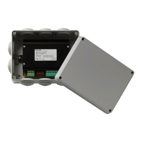
KAL734C Addressable 4-Relay Output Module
Installation Sheet
EN ES
IT
PT FR NL CS NO PL HU
1
EN: Installation instructions
Description
The KAL734C provides four potential-free relay outputs for the
fire system loop. Each relay allows for common (C), normally
open (NO), and normally closed (NC) contacts.
The module may be used with any device and the choice of
contact used will set the desired event.
Installation
Caution:
For general guidelines on system planning, design,
installation, commissioning, use and maintenance, refer to the
EN54:14 standard and local regulations.
Module Installation
Disconnect the fire system power supply and install the module
in the protective housing provided.
© 2014 UTC Fire & Security. All rights reserved.
Connect the loop cable shield wire to the earth screw.
The 24 V power supply for the module must be provided by an
auxiliary power source.
Connection
The module connectors, DIP switch, and status LED are
shown in Figure 1:
1.
Earth screw
2.
Status LED
3.
Loop connectors
4.
Auxiliary power supply connectors
5.
DIP switch
6.
Relay output connectors 1 to 4 (C, NC, NO)
Addressing
Each module requires a numeric address between 128 and
252 for identification purposes. This is set using DIP switches
1-7. See the address table at the end of this document.
1 / 16
P/N 10-5151-501-104-01 • ISS 28NOV14
Publicidad
Tabla de contenido

Resumen de contenidos para Kilsen KAL734C
- Página 1 The 24 V power supply for the module must be provided by an auxiliary power source. Description Connection The KAL734C provides four potential-free relay outputs for the The module connectors, DIP switch, and status LED are fire system loop. Each relay allows for common (C), normally shown in Figure 1: open (NO), and normally closed (NC) contacts.
-
Página 2: Descripción
ES: Instrucciónes de instalación Specifications Descripción Operating voltage 22 to 38 VDC El módulo KAL734C proporciona cuatro salidas de relé libre de Loop current consumption: potencial al bucle del sistema de incendios. Cada relé permite at 24 VDC (standby) 110 µA la instalación de contactos comunes (C), normalmente abiertos... -
Página 3: It: Istruzioni Di Installazione
Configure el módulo como salida que activará un detector o un pulsador. Il modulo KAL734C dispone di quattro uscite relè libere da potenziale per il loop di un sistema antincendio. Ciascun relè Active un detector o un pulsador asociado al módulo. -
Página 4: Specifiche Tecniche
Descrição Se il LED di stato e la centrale antincendio non si attivano O KAL734C fornece quatro saídas de relé sem potencial ao durante il test, controllare tutti i collegamenti e verificare loop do sistema de detecção de incêndios. Cada relé permite l’indirizzo del modulo. - Página 5 Description Se o LED de estado e o painel de controlo não Le module KAL734C fournit quatre sorties de relais libre de assinalarem o teste, devem ser inspeccionadas todas as potentiel à la boucle du système de détection d’incendie.
-
Página 6: Caractéristiques Techniques
Beschrijving Caractéristiques techniques De KAL734C heeft vier potentieel vrije relaisuitgangen voor de brandmeldsysteemlus. Elk relais heeft drie contactpunten die kunnen worden gekozen: gemeenschappelijk (C), normaal Tension de fonctionnement 22 à 38 VCC open (NO) en normaal gesloten (NC). -
Página 7: Cs: Návod K Instalaci
Als het statuslampje en het controlepaneel hier niet op reageren, moet u alle verbindingen en het moduleadres Popis testen. KAL734C poskytuje čtyři bezpotenciálové reléové výstupy pro smyčku protipožárního systému. Každé relé umožňuje Technische specificaties používat společné (C), rozpínací (NC) a spínací (NO) vývody kontaktů. - Página 8 Driftsspenning 22 til 38 V likestrøm Beskrivelse Sløyfestrømforbruk: ved 24 V likestrøm (standby) 110 µA KAL734C inneholder fire potensialfrie reléutganger for ved 35 V likestrøm (standby) 135 µA Alarm <10 mA brannsystemsløyfen. Hvert relé har kontakter av typen felles (C), normalt åpen (NO) og normalt lukket (NC).
-
Página 9: Pl: Instrukcja Montażu
PL: Instrukcja montażu Dane techniczne Opis Napięcie pracy 22 do 38 VDC KAL734C umożliwia dołączenie 4 bezpotecjałowych wyjść Pobór prądu w pętli przekaźnikowych do pętli adresowalnego systemu 110 μA 24 VDC (czuwanie) pożarowego. Każdy przekaźnik posiada styk normalnie 135 μA... -
Página 10: Certyfikaty I Zgodność
Ha az állapotjelző LED és a kezelőpult nem a kellő módon reagál, ellenőrizze az összes csatlakozót és modulcímet.. Leírás A KAL734C négy feszültségmentes relékimenetet biztosít a Műszaki adatok címezhető tűzérzékelőrendszer-hurokhoz. Minden relének van közös (C), alaphelyzetben nyitott (NO) és alaphelyzetben zárt (NC) érintkezője. - Página 11 Minősítő szervezet 0370 Teljesítménynyilatkozat 360-4109-0899 száma Az első CE megfelelősség éve Termék azonosító KAL734C Tervezett felhasználás Lásd a teljesítménynyilatkozat 3 pontjában Főbb jellemzők Lásd a teljesítménynyilatkozat 9 pontjában Gyártó UTC CCS Manufacturing Polska Sp. Z o.o. Ul. Kolejowa 24. 39-100 Ropczyce, Lengyelország...
- Página 12 12 / 16 P/N 10-5151-501-104-01 • ISS 28NOV14...
- Página 13 P/N 10-5151-501-104-01 • ISS 28NOV14 13 / 16...
- Página 14 14 / 16 P/N 10-5151-501-104-01 • ISS 28NOV14...
- Página 15 P/N 10-5151-501-104-01 • ISS 28NOV14 15 / 16...
- Página 16 16 / 16 P/N 10-5151-501-104-01 • ISS 28NOV14...


