Tabla de contenido
Publicidad
Enlaces rápidos
sauder.com
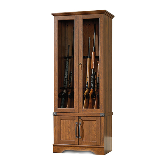
Gun Cabinet
Carson Forge Collection | Model 419575
Need help? Visit Sauder.com to view video assembly tips or chat with a live rep.
Prefer the phone? Call 1-800-523-3987.
Share your journey!
WARNING
This cabinet provides limited
security for long guns and is
not intended for handguns,
youth guns or other fi rearms.
NOTE: THIS INSTRUCTION
BOOKLET CONTAINS IMPORTANT
SAFETY INFORMATION.
PLEASE READ AND KEEP FOR
FUTURE REFERENCE.
English pg 1-32
Français pg 33-36
Español pg 37-40
Lot # 388442
04/26/16
Purchased: __________________
Be sure to give us a ring before
making any returns. 1-800-523-3987
Publicidad
Tabla de contenido

Manuales relacionados para Sauder Carson Forge 419575


Resumen de contenidos para Sauder Carson Forge 419575
- Página 1 Carson Forge Collection | Model 419575 NOTE: THIS INSTRUCTION BOOKLET CONTAINS IMPORTANT SAFETY INFORMATION. Need help? Visit Sauder.com to view video assembly tips or chat with a live rep. PLEASE READ AND KEEP FOR FUTURE REFERENCE. Prefer the phone? Call 1-800-523-3987.
- Página 2 • Do not push furniture, especially on a designed and equipped with casters. improperly moved. carpeted fl oor. Have a friend help you lift • Physical injury. Furniture can be very heavy. the item and set it in place. Page 2 419575 www.sauder.com/services...
-
Página 3: Part Identifi Cation
SKIRT (1) FRONT MOLDING (1) RIGHT MOLDING (1) LEFT MOLDING (1) RACK MOLDING (1) STOCK REST (1) BOTTOM MOLDING (1) HINGE MOLDING (2) W END MOLDING (2) DOOR STOP (1) SHELF MOLDING (1) SIDE MOLDING (2) www.sauder.com/services 419575 Page 3... - Página 4 fi rearms. 373366 (Refer to the last step for proper location and application) BAR RECEIVER/ DIVIDER - 9 CAM COVER - 22 PLUG SET - 2 Page 4 419575 www.sauder.com/services...
-
Página 5: Tabla De Contenido
BLACK 2" FLAT HEAD SCREW - 4 101S BLACK 1-1/2" FLAT HEAD SCREW - 4 113S BLACK 1-15/16" FLAT HEAD SCREW - 4 118S BLACK 1-3/8" PAN HEAD SCREW - 14 RECOMMENDED PADLOCK - NOT PROVIDED www.sauder.com/services 419575 Page 5... - Página 6 Look for this icon. It means a Step 1 video assembly tip is available at www.sauder.com/services/tips Insert a CONNECTOR SCREW (8S) into each HIDDEN å CONNECTOR (5F). Step 2 Assemble your unit on a carpeted fl oor or on the empty å...
-
Página 7: Important
FELT STRIP off with your scissors. NOTE: When pulling back the release paper on the FELT STRIP, be sure you do not pull on any of the FELT STRIP already å applied to the BARREL REST. www.sauder.com/services 419575 Page 7... - Página 8 DOWELS into these edges. DOWEL into the HIDDEN CAM. Arrow (37 used) Arrow Hole Arrow The arrow in the HIDDEN CAM must point toward the These holes hole in the edge of the board. must be here. Page 8 419575 www.sauder.com/services...
- Página 9 Step 5 Tap two MOLDING CONNECTORS (17F) into the notches å in the MOLDINGS (P, Q, and R). Use your hammer to tap the MOLDING CONNECTORS (17F) into the notches in the MOLDINGS. Flat end Flat end www.sauder.com/services 419575 Page 9...
- Página 10 Step 6 Fasten the MOLDINGS (P, Q, and R) to the TOP (D). Use å six SILVER 1-1/8" FLAT HEAD SCREWS (10S). SILVER 1-1/8" FLAT HEAD SCREW (6 used in this step) Long rounded edge Page 10 419575 www.sauder.com/services...
- Página 11 Step 7 Insert three DOUBLE DOWELS (22F) into the BACKS (I). å Fasten the BACKS (I) together. Tighten six HIDDEN CAMS. å These holes must be here. These holes must be here. www.sauder.com/services 419575 Page 11...
- Página 12 HIDDEN CONNECTORS, insert your screwdriver, at an angle, into the slot in the HIDDEN CONNECTOR. While pushing the screw into the hole of the adjoining part, turn the screwdriver clockwise to tighten. Surface with HIDDEN CONNECTORS Page 12 419575 www.sauder.com/services...
- Página 13 Fasten two DIVIDERS (89M) to the ENDS (A and B) exactly as å shown. Use four BROWN 1" FLAT HEAD SCREWS (12S). BROWN 1" FLAT HEAD SCREW (4 used in this step) Edge with CAM DOWELS www.sauder.com/services 419575 Page 13...
- Página 14 Tighten Risk of damage or Arrow injury. HIDDEN CAMS must be completely Arrow Maximum tightened. HIDDEN 210 degrees CAMS that are not completely tightened may loosen, and parts may separate. To Minimum completely tighten: 190 degrees Page 14 419575 www.sauder.com/services...
- Página 15 Fasten these seven DIVIDERS (89M) to the RACK MOLDING (S). Use å fourteen BLACK 1-3/8" PAN HEAD SCREWS (118S). 118S Unfi nished edge BLACK 1-3/8" PAN HEAD SCREW (14 used in this step) www.sauder.com/services 419575 Page 15...
- Página 16 Tighten one HIDDEN CONNECTOR. Flip the RACK MOLDING (S) before inserting. Edge with CAM DOWELS i t h o f a c S u r D E N H I D Maximum Arrow 210 degrees Minimum 190 degrees Page 16 419575 www.sauder.com/services...
-
Página 17: Silver 1-1/8" Flat Head Screw
DOWELS Use the SILVER 1-1/8" FLAT HEAD SCREWS here. S u r f a c H I D D E N i t h 113S Groove BLACK 1-15/16" FLAT HEAD SCREW (4 used in this step) www.sauder.com/services 419575 Page 17... - Página 18 Fasten the MOLDINGS (Q and R) on the TOP (D) to the å ENDS (A and B). Tighten four HIDDEN CAMS. Maximum Arrow 210 degrees Insert the DOOR STOP (4I) into the exact hole shown in å the FRONT MOLDING (P). Minimum 190 degrees Page 18 419575 www.sauder.com/services...
- Página 19 å Tighten two HIDDEN CAMS. Maximum Arrow 210 degrees Minimum 190 degrees Edge with CAM DOWELS These edges must be even. i t h f a c S u r D E N H I D www.sauder.com/services 419575 Page 19...
- Página 20 DOWELS Edge with CAM DOWELS S u r f a c H I D D E N i t h i t h o f a c S u r D E N H I D Page 20 419575 www.sauder.com/services...
- Página 21 Step 17 Fasten the LOWER ENDS (C and E) to the SHELF (H). å Tighten four HIDDEN CAMS. Maximum Arrow 210 degrees Minimum 190 degrees www.sauder.com/services 419575 Page 21...
- Página 22 å remove it and slide it on again. Shoulder Apply pressure with your hands as you guide the MOLDINGS over the SCREWS and onto the ENDS. BLACK 2" FLAT HEAD SCREW (4 used in this step) Page 22 419575 www.sauder.com/services...
- Página 23 Maximum Arrow 210 degrees Minimum 190 degrees The hole on the other surface of the DOOR STOP (X) should be closer to the top edge SILVER 1-1/8" FLAT HEAD SCREW (2 used for the DOOR STOP) www.sauder.com/services 419575 Page 23...
- Página 24 å as shown in the enlarged diagram below. 101S BLACK 1-1/2" FLAT HEAD SCREW (4 used in this step) The END MOLDINGS (W) should overhang the LOWER ENDS (C and E) slightly. Surface with more holes Page 24 419575 www.sauder.com/services...
- Página 25 BRACKETS on the SKIRT and into the holes in the LOWER ENDS and BOTTOM. BLACK 9/16" LARGE HEAD SCREW (10 used in this step) Maximum Arrow 210 degrees Minimum Unfi nished surface 190 degrees www.sauder.com/services 419575 Page 25...
- Página 26 Fasten the LOCK BRACKETS (5J) to the SHELF (H). Use two BLACK 9/16" LARGE HEAD SCREWS (1S). å NOTE: Be sure to position the BRACKETS exactly as shown in the enlarged diagram. å BLACK 9/16" LARGE HEAD SCREW (4 used in this step) Use the exact holes shown for each BRACKET. Page 26 419575 www.sauder.com/services...
-
Página 27: Black 1/2" Flat Head Screw
BLACK 1/2" FLAT HEAD SCREWS (11S). Fasten four CURVED HINGES (14H) to the SMALL DOORS (M å BLACK 1/2” FLAT HEAD SCREW and N). Use eight BLACK 1/2" FLAT HEAD SCREWS (11S). (20 used in this step) www.sauder.com/services 419575 Page 27... -
Página 28: Silver 5/8" Machine Screw
FRONT MOLDING (P) and DOOR STOP (X). BLACK 1/2" FLAT HEAD SCREW (1 used for the STRIKE PLATE) BROWN 1" FLAT HEAD SCREW (4 used for the SLIDE CATCHES) SILVER 5/8" MACHINE SCREW (4 used for the PULLS) Page 28 419575 www.sauder.com/services... - Página 29 å screw one turn and move the DOORS in or out, as needed. Tighten the mounting screw after making adjustments. Mounting screw (depth) Adjusting screw (horizontal) (vertical adjustment) Mounting screw (depth) Adjusting screw (horizontal) (vertical adjustment) www.sauder.com/services 419575 Page 29...
- Página 30 If you want to position the TUBE SET higher, use these set of holes BLACK 9/16" PAN HEAD SCREW (4 used in this step) This hole is used for the recommended padlock. 3-1/2" 12-3/4" WRONG 18-1/2" 9-1/8" Page 30 419575 www.sauder.com/services...
-
Página 31: Silver 5/8" Flat Head Screw
(6 used in this step) Metal bar Key extension NOTE: For LOCK (13J), the METAL BAR will bend toward the KEY EXTENSION. Metal bar Key extension NOTE: For LOCK (12J), the METAL BAR will bend away from the KEY EXTENSION. www.sauder.com/services 419575 Page 31... - Página 32 • Always comply with safe gun storage laws and recommendations. This cabinet/ bench provides limited security for long guns, and is not intended for handguns and other fi rearms. 373366 100 lbs. 100 lbs. (22 used) To cover HIDDEN CAMS Page 32 419575 www.sauder.com/services...
-
Página 33: Liste De Pièces
EXTRÉMITÉ DROITE ..........1 13H CHARNIÈRE ..............6 pour future référence. EXTRÉMITÉ GAUCHE ..........1 14H CHARNIÈRE INCURVÉE .........4 Pour contacter Sauder EXTRÉMITÉ DROITE INFÉRIEURE ....1 ARRÊT DE PORTE ............1 en ce qui concerne cet DESSUS ................1 PLAQUE DE BUTÉE ............1 EXTRÉMITÉ... - Página 34 Enfoncer deux CONNECTEURS DE MOULURE (17F) dans les crans des MOULURES (P, Q et R). ÉTAPE 6 Fixer les MOULURES (P, Q et R) au DESSUS (D). Utiliser six VIS TÊTE PLATE 28 mm ARGENTÉES (10S). Page 34 419575 www.sauder.com/services...
- Página 35 Enfi ler les MOULURES LATERALES (Z) sur la TABLETTE (H). Aligner les rainures des MOULURES sur les têtes des VIS dans la TABLETTE. REMARQUE : Si la MOULURE soulève au-dessus les VIS, l'enlever et l'enfi ler de nouveau. www.sauder.com/services 419575 Page 35...
- Página 36 REMARQUE : Prière de lire les informations importantes sur la sécurité fi gurant sur les pages arrière du manuel d’instructions. Ceci complète l'assemblage. Nettoyer à l’ a ide d’une encaustique pour meubles ou d’un chiff on humide. Essuyer. Page 36 419575 www.sauder.com/services...
-
Página 37: Vitrina Para Armas
EXTREMO DERECHO INFERIOR .....1 SEGURO GRANDE ............1 pour future référence. PANEL SUPERIOR ............1 53K TIRADOR ................2 Pour contacter Sauder EXTREMO IZQUIERDO INFERIOR ....1 ETIQUETA DE ADVERTENCIA ......1 en ce qui concerne cet FONDO .................1 (Consulte el último paso para la ubicación e élément, faire référence... - Página 38 CABEZA REDONDA de 35 mm (118S). muescas de las MOLDURAS (P, Q y R). PASO 6 Fije las MOLDURAS (P, Q y R) al PANEL SUPERIOR (D). Utilice seis TORNILLOS PLATEADOS DE CABEZA PERDIDA de 28 mm (10S). Page 38 419575 www.sauder.com/services...
- Página 39 Deslice las MOLDURAS LATERALES (Z) sobre el ESTANTE (H). Alinee las ranuras de las MOLDURAS sobre las cabezas de los TORNILLOS del ESTANTE. NOTA: Si la MOLDURA se levanta de los TORNILLOS, retírela y deslícela sobre la parte otra vez. www.sauder.com/services 419575 Page 39...
- Página 40 NOTA: Por favor, lea las páginas de atrás del folleto de instrucciones en cuanto a importante información de seguridad. Esto completa el ensamblaje. Limpie con su pulimento para muebles preferido o un paño húmedo. Seque con un paño. Page 40 419575 www.sauder.com/services...
- Página 41 Se faire aider par une autre n'en est pas équipé. • Blessure physique. Le meuble peut être personne pour soulever l'élément et le très lourd. mettre en place. www.sauder.com/services 419575 Page 41...
- Página 42 Pide la ayuda de otra posible. persona para levantar la unidad y colocarla • Lesión física. Los muebles pueden ser en lugar. muy pesado. Page 42 419575 www.sauder.com/services...
-
Página 43: Garantie Limitée De 5 Ans
à compter de la date d'achat la première fois et qui sont signalés à Sauder dans les limites de couverture de la contre tout défaut de matériaux ou de fabrication des composantes de mobilier Sauder. - Página 44 Dear Valued Customer: So, how did it go? Thanks so much for choosing Sauder® furniture. I hope the Set a world record for speed? purchase and assembly process was a positive experience Feeling good about yourself? and you feel good about the furniture you just built. If you Nice.