Tabla de contenido
Publicidad
Idiomas disponibles
Idiomas disponibles
Enlaces rápidos
DE
Vor dem Einbau des Sets die Einbau- und
Betriebsanleitung vollständig lesen!
Einbau, Inbetriebnahme, Bedienung und
Wartung darf nur durch geschultes Fach-
personal durchgeführt werden!
Die Einbau- und Betriebsanleitung sowie
alle mitgeltenden Unterlagen sind an den
Anlagenbetreiber weiterzugeben!
Inhalt
1 Allgemeine Hinweise . . . . . . . . . . . . . . . 1
2 Sicherheitshinweise . . . . . . . . . . . . . . . 2
4 Technische Daten . . . . . . . . . . . . . . . . . 3
5 Funktion . . . . . . . . . . . . . . . . . . . . . . . . 3
6 Montage und Inbetriebnahme . . . . . . . . 4
7 Zubehör . . . . . . . . . . . . . . . . . . . . . . . . 6
8 Wartung und Pflege . . . . . . . . . . . . . . . . 7
9 Gewährleistung . . . . . . . . . . . . . . . . . . . 7
10 Diagramme . . . . . . . . . . . . . . . . . . . . . . 7
OVENTROP GmbH & Co. KG
Paul-Oventrop-Straße 1
D-59939 Olsberg
Telefon +49 (0)2962 82-0
Telefax +49 (0)2962 82-400
E-Mail mail@oventrop.de
Internet www.oventrop.com
Eine Übersicht der weltweiten Ansprechpartner
finden Sie unter www.oventrop.de.
Premium Armaturen + Systeme
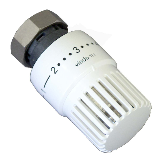
Set „vindo TH" + „Multiflex F"
Einbau- und Betriebsanleitung für Fachpersonal
Abb .1 Set, Durchgangsform, G
1 Allgemeine Hinweise
1.1 Informationen zur Einbau- und Betriebs-
anleitung
Diese Einbau- und Betriebsanleitung dient dem
geschulten Fachpersonal dazu, das Ventil-Set
fachgerecht zu installieren und in Betrieb zu
nehmen . Mitgeltende Unterlagen - Anleitungen
aller Anlagenkomponenten sowie geltende
technische Regeln - sind einzuhalten .
1.2 Aufbewahrung der Unterlagen
Diese Einbau- und Betriebsanleitung ist vom Anla-
genbetreiber zum späteren Gebrauch aufzubewah-
ren .
1.3 Urheberschutz
Die Einbau- und Betriebsanleitung ist urheber-
rechtlich geschützt .
Technische Änderungen vorbehalten.
171581380
04/2017
⁄
ÜM x G
⁄
AG
3
3
4
4
1
Publicidad
Capítulos
Tabla de contenido

Manuales relacionados para oventrop vindo TH


Resumen de contenidos para oventrop vindo TH
-
Página 1: Tabla De Contenido
Premium Armaturen + Systeme Set „vindo TH“ + „Multiflex F“ Einbau- und Betriebsanleitung für Fachpersonal Vor dem Einbau des Sets die Einbau- und Betriebsanleitung vollständig lesen! Einbau, Inbetriebnahme, Bedienung und Wartung darf nur durch geschultes Fach- personal durchgeführt werden! Die Einbau- und Betriebsanleitung sowie... -
Página 2: Sicherheitshinweise
1.4 Symbolerklärung Das Set, bestehend aus ZB-Absperrverschrau- Hinweise zur Sicherheit sind durch Symbole bung „Multiflex F“ und Thermostat „vindo TH“, gekennzeichnet . Diese Hinweise sind zu befol- wird in Zentralheizungs- oder Kühlanlagen mit gen, um Unfälle, Sachschäden und Störungen geschlossenen Kreisläufen zur Regelung der zu vermeiden . Raumtemperatur an Heizkörpern mit integrier- ter Ventilgarnitur mit Rohrabstand 50 mm eingesetzt . GEFAHR Jede darüber hinausgehende und/oder ander- GEFAHR weist auf eine unmittelbar sartige Verwendung des Ventil-Sets ist untersagt gefährliche Situation hin, die zum Tod oder und gilt als nicht bestimmungsgemäß . Ansprü- zu schweren Verletzungen führen wird, che jeglicher Art gegen den Hersteller und/oder wenn die Sicherheitsmaßnahmen nicht seine Bevollmächtigten wegen Schäden aus befolgt werden . nicht bestimmungsgemäßer Verwendung können nicht anerkannt werden . -
Página 3: Technische Daten
4.2 Abmessungen nur unter Vorbehalt annehmen . Reklamation einleiten . Dabei Reklamationsfristen beachten . 3.2 Lagerung Das Set nur unter folgenden Bedingungen lagern: – N icht im Freien . Trocken und staubfrei aufbewahren . – K einen aggressiven Medien oder Hitzequel- len aussetzen . – V or Sonneneinstrahlung und übermäßiger mechanischer Erschütterung schützen . Abb . 2 Durchgangsform – L agertemperatur: –20°C bis +60°C, relative Luftfeuchtigkeit: max . 95 % 3.3 Verpackung Sämtliches Verpackungsmaterial ist umwelt-... -
Página 4: Montage Und Inbetriebnahme
die Anschlussstutzen des Heizkörpers einschie- ben . Die ZB-Absperrverschraubung spannungsfrei an den Heizkörper schrauben . Die Überwurfmuttern an der Verbindung zum Heizkörper mit einem Drehmoment von 20 - 30 Nm anziehen . Auf Zugänglichkeit der Absper- rungen achten . Abb . 4 Ventilgarnitur mit G ⁄ IG 6.1.1 Rohrleitungsmontage Bei der Montage der Rohrleitungen auf parallele und spannungsfreie Zuführung achten . Die Position des Vor- und Rücklaufanschlusses ist an der Verschraubung frei wählbar, diese ist ggf . vom Heizkörpertyp abhängig . Entsprechende Produktbeschreibung beachten . Für den Anschluss von Kupfer-, Präzisionsstahl-, Edelstahl-, Kunststoffrohr, sowie „Copipe“ Mehrschichtverbundrohr, ist das Oven- Abb . 5 Ventilgarnitur mit G ⁄... - Página 5 ACHTUNG ca . 28°C / 82°F Bei der Montage kein zusätzliches Fett ca . 24°C / 75°F oder Öl verwenden, da es die Dichtungs- materialien im Ventil angreift . ca . 20°C / 68°F Die Einzelteile sind bereits werksseitig ca . 16°C / 61°F geölt . ca . 12°C / 54°F 6.2 Absperren ca . 7°C / 45°F Die ZB-Absperrverschraubung mit einem geeigneten Schraubendreher durch Rechts- drehen der beiden Absperrspindeln, um 90° bis zum Anschlag, schließen . (Schlitz der Absperrspindel quer zur Durchflussrichtung) Abb . 6 Temperaturskala Thermostat „vindo TH“ 6.3 Montage des Thermostaten 6.3.1 Thermostat Begrenzen und Blockieren Der Einstellbereich des Thermostaten kann ACHTUNG...
-
Página 6: Zubehör
7 Zubehör 2 . Z ur unteren Begrenzung wird ein Element, wie abgebildet, in die Position eine Nut vor Für die Verkleidung der ZB-Absperrverschrau- der Merkzahl „2“ eingesteckt (Abb . 8) . bung bietet Oventrop eine passende Design-Ab- deckung (Art .-Nr . 1015896) an . Nach Abschluss der Montage die Design-Ab- deckung montieren (Abb . 11) . 1 . D as Halteelement von der Wandseite aus auf die Überwurfmuttern schieben . 2 . D ie Abdeckung von vorne auf die Armatur Abb . 8 und das Halteelement aufstecken und durch Zusammendrücken einrasten . 3 . Z ur oberen Begrenzung des Einstellbereiches, wird das zweite Element, in die Position eine Nut nach der Merkzahl „4“ eingesteckt... -
Página 7: Gewährleistung
9 Gewährleistung Es gelten die zum Zeitpunkt der Lieferung gültigen Gewährleistungsbedingungen von Oventrop . 10 Diagramm Massenstrom q m [kg/h]... -
Página 8: General Information
Valves, controls + systems Set “vindo TH” + “Multiflex F” Installation and operating instructions for the specialised installer Read installation and operating instructions in their entirety before installing the set ! Installation, initial operation and maintenance must only be carried out by... -
Página 9: Symbol Explanation
1.4 Symbol explanation with a distance of 50 mm between the pipe Safety guidelines are displayed by symbols . centres . These guidelines are to be observed to avoid Any use of the set outside the above application accidents, damage to property and malfunctions . will be considered as non-compliant and misuse . Claims of any kind against the manufacturer DANGER and/or his authorised representatives, regarding damages caused by incorrect use, cannot be DANGER indicates an imminent dangerous accepted . situation which will lead to death or serious The observance of the installation and operating injury if the safety guidelines are not instructions is part of the compliance terms . observed . 2.2 Possible dangers at the installation location and during transport WARNING The case of an external fire was not taken into... -
Página 10: Technical Data
4.2 Dimensions 3.2 Storage The set must only be stored under the following conditions: – D o not store in open air, keep dry and free from dust . – D o not expose to aggressive fluids or heat sources . – P rotect from direct sunlight and mechanical agitation . – Storage temperature: –20 °C up to +60 °C – Max . relative humidity of air: 95 % Illustr . 2 Straight pattern 3.3 Packaging Packaging material is to be disposed of in an environmentally friendly manner . 4 Technical data 4.1 Performance data Operating temperature t 2°C up to 120°C ( for short periods... -
Página 11: Installation And Initial Operation
When installing the pipework, please make sure that the pipes run in parallel and are free from tension . The position of the supply and return pipe is optional and depends on the type of radiator . Please observe the corresponding product descriptions . For the connection of copper, precision steel, stainless steel and plastic pipes as well as the composition pipe “Copipe”, the Oventrop compression fittings are to be used (alternatively, Illustr . 5 Distributor with G ¾ male thread the compression fittings of other manufacturers according to DIN EN 16313 (cone “Euro”) – except for the composition pipe “Copipe” – The thermostat “vindo TH“ together with the which are suitable for the connection to male distributor of the radiator is a proportional thread G ¾ according to DIN EN 16313 (cone... - Página 12 NOTICE approx . 28°C / 82°F Do not use any greasing agents or oil for approx . 24°C / 75°F the installation, as these can destroy the valve seals . approx . 20°C / 68°F The individual components are lubricated approx . 16°C / 61°F at works . approx . 12°C / 54°F 6.2 Isolating approx . 7°C / 45°F Close the ZB isolating fitting with a suitable screwdriver by turning the two isolating stems clockwise by 90° until stop . (Slot of the isolating stem perpendicular to the flow direction .) Illustr . 6 Temperature scale thermostat 6.3 Installation of the thermostat “vindo TH“...
-
Página 13: Accessory
7 Accessory 2 . T o limit the minimum control range, one limiting clip should be fitted into the groove Oventrop offers a suitable design cover (item immediately before figure “2” (illustr . 8) . no . 1015896) for panelling the ZB isolating fitting . Mount the design cover after installation has been completed (illustr . 11) . 1 . S lip the fixing element onto the collar nuts from the side of the wall . 2 . P ush the cover onto the fitting and the fixing Illustr . 8 element from the front and push them together until they click into position . 3 . T o limit the maximum control range, the second limiting clip should be fitted into the groove immediately after figure “4” (illustr . -
Página 14: Warranty
9 Warranty Oventrops warranty conditions valid at the time of supply are applicable . 10 Chart Flow rate V · [l/s]... -
Página 15: Indicazioni Generali
“Premium” Valvole + Sistemi Set „vindo TH“ + „Multiflex F“ Istruzioni d‘uso e installazione per personale qualificato Prima di installare il set, leggere attentamente le istruzioni per l’uso e l’installazione! L’installazione, la messa in servizio e la manutenzione devono essere eseguite esclusivamente da personale qualificato! Le istruzioni per l’uso e l’installazione,... -
Página 16: Legenda Dei Simboli
1.4 Legenda dei simboli per il controllo della temperatura ambiente in Le avvertenze riguardanti la sicurezza sono abbinamento a radiatori con gruppo valvola contrassegnate da simboli . Questi avvisi devono integrato e attacco centrale tubazioni con essere rispettati, per evitare infortuni, danni a interasse di 50mm . materiali e guasti . È vietata ogni forma di utilizzo diversa da quelle summenzionate ed è considerata non conforme alla destinazione d’uso del prodotto . Reclami PERICOLO di qualsiasi tipo contro il produttore e/o PERICOLO viene visualizzato in una rappresentati autorizzati in merito a danni situazione di pericolo imminente, che può... -
Página 17: Dati Tecnici
4.2 Dimensioni 3.2 Stoccaggio Stoccare il set seguendo le indicazioni a seguire: – N on posizionare all’aperto, custodire in un luogo asciutto e privo di polvere . – N on esporre a liquidi aggressivi o fonti di calore . – P roteggere dai raggi solari e da vibrazioni meccaniche . – T emperatura di conservazione: da –20°C fino a +60°C, – U midità relativa dell’aria: max . 95 % Fig . 2 Versione diritta 3.3 Imballaggio Tutti i materiali d’imballaggio devono essere smaltiti nel rispetto dell’ambiente . 4 Dati tecnici 4.1 Dati prestazionali Temperatura d’esercizio t... -
Página 18: Installazione E Messa In Servizio
⁄ “ 6.1.1 Installazione delle tubazioni In fase di installazione delle tubazioni accertarsi che le stesse siano parallele e prive di tensioni . La posizione di mandata e ritorno è indifferente e dipende dal tipo di radiatore . Si prega di osservare le istruzioni dello stesso . Per installazioni con tubi in rame, acciaio di precisione, acciaio inox, plastica e multistrato „Copipe“ , utilizzare i raccordi di serraggio Oventrop (in alternativa, è possibile utilizzare Fig . 5 Gruppo valvola integrato con attacchi raccordi di serraggio di altro produttore – fatta filettati M G ⁄ “ sec .DIN EN 16313 (Eurocono) eccezione per il tubo in multistrato „Copipe“ La testa termostatica „vindo TH“, in abbinamento – che siano compatibili per il collegamento ad al gruppo valvola integrato sul radiatore, è un attacchi fil . M G ⁄... - Página 19 AVVERTENZA ca . 28°C / 82°F Durante la fase di installazione non ca . 24°C / 75°F utilizzare grassi od olii aggiuntivi, in quanto potrebbero danneggiare le guarnizioni ca . 20°C / 68°F della valvola . Tutti i componenti sono già ca . 16°C / 61°F stati lubrificati in fase di produzione . ca . 12°C / 54°F 6.2 Intercettazione ca . 7°C / 45°F Chiudere il gruppo valvola ZB con idoneo cacciavite, ruotando i due perni di intercettazione in senso orario di 90° fino alla fine . (Taglio del perno della valvola di intercettazione perpendicolare alla direzione...
-
Página 20: Accessori
7 Accessori 2 . P er limitare la posizione di “minima temperatura”, una delle clip di limitazione Oventrop propone un coprivalvola da design, dovrà essere inserita nella sede subito prima adatto alla copertura del gruppo valvola ZB (cod . alla posizione «2» (Fig . 8) . art . 1015896) . Installare il coprivalvola da design a lavori ultimati (Fig . 11) . 1 . I nfilare l’elemento di fissaggio sulle calotte – lato muro . 2 . P remere frontalmente il coprivalvola sulla valvola e sull’elemento di fissaggio, premerli Fig . 8 insieme fino a che non si avverte il click di fissaggio . -
Página 21: Garanzia
9 Garanzia Sono valide le condizioni di garanzia stabilite da Oventrop e in vigore al momento della fornitura . 10 Diagramma Portata q m [kg/h]... -
Página 22: Información General
Válvulas y Sistemas Premium Kit “vindo TH” + “Multiflex F” Instrucciones de instalación y funcionamiento para el instalador especializado ¡Lea estas instrucciones de instalación y funcionamiento en su totalidad antes de instalar el kit! ¡La instalación, puesta en marcha y mantenimiento debe ser llevada a cabo sólo... -
Página 23: Explicación De Símbolos
1.4 Explicación de símbolos radiadores con distribuidor integrado con una Las indicaciones de seguridad se muestran distancia de 50 mm entre centros de tuberías . mediante símbolos . Estas indicaciones deben Cualquier uso del kit fuera de la aplicación respetarse para evitar accidentes, daños a la anterior será considerado como no conforme propiedad y fallos de funcionamiento . y uso indebido . No se aceptarán reclamaciones de ningún tipo contra el fabricante y/o sus representantes autorizados por daños causados ¡PELIGRO! por uso incorrecto . PELIGRO indica una situación peligrosa El cumplimiento de las instrucciones de inminente que provocará la muerte o serios instalación y funcionamiento es parte del daños en caso de no seguir las indicaciones cumplimiento de términos . de seguridad . 2.2 Posibles peligros en el lugar de instalación o durante el transporte ¡AVISO! -
Página 24: Almacenamiento
4.2 Dimensiones 3.2 Almacenamiento El kit de válvula termostática debe almacenarse sólo en las siguientes condiciones: – N o almacenar a la intemperie, mantener en lugar seco y libre de suciedad . – N o exponer a fluidos agresivos o fuentes de calor . – P roteger de la luz directa del sol y de movimientos mecánicos . – T emperatura de almacenamiento: -20ºC hasta +60ºC – M áx . humedad relativa del aire: 95% Fig . 2 Diseño recto 3.3 Empaquetado... -
Página 25: Instalación Y Puesta En Marcha
6.1.1 Instalación de las tuberías Cuando se instalan las tuberías, por favor asegúrese de que las tuberías están en paralelo y libres de tensión . La posición del tubo de ida y de retorno es opcional y depende del tipo de radiador . Por favor, cumpla con las descripciones de producto correspondiente . Para la conexión a tubería de cobre, acero de precisión, acero inoxidable y plástico así como de tubo multicapa de Oventrop “Copipe”, deben Fig . 5 Distribuidor con rosca macho G ⁄ según utilizarse los racores de compresión de Oventrop DIN EN 16313 (“Euro” cono) (como alternativa pueden utilizarse los racores El termostato “vindo TH” combinado con el de compresión de otros fabricantes – excepto distribuidor del radiador es un controlador para el tubo multicapa “Copipe”- que sean... -
Página 26: Instalación Del Termostato
NOTA aprox . 28°C / 82°F No utilizar ningún agente lubricante o aprox . 24°C / 75°F grasa para la instalación, ya que puede destruir las juntas de la válvula . aprox . 20°C / 68°F Los componentes individuales vienen aprox . 16°C / 61°F lubricados de fábrica . aprox . 12°C / 54°F 6.2 Corte aprox . 7°C / 45°F Cierre el racor de corte ZB con un destornillador apropiado girando 90º los dos ejes de corte en sentido horario hasta el tope . (Ranura del eje de corte perpendicular a la dirección del caudal) . Fig . 5 Escala de temperatura del termostato “vindo TH” 6.3 Instalación del termostato 6.3.1 Limitación y bloqueo del termostato NOTA El rango de control del termostato se puede... -
Página 27: Accesorios
7 Accesorios 2 . P ara limitar el rango de control mínimo, uno de los clips limitadores debe colocarse en Oventrop ofrece una cubierta de diseño (art . nº la ranura inmediatamente anterior a la 1015896) para panelar el bloque de corte ZB . posición “2” (fig . 8) . Montar la cubierta de diseño cuando la instalación esté terminada (fig . 11) . 1 . D eslice el elemento de fijación sobre las tuercas desde el lado de la pared . 2 . E mpuje la cubierta sobre el racor y el elemento de fijación desde el frontal y empújelos juntos... -
Página 28: Garantía
9 Garantía Se aplican las condiciones de garantía de Oventrop válidas en el momento del suministro . 10 Curvas Caudal V · [l/s]... -
Página 29: Obecné Informace
Armatury + systémy Premium Sada „vindo TH“ + „Multiflex F“ Návod k montáži a obsluze pro řemeslníky Před použitím sady „vindo TH“ + „Multiflex F“ si pečlivě přečtěte návod k obsluze! Instalaci, uvedení do provozu, provoz a údržbu má povoleno provádět pouze kvalifikovaný... -
Página 30: Vysvětlení Symbolů
1.4 Vysvětlení symbolů teploty v uzavřených okruzích vytápění a Bezpečnostní pokyny jsou označeny symboly. chlazení. Rozteč potrubí 50 mm. Tyto pokyny jsou určeny pro používání, aby Je nepřípustné používat sadu ventilů pro další se zabránilo nehodám, škodám na majetku a a /nebo odlišné... -
Página 31: Technická Data
4.2 Rozměry 3.2 Skladování Sadu ventilů skladovat za následujících podmínek: – Neskladovat pod širým nebem. Uchovávat v suchém a bezprašném prostředí. – Nevystavovat agresivním kapalinám nebo zdrojům tepla. – Chránit před přímým slunečním zařízením a nadměrnými mechanickými otřesy. – Skladovací teplota: –20 °C až +60 °C, –... -
Página 32: Montáž A Uvedení Do Provozu
„Copipe“ kde je určeno připojení na EN 16313 (Eurokonus) AG G ⁄ dle DIN EN 16313 (Eurokonus). Termostatická hlavice „vindo TH“ a 1. Uřízněte potrubí na požadovanou délku termostatické ventily tvoří společně kolmo k ose trubky. proporcionální regulátory pracující bez 2. - Página 33 šroubováku otočením dvakrát doprava o 90° k zarážce. (Uzavírací vřeteno ventilu brání průtoku). Obr. 6 Teplotní stupnice termostatické hlavice 6.3 Montáž termostatických hlavic „vindo TH“ UPOZORNĚNÍ 6.3.1 Omezování a blokování termostatických hlavic Termostatické hlavice namontujte až po dokončení stavby, aby nedošlo k jejich Nastavení...
-
Página 34: Příslušenství
2. Pro spodní omezení nastavení, viz obrázek, je poloha drážky nastavena před označením Pro zakrytí ZB-uzavíracího šroubení nabízí „2“ (obr. 8). Oventrop designovou krytku (výr.č. 1015896). Designovou krytku namontujte po instalaci (obr. 11). 1. Nasuňte u stěny přídržnou část krytky na převlečné... -
Página 35: Záruka
9 Záruka Záruční podmínky firmy Oventrop jsou platné od okamžiku dodání výrobku. 10 Diagram hmotnostní tok q m [kg/h]...