Tabla de contenido
Publicidad
Idiomas disponibles
Idiomas disponibles
Enlaces rápidos
DE
Vor dem Einbau des TRV9-Sets die
Einbau- und Betriebsanleitung vollstän-
dig lesen!
Einbau, Inbetriebnahme, Bedienung und
Wartung darf nur durch geschultes Fach-
personal durchgeführt werden!
Die Einbau- und Betriebsanleitung sowie
alle mitgeltenden Unterlagen sind an den
Anlagenbetreiber weiterzugeben!
Inhalt
1 Allgemeine Hinweise ............................1
2 Sicherheitshinweise ............................. 2
Verpackung .......................................... 2
4 Technische Daten ................................. 3
5 Funktion ............................................... 3
6 Montage und Inbetriebnahme ............. 4
7 Wartung und Pflege ............................. 7
8 Gewährleistung .................................... 7
9 Diagramme .......................................... 8
OVENTROP GmbH & Co. KG
Paul-Oventrop-Straße 1
D-59939 Olsberg
Telefon +49 (0)2962 82-0
Telefax +49 (0)2962 82-400
E-Mail mail@oventrop.de
Internet www.oventrop.com
Eine Übersicht der weltweiten Ansprech-
partner finden Sie unter www.oventrop.de.
Premium Armaturen + Systeme
Einbau- und Betriebsanleitung für Fachpersonal
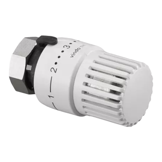
Abb.1 TRV9-Set, Eckform
1 Allgemeine Hinweise
1.1 Informationen zur Einbau- und
Betriebsanleitung
Diese Einbau- und Betriebsanleitung dient
dem geschulten Fachpersonal dazu, das
Ventil-Set fachgerecht zu installieren und in
Betrieb zu nehmen. Mitgeltende Unterlagen
- Anleitungen aller Anlagenkomponenten
sowie geltende technische Regeln - sind
einzuhalten.
1.2 Aufbewahrung der Unterlagen
Diese
Einbau-
ist vom Anlagenbetreiber zum späteren
Gebrauch aufzubewahren.
1.3 Urheberschutz
Die Einbau- und Betriebsanleitung ist urhe-
berrechtlich geschützt.
Technische Änderungen vorbehalten.
167370381
TRV9-Sets
und
Betriebsanleitung
10/2017 dd
1
Publicidad
Capítulos
Tabla de contenido

Manuales relacionados para oventrop TRV9


Resumen de contenidos para oventrop TRV9
-
Página 1: Tabla De Contenido
Premium Armaturen + Systeme TRV9-Sets Einbau- und Betriebsanleitung für Fachpersonal Vor dem Einbau des TRV9-Sets die Einbau- und Betriebsanleitung vollstän- dig lesen! Einbau, Inbetriebnahme, Bedienung und Wartung darf nur durch geschultes Fach- personal durchgeführt werden! Die Einbau- und Betriebsanleitung sowie... -
Página 2: Sicherheitshinweise
1.4 Symbolerklärung zungs- oder Kühlanlagen mit geschlossenen Hinweise zur Sicherheit sind durch Sym- Kreisläufen zur Regelung der Raumtempe- bole gekennzeichnet. Diese Hinweise sind ratur eingesetzt. zu befolgen, um Unfälle, Sachschäden und Jede darüber hinausgehende und/oder Störungen zu vermeiden. andersartige Verwendung des Ventil-Sets ist untersagt und gilt als nicht bestimmungs- gemäß. -
Página 3: Technische Daten
3.2 Lagerung GEFAHR Das Ventil-Set nur unter folgenden Bedin- gungen lagern: Es ist durch geeignete Maßnahmen (z. B. • Nicht im Freien. Trocken und staubfrei Sicherheitsventile) sicherzustellen, dass aufbewahren. die max. Betriebsdrücke sowie die max. • Keinen aggressiven Medien oder und min. -
Página 4: Montage Und Inbetriebnahme
Edelstahl, Präzisionsstahl ist. Kunststoff an das Thermostatventil und die ACHTUNG Verschraubung sind bei Oventrop für ver- schiedene Verbindungsarten (z.B. Schrau- Bei der Montage kein zusätzliches Fett ben) die Verbindungselemente zu beziehen oder Öl verwenden, da es die Dichtungs- (Zubehör, siehe Katalog „Ofix“ Verbindungs- materialien im Ventil angreift. - Página 5 Verbindungstechniken der hohen Rückstellkräfte der Ventilspindel Systemanbieter zu verwenden. Werden würden die Bauschutzkappe beschädi- Oventrop Mehrschicht-Verbundrohre vom gen. Montieren Sie eine Verschlusskappe Typ „Copipe“ verwendet, müssen diese mit aus Metall am Anschlussstutzen des Ven- der Verbindungstechnik „Cofit“ an die Ven- tilausgangs.
- Página 6 6.2.3 Voreinstellung der Verschraubung 1. Thermostat auf „5“ stellen. 1. Schutzkappe abschrauben. 2. Thermostat so ausrichten, dass die Mar- 2. Ventilkegel mit dem Sechskantschlüssel kierung gut sichtbar ist. SW 6 (1) durch Rechtsdrehen schließen 3. In dieser Stellung festhalten und die (Abb.
-
Página 7: Wartung Und Pflege
Die Armaturen sind wartungsfrei. 8 Gewährleistung Abb.7 Es gelten die zum Zeitpunkt der Lieferung 3. Zur oberen Begrenzung des Einstellbe- gültigen Gewährleistungsbedingungen von reiches, wird das zweite Element, in die Oventrop. Position eine Nut nach der Merkzahl „4“ eingesteckt (Abb. 8). Abb.8... -
Página 8: Diagramme
9 Diagramme 9.1 Thermostatventil „AV9“ Alle Ausführungen und Nennweiten bei 2K P-Abweichung Voreinstellung kv-Wert 0,05 0,09 0,14 0,20 0,26 0,32 0,43 0,57 0,67... - Página 9 9.2 Verschraubung „Combi 2“ Alle Ausführungen und Nennweiten Voreinstellung 0,25 0,75 kv-Wert 0,060 0,126 0,190 0,250 0,420 0,819 1,236 1,700...
-
Página 10: General Information
Illustr. 1 TRV9 set angle pattern Content 1 General information ......10 1 General information 2 Safety notes........11 3 Transport, storage and packaging ..11 1.1 Information regarding installation and... -
Página 11: Symbol Explanation
Safety in operation is only guaranteed if the completeness. TRV9 set is used correctly. Any damage must be reported immediately The valve set consisting of a thermostatic upon receipt. valve “AV 9”, a radiator lockshield valve “Combi 2” and a thermostat “vindo TH” is... -
Página 12: Technical Data
3.2 Storage DANGER The thermostatic valve set must only be stored under the following conditions: Suitable measures, e.g. safety valves, • Do not store in open air, keep dry and have to be taken to ensure that the max. free from dust. operating pressures and max. -
Página 13: Installation And Initial Operation
6.1.3 Pipework installation standardized metal and plastic NOTICE pipes Do not use any greasing agents or oil for Oventrop offers connection elements the installation, as these can destroy the for different types of connection (e.g. valve seals. screwed... -
Página 14: Initial Operation
Protect the valve outlet with a metal cap, out with the help of the “Cofit” fittings. for instance the Oventrop cap item no. 10669.. NOTICE When using compression fittings for 6.2.2 Setting of the thermostatic valve... - Página 15 6.2.3 Setting of the radiator lockshield 1. Set the thermostat to position “5”. valve 2. Align the thermostat so that the 1. Remove the protection cap. indicator mark is clearly visible. 2. Close the valve disc by turning a 3. Hold in this position and tighten the 6 mm spanner (1) to the right (illustr.
-
Página 16: Maintenance
Limitation Locking (for instance between figure “2” and “4”) (for instance to position “3”) 1. Slide the limiting clips out of the 1. Set the thermostat to position “3”. “parking position” (between figure “5” 2. Slide the limiting clips out of the and “0”, illustr. -
Página 17: Charts
9 Charts 9.1 Thermostatic valve “AV9” All models and sizes at 2 K P-deviation Presetting kv value 0.05 0.09 0.14 0.20 0.26 0.32 0.43 0.57 0.67... - Página 18 9.2 Radiator lockshield valve “Combi 2” All models and sizes Presetting 0,25 0,75 kv value 0.060 0.126 0.190 0.250 0.420 0.819 1.236 1.700...
-
Página 19: Indicazioni Generali
“Premium“ Valvole + Sistemi Set TRV9 Istruzioni d’uso e installazione per personale qualificato Prima di installare il set TRV9, leggere attentamente le istruzioni per l‘uso e l‘in- stallazione! L‘installazione, la messa in servizio e la manutenzione devono essere eseguite esclusivamente da personale qualificato! Le istruzioni per l‘uso e l‘installazione,... -
Página 20: Legenda Dei Simboli
1.4 Legenda dei simboli e una testa termostatica „vindo TH“, può essere utilizzato in impianti di riscaldamento Le avvertenze riguardanti la sicurezza sono o raffrescamento centralizzati a circuito contrassegnate da simboli. Questi avvisi chiuso, per il controllo della temperatura devono essere rispettati, per evitare infor- ambiente. -
Página 21: Dati Tecnici
3.2 Stoccaggio PERICOLO Stoccare il set TRV seguendo le indicazioni a seguire: Adottare le misure idonee (ad es. valvole • Non posizionare all‘aperto, custodire in di sicurezza) al fine di garantire che le un luogo asciutto e privo di polvere. pressioni di esercizio massime e che le •... -
Página 22: Installazione E Messa In Servizio
Durante la fase di installazione non uti- Oventrop dispone di raccordi per diversi tipi lizzare grassi od olii aggiuntivi, in quanto di collegamenti (ad es. attacchi filettati) per potrebbero danneggiare le guarnizioni tubi standard in rame, acciaio inox, acciaio della valvola. -
Página 23: Messa In Servizio
L’elevata forza di bilite dal fornitore del sistema. Se vengono ritorno dello stelo della valvola potrebbe utilizzati dei tubi multistrato Oventrop di tipo danneggiare il cappuccio di protezione. „Copipe“ il collegamento alla valvola dovrà Proteggere l’uscita della valvola con un essere eseguito con l’aiuto dei raccordi... - Página 24 6.2.3 Preregolazione del detentore a ser- 6.3 Installazione della testa termostatica vizio del radiatore 1. Rimuovere il cappuccio di protezione. AVVERTENZA 2. Chiudere l’otturatore conico con una Non installare la testa termostatica fino chiave esagonale CH 6 (6mm) (1) ad ultimazione dei lavori sull’intero can- ruotando a destra (Fig.
-
Página 25: Manutenzione
“2” (Fig. 7). 8 Garanzia Sono valide le condizioni di garanzia sta- bilite da Oventrop e in vigore al momento della fornitura. Fig.7 3. Per limitare la posizione di “massima temperatura”, la seconda clip di limita- zione dovrà... -
Página 26: Diagrammi
9 Diagrammi 9.1 Valvola termostatizzabile „AV9“ Tutti i modelli e diametri con 2K P-scostamento Preregolazione Portata Preregolazione Valore kv 0,05 0,09 0,14 0,20 0,26 0,32 0,43 0,57 0,67... - Página 27 9.2 Detentori „Combi 2“ Tutti i modelli e diametri Portata Preregolazione 0,25 0,75 Valore kv 0,060 0,126 0,190 0,250 0,420 0,819 1,236 1,700...
-
Página 28: Oventrop Gmbh & Co. Kg
Fig. 1 Kit TRV9 escuadra Contenido 1 Información general ... . . 28 1 Información general 2 Notas de seguridad . -
Página 29: Explicación De Símbolos
2.1 Uso correcto 3.1 Inspección del transporte La seguridad del funcionamiento sólo se Tras la recepción, comprobar los posibles garantiza si el kit TRV9 se utiliza correcta- daños causados durante el transporte y la mente. entrega de la totalidad del material. -
Página 30: Datos Técnicos
3.2 Almacenamiento PELIGRO El kit de válvula termostática debe alma- cenarse sólo en las siguientes condiciones: Deben tomarse las medidas adecuadas, • No almacenar a la intemperie, mantener ej. válvulas de seguridad, para asegurar en lugar seco y libre de suciedad. que la presión máxima de funciona- •... -
Página 31: Instalación Y Puesta En Marcha
6.1.3 Instalación con tubería metálica y NOTA plástica No utilizar ningún agente lubricante o Oventrop ofrece elementos de conexión grasa para la instalación, ya que puede para diferentes tipos de conexión (ej. destruir las juntas de la válvula. conexión roscada) de tubo de cobre Los componentes individuales vienen estándar, acero inoxidable, acero de preci-... -
Página 32: Instalación Para Tuberías Multicapa
(por ejemplo, cuando se retira el radiador). La alta fuerza de retorno del eje de la válvula causará daños al tapón protector. Proteja la salida de la válvula con un tapón metálico, por ejemplo, el tapón de Oventrop art. nº 10669.. -
Página 33: Ajuste Del Detentor
6.2.3 Ajuste del detentor 1. Coloque el termostato en posición “5”. 1. Retire el tapón protector 2. Alinee el termostato de tal forma que 2. Cierre la válvula girando una llave de 6 la marca indicadora sea claramente mm (1) hacia la derecha (fig. 3). visible. -
Página 34: Mantenimiento
3. Para limitar el rango de control máximo, 8 Garantía el segundo clip limitador debe colocarse Se aplican las condiciones de garantía de en la ranura inmediatamente posterior a Oventrop válidas en el momento del sumi- la posición “4” (fig. 8). nistro. Fig. 8... -
Página 35: Curvas
9 Curvas 9.1 Válvula termostática “AV9” Todos los modelos y tamaños con desviación-P 2K Preajuste Caudal V [l/s] Preajuste Valor kv 0,05 0,09 0,14 0,20 0,26 0,32 0,43 0,57 0,67... -
Página 36: Detentor "Combi 2" Todos Los Modelos Y Tamaños
9.2 Detentor “Combi 2” Todos los modelos y tamaños Caudal V [l/s] Preajuste 0,25 0,75 Valor kv 0,060 0,126 0,190 0,250 0,420 0,819 1,236 1,700... -
Página 37: Obecné Informace
Armatury + systémy Premium Sada - TRV9 Návod k montáži a obsluze pro řemeslníky Před použitím sady TRV9 si pečlivě přečtěte návod k obsluze! Instalaci, uvedení do provozu, provoz a údržbu má povoleno provádět pouze kvalifikovaný personál! Je potřeba si prohlédnout návod k použití... -
Página 38: Vysvětlení Symbolů
1.4 Vysvětlení symbolů teploty v uzavřených okruzích vytápění Bezpečnostní pokyny jsou označeny sym- a chlazení. boly. Je nepřípustné používat sadu ventilů Tyto pokyny jsou určeny pro používání, aby pro další a /nebo odlišné účely, než pro které se zabránilo nehodám, škodám na majetku jsou určeny. -
Página 39: Technická Data
3.2 Skladování NEBEZPEČÍ Sadu ventilů skladovat za následujících podmínek: Je potřeba zajistit vhodná opatření (např. • Neskladovat pod širým nebem. Uchová- bezpečnostní ventily), aby max. provo- vat v suchém a bezprašném prostředí. zní tlaky a minimální teploty nebyly pře- • Nevystavovat agresivním kapalinám kročeny ani podkročeny. -
Página 40: Montáž A Uvedení Do Provozu
Při instalaci nesmí být použity žádné tuky statické ventily a šroubení se používají nebo oleje, protože může dojít k poško- různé druhy připojení firmy Oventrop (např. zení těsnění. šroubení) a různé druhy připojovacích prvků Jednotlivé díly jsou již naolejované... -
Página 41: Uvedení Do Provozu
6.1.4 Instalace vícevrstvého plastového POZOR potrubí Na vícevrstvé potrubí je také možné Ochranný kryt se nesmí použít pro namontovat termostatický ventil a šroubení. uzavírání termostatického ventilu proti Za tímto účelem jsou od dodavatele při- okolnímu tlaku (např. při demontáži otop- způsobeny techniky pro připojení. - Página 42 6.2.3 Nastavení šroubení 1. Termostatickou hlavici nastavte na 5“. 1. Odšroubovat ochrannou krytku. 2. Termostatickou hlavici vyrovnejte tak, Kuželku ventilu uzavřít pomocí šes- aby označení bylo dobře viditelné. tihranného klíče SW 6 (1) otáčením 3. Přidržte pevně v této poloze a utáhněte ve směru hodinových ručiček (obr.
-
Página 43: Údržba A Péče
„parkovací polohy“. 7 Údržba a péče Armatury jsou bezúdržbové. 8 Záruka Obr.7 Záruční podmínky firmy Oventrop jsou 3. Pro horní omezení nastavení je poloha platné od okamžiku dodání výrobku. drážky nastavena za označením „4“ (Obr. 8). Obr.8... -
Página 44: Diagramy
9 Diagramy 9.1 Termostatický ventil „AV9“ Všechna provedení a jmenovitá světlost při 2K P přednastavení hmotnostní tok Nastavení kv-hodnota 0,05 0,09 0,14 0,20 0,26 0,32 0,43 0,57 0,67... - Página 45 9.2 Šroubení„Combi 2“ Všechna provedení a jmenovité světlosti hmotnostní tok Nastavení 0,25 0,75 kv-hodnota 0,060 0,126 0,190 0,250 0,420 0,819 1,236 1,700...