Tabla de contenido
Publicidad
Enlaces rápidos
sauder.com
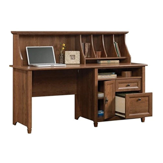
Computer Desk with Hutch
Edge Water Collection | 419401
Need help? Visit Sauder.com to view video assembly tips or chat with a live rep.
Prefer the phone? Call 1-800-523-3987.
Share your journey!
For all your
newfangled gadgetry.
NOTE: THIS INSTRUCTION
BOOKLET CONTAINS IMPORTANT
SAFETY INFORMATION.
PLEASE READ AND KEEP FOR
FUTURE REFERENCE.
English pg 1-34
Français pg 35-39
Español pg 40-44
Lot # 374148
08/18/15
Purchased: __________________
Be sure to give us a ring before
making any returns. 1-800-523-3987
Publicidad
Tabla de contenido

Manuales relacionados para Sauder Edge Water 419401


Resumen de contenidos para Sauder Edge Water 419401
- Página 1 Edge Water Collection | 419401 NOTE: THIS INSTRUCTION BOOKLET CONTAINS IMPORTANT SAFETY INFORMATION. Need help? Visit Sauder.com to view video assembly tips or chat with a live rep. PLEASE READ AND KEEP FOR FUTURE REFERENCE. Prefer the phone? Call 1-800-523-3987.
- Página 2 D484 DRAWER BOX FRONT (2) LARGE BACK (1) DRAWER FRONT (1) D485 LARGE DRAWER BOX FRONT (2) BACK (1) LARGE DRAWER FRONT (1) D713 DRAWER BOTTOM (2) DOOR (1) FRONT MOLDING (1) ADJUSTABLE SHELF (1) SHELF MOLDING (1) Page 2 419401 www.sauder.com/services...
-
Página 3: Part Identifi Cation
Part Identifi cation D484 D216 D713 D216 D484 D102 D485 D713 D485 D102 www.sauder.com/services 419401 Page 3... - Página 4 CONNECTOR - 2 FASTENER - 2 13H HINGE - 2 17K KNOB - 3 18K BACKPLATE - 1 DOOR STOP - 1 RUBBER SLEEVE - 4 NAIL - 61 CAM COVER - 20 METAL PIN - 15 Page 4 419401 www.sauder.com/services...
-
Página 5: Tabla De Contenido
SILVER 1-1/8" FLAT HEAD SCREW - 2 16S BLACK 1-7/8" PAN HEAD SCREW - 3 BLACK 7/8" LARGE HEAD SCREW - 6 30S BLACK 1-9/16" FLAT HEAD SCREW - 16 BLACK 1-1/8" MACHINE SCREW - 3 www.sauder.com/services 419401 Page 5... - Página 6 Assemble your unit on a carpeted fl oor or on the empty å carton to avoid scratching your unit or the fl oor. To begin assembly, push a SAUDER TWIST-LOCK® å FASTENER (10F) into the large holes in the MODESTY PANEL (G).
- Página 7 Arrow Arrow Arrow Hole Insert the metal end of the CAM DOWEL into the HIDDEN CAM. The arrow in the HIDDEN CAM must point toward the hole in the edge of the board. www.sauder.com/services 419401 Page 7...
- Página 8 Step 3 Turn eleven CAM SCREWS (8F) into the LEGS (M) and å SHELF MOLDING (X). Remember: Righty tighty. Lefty loosey. (11 used) Page 8 419401 www.sauder.com/services...
- Página 9 Tap two MOLDING CONNECTORS (17F) into the notches å in the TOP MOLDINGS (Z, AA, and BB). Use your hammer to tap the MOLDING CONNECTORS (17F) into the notches in the MOLDINGS. Flat end Flat end www.sauder.com/services 419401 Page 9...
- Página 10 HUTCH TOP (Q). Use nine BLACK 1-1/4" FLAT HEAD SCREWS (7S). NOTE: Do not overtighten the SCREWS into the TOP. å Do not overtighten the SCREWS (7S). BLACK 1-1/4" FLAT HEAD SCREW (9 used in this step) Unfi nished edge Page 10 419401 www.sauder.com/services...
- Página 11 Tighten Risk of damage or Arrow injury. HIDDEN CAMS must be completely Arrow Maximum tightened. HIDDEN 210 degrees CAMS that are not completely tightened may loosen, and parts may separate. To Minimum completely tighten: 190 degrees www.sauder.com/services 419401 Page 11...
- Página 12 Insert nine METAL PINS (1R) into the DIVIDERS (T). å Insert the METAL PIN (1R) in the short end of each å DIVIDER (T) into the holes in the HUTCH TOP (Q). (9 used) Curved edge Page 12 419401 www.sauder.com/services...
- Página 13 HUTCH UPRIGHT (P). Tighten four HIDDEN CAMS. Maximum Arrow 210 degrees NOTE: Be sure the METAL PINS in the DIVIDERS (T) insert å into the holes in the HUTCH SHELF. Minimum 190 degrees Finished edge www.sauder.com/services 419401 Page 13...
- Página 14 HUTCH LEFT END. Curved edge Surface with HIDDEN CAMS S u r f a c e H I D w i t h D E N o u t C A M Curved edge Page 14 419401 www.sauder.com/services...
- Página 15 HUTCH UPRIGHT (P). Use three BLACK 1-7/8" FLAT in a day. HEAD SCREWS (2S). Rounded edge S u r f a c r e h i t h o l e BLACK 1-7/8" FLAT HEAD SCREW (3 used in this step) www.sauder.com/services 419401 Page 15...
-
Página 16: Black 9/16" Large Head Screw
Cut-out f a c s u r n i s h U n fi Curved edge BLACK 9/16" LARGE HEAD SCREW These holes must line up over (3 used for the DIVIDERS) the HUTCH UPRIGHT (P). Page 16 419401 www.sauder.com/services... - Página 17 Fasten the FEET (CC) to the LEGS (M). Use three BLACK å 1-7/8" PAN HEAD SCREWS (16S). These surfaces should be even. These surfaces should be even. These surfaces should be even. Curved edge Curved edge BLACK 1-7/8" PAN HEAD SCREW (3 used in this step) www.sauder.com/services 419401 Page 17...
- Página 18 END (A) and the CABINET LEFTS (40CB) to the RIGHT UPRIGHT (C). Use eight GOLD 5/16" FLAT HEAD SCREWS (3S) through holes #1 and #3. Roller end GOLD 5/16" FLAT HEAD SCREW (8 used in this step) Roller end Finished edge Page 18 419401 www.sauder.com/services...
- Página 19 Fasten the MODESTY PANEL (G) to the LEFT END (B). å Tighten three HIDDEN CAMS. Maximum Arrow 210 degrees Minimum 190 degrees Notch S u r f a c H I D D E N i t h Edge with HIDDEN CAMS www.sauder.com/services 419401 Page 19...
- Página 20 Step 15 Carefully turn your Hutch assembly onto its back. å ® How to use the SAUDER TWIST-LOCK FASTENER Fasten the LEFT END (B) and MODESTY PANEL (G) 1. Insert the dowel end of the FASTENER into the hole of the å...
-
Página 21: Silver 1-1/8" Flat Head Screw
SILVER 1-1/8" FLAT HEAD SCREW (2 used for the TOP MOLDING) i t h f a c S u r D E N H I D BLACK 1-7/8" FLAT HEAD SCREW (2 used in this step) www.sauder.com/services 419401 Page 21... - Página 22 Fasten the SHELF MOLDING (X) to the SHELF (H). å Tighten two HIDDEN CAMS. Minimum 190 degrees Unfi nished surface S u r f a c H I D D E N i t h Notch Page 22 419401 www.sauder.com/services...
-
Página 23: Black 1-1/4" Flat Head Screw
Finished edge S u r f a c H I D D E N i t h These holes must be here. Surface with HIDDEN CAMS BLACK 1-7/8" FLAT HEAD SCREW (2 used in this step) www.sauder.com/services 419401 Page 23... - Página 24 ANGLE BRACKETS on the BOTTOM and into the FRONT MOLDING. Angled edge i t h o f a c S u r D E N H I D BLACK 9/16" LARGE HEAD SCREW (4 used in this step) Page 24 419401 www.sauder.com/services...
- Página 25 å the SHELF (H). NOTE: Perforations have been provided for access through the å BACK. Carefully cut out the holes needed. NAIL (28 used in this step) These holes must line up over the SHELF (H). www.sauder.com/services 419401 Page 25...
-
Página 26: Black 1/2" Flat Head Screw
Step 21 Fasten two HINGES (13H) to the DOOR (K). Use four å BLACK 1/2" FLAT HEAD SCREWS (11S). BLACK 1/2” FLAT HEAD SCREW (4 used in this step) Page 26 419401 www.sauder.com/services... - Página 27 Fasten a KNOB (17K) and BACKPLATE (18K) to the DOOR (K). å Use a BLACK 1-1/8" MACHINE SCREW (21S). Hinge See the next step for DOOR adjustments. å BLACK 1-1/8" MACHINE SCREW (1 used in this step) www.sauder.com/services 419401 Page 27...
- Página 28 To adjust the DOORS in or out (depth), loosen the mounting å screw one turn and move the DOORS in or out, as needed. Tighten the mounting screw after making adjustments. Mounting screw (depth) Adjusting screw (horizontal) (vertical adjustment) Page 28 419401 www.sauder.com/services...
-
Página 29: Black 1-9/16" Flat Head Screw
Repeat this step for the other drawer using the DRAWER SIDES (D216) and DRAWER BOX FRONTS (D484). å D102 BLACK 1-9/16" FLAT HEAD SCREW D485 (16 used in this step) D102 Groove Be sure the DRAWER BOTTOM inserts into the LARGE DRAWER BOX FRONT groove. D485 D102 D102 D485 D713 www.sauder.com/services 419401 Page 29... - Página 30 å BOX FRONTS (D484 and D485). Use six BLACK 7/8" LARGE HEAD SCREWS (17S). These holes must line up. D484 These holes must line up. BLACK 7/8" LARGE HEAD SCREW (6 used in this step) D485 Page 30 419401 www.sauder.com/services...
- Página 31 Repeat this step for the other drawer. å Roller end BLACK 1-1/8" MACHINE SCREW (2 used for the KNOBS) D102 Roller end D102 (4 screws per drawer) GOLD 5/16" FLAT HEAD SCREW (8 used in this step) www.sauder.com/services 419401 Page 31...
- Página 32 FILE RODS (8B), then press this FILE GLIDE over the LARGE LEFT DRAWER SIDE (D102). Insert the FILE RODS into the holes of your choice in the FILE GLIDES, depending on your fi le sizes. D102 D102 Page 32 419401 www.sauder.com/services...
- Página 33 Push a CAM COVER (13P) onto each visible HIDDEN CAM. å BLACK 1-7/8" FLAT HEAD SCREW (1 used into a stud in your wall) BLACK 9/16" LARGE HEAD SCREW (1 used into your unit) (20 used) To cover HIDDEN CAMS www.sauder.com/services 419401 Page 33...
- Página 34 This completes assembly. Clean with your favorite furniture polish or a damp cloth. Wipe dry. å And to celebrate, why not share your success story? 15 lbs. total 25 lbs. 20 lbs. 70 lbs. 10 lbs. 35 lbs. 25 lbs. 20 lbs. (4 used) Page 34 419401 www.sauder.com/services...
-
Página 35: Liste De Pièces
EXTRÉMITÉ DROITE ..........1 40CA ÉLÉMENT DROITE............2 pour future référence. EXTRÉMITÉ GAUCHE ..........1 40CB ÉLÉMENT GAUCHE ..........2 Pour contacter Sauder MONTANT DROIT ............1 40CC TIROIR DROIT ..............2 en ce qui concerne cet MONTANT GAUCHE ..........1 40CD TIROIR GAUCHE ............2 élément, faire référence... - Página 36 DE SURMEUBLE (P) au DESSUS DE SURMEUBLE (Q). Serrer Pour commencer l'assemblage, enfoncer une FIXATION quatre EXCENTRIQUES ESCAMOTABLES. TWIST-LOCK® SAUDER (10F) dans les gros trous dans le VOILE DE FOND (G). Attention: Risque des dégâts ou blessures. Les Excentriques Escamotables doivent être serrés à bloc. Les Excentriques Escamotables que ne sont pas serrées à...
- Página 37 FIXATIONS TWIST-LOCK®. Veiller à avoir des marges égales le long des quatre chants du Utilisation de la FIXATION TWIST-LOCK® SAUDER GRAND ARRIÈRE (I). Si besoin est, enfoncer sur les coins opposés 1. Insérer l'extrémité fi letée de la FIXATION dans le trou de la de l'élément pour s'assurer d'être «...
- Página 38 CÔTÉS DE GRAND TIROIR (D102). Utiliser quatre VIS TÊTE PLATE 40 mm NOIRES (30S). Répéter cette étape pour l'autre tiroir en utilisant les CÔTÉS DE TIROIR (D216) et les DEVANTS DE CAISSON DE TIROIR (D484). Page 38 419401 www.sauder.com/services...
- Página 39 Essuyer. GRAND TIROIR. Enfi ler une autre ARMATURE POUR DOSSIERS (3B) sur l'autre extrémité des GUIDES POUR DOSSIERS (8B) et appuyer cette ARMATURE POUR DOSSIERS sur le CÔTÉ GAUCHE DE GRAND TIROIR (D102). www.sauder.com/services 419401 Page 39...
-
Página 40: Escritorio De Computadora Con Organizador
EXTREMO IZQUIERDO ..........1 VARILLA DE ARCHIVERO ........2 pour future référence. PARAL DERECHO ............1 EXCÉNTRICO ESCONDIDO ......42 PARAL IZQUIERDO .............1 Pour contacter Sauder PASADOR DE EXCÉNTRICO ......31 PANEL SUPERIOR ............1 en ce qui concerne cet BIELA DE EXCÉNTRICO ........11 FONDO .................1 10F SUJETADOR TWIST-LOCK®... - Página 41 Para comenzar el ensamblaje, empuje un SUJETADOR TWIST-LOCK® Apriete cuatro EXCÉNTRICOS ESCONDIDOS. SAUDER (10F) dentro de los agujeros grandes del VELO DE FONDO (G). Precaución: Riesgo de daños o heridas. Los Excéntricos Escondidos deben apretarse completamente. Los Excéntricos Escondidos que PASO 2 no se aprieten completamente se afl...
- Página 42 SUJETADORES TWIST-LOCK®. Cuidadosamente gire su ensamble sobre el PANEL SUPERIOR (E) Cómo utilizar el SUJETADOR TWIST-LOCK® SAUDER y coloque el DORSO GRANDE (I) sobre la unidad. 1. Inserte el extremo con cabilla del SUJETADOR en el agujero de Los márgenes a lo largo de los cuatro bordes del DORSO...
- Página 43 Fije el otro FRENTE DE CAJÓN GRANDE (D485) a los LADOS DE CAJÓN GRANDE (D102). Utilice cuatro TORNILLOS NEGROS DE CABEZA PERDIDA de 40 mm (30S). Repita este paso para el otro cajón utilizando los LADOS DE CAJÓN (D216) y los FRENTES DE CAJÓN (D484). www.sauder.com/services 419401 Page 43...
- Página 44 Seque con un paño. DERECHO DE CAJÓN GRANDE (D87). Deslice otro CORRIMIENTO DE ARCHIVERO (3B) sobre el otro extremo de las VARILLAS DE ARCHIVERO (8B) y presione este CORRIMIENTO DE ARCHIVERO sobre el LADO IZQUIERDO DE CAJÓN GRANDE (D102). Page 44 419401 www.sauder.com/services...
- Página 45 à Les téléviseurs peuvent être particulièrement un téléviseur. cet eff et. lourds. De plus, le poids et l’emplacement du tube image ont tendance à rendre les téléviseurs instables et enclins à tomber vers l’ a vant. www.sauder.com/services 419401 Page 45...
- Página 46 Además, el peso y la ubicación del tubo de imagen tienden a causar la inestabilidad de televisores y propensa a volcarse hacia adelante. Page 46 419401 www.sauder.com/services...
-
Página 47: Garantie Limitée De 5 Ans
GARANTIE LIMITÉE DE 5 ANS 1. Sauder Woodworking Co. (Sauder®) off re une couverture de garantie limitée à l’ a cheteur 4. La présente garantie ne s’ a pplique qu’ a ux défauts garantis qui se produisent pour initial du présent produit pendant une période de cinq ans à... - Página 48 Dear Valued Customer: So, how did it go? Thanks so much for choosing Sauder® furniture. I hope the Set a world record for speed? purchase and assembly process was a positive experience Feeling good about yourself? and you feel good about the furniture you just built. If you Nice.