
Manuales relacionados para Amprobe SOLAR-600


Resumen de contenidos para Amprobe SOLAR-600
- Página 1 SOLAR-600 Solar Analyzer Users Manual • Mode d’emploi • Bedienungshandbuch • Manual d’Uso • Manual de uso...
- Página 3 SOLAR-600 Solar Analyzer Users Manual May 2013, Rev.2 ©2013 Amprobe wTest Tools. All rights reserved. Printed in Taiwan...
- Página 4 Limited Warranty and Limitation of Liability Your Amprobe product will be free from defects in material and workmanship for 1 year from the date of purchase. This warranty does not cover fuses, disposable batteries or damage from accident, neglect, misuse, alteration, contamination, or abnormal conditions of operation or handling. Resellers are not authorized to extend any other warranty on Amprobe’s behalf.
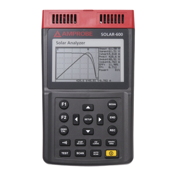
- Página 5 SOLAR-600 Solar Analyzer A) Front Panel...
- Página 6 SOLAR-600 Solar Analyzer Button F1Button: (Reserved) In the SETUP menu, press button to select previous item F2 Button: (Reserved) Button ZERO CAL In the SETUP menu, press button to select next item Zero calibration of voltage and current. Connect (short) the two Kelvin clips together and press this button.
- Página 7 SOLAR-600 Solar Analyzer B) Rear Panel 1) Communication Window To connect Solar Analyzer with PC via USB cable 2) Stand 3) Battery Cover 4) Screw of battery cover 5) AC to DC adaptor input C) TOP Panel (Connectors) 1) V+ Terminal...
-
Página 8: Tabla De Contenido
SOLAR-600 Solar Analyzer CONTENTS SYMBOLS, WARNINGS AND PREPARATION ............2 UNPACKING AND INSPECTION ................3 INTRODUCTION ....................4 OPERATION ......................7 Selected Condition of Auto Scan, Manual Scan, or Test ........ 8 Connecting Diagram ..................10 Auto Scan ......................11 Manual Scan ..................... -
Página 9: Symbols, Warnings And Preparation
SYMBOLS, WARNINGS AND PREPARATION Symbols and Warnings: Please read the statement thoroughly to prevent injury or loss of life, and prevent damage to this product. Caution: 1. The ventilation openings on the unit should not be blocked. � 2. Please pay attention to polarity of DC input, follow the polarity info by the input jack. -
Página 10: Unpacking And Inspection
UNPACKING AND INSPECTION Your shipping carton should include: SOLAR 600 Solar Analyzer Carrying Bag Users Manual AC Adaptor RS232C (to USB Bridge) Cable Rechargeable Lithium Battery Pack Software CD Software Manual Kelvin Clips (12A max, 1 pair) If any of the items are damaged or missing, return the complete package to the place of purchase for an exchange. -
Página 11: Introduction
INTRODUCTION The SOLAR-600 can be used in Quality Control for Production Line, Warehouse or Site of Installation. Manufacturers of solar panels can test the characteristics for quality control purpose in the production line. Due to the advantage of portability of the unit, quality inspectors can randomly pick samples of solar panels and test them in the warehouse to assure quality before shipment. - Página 12 Example B: Maintenance of Solar Panels Abnormal I-V Curve (Cells at the corner of solar panel are defected)
- Página 13 Abnormal I-V Curve (defected cells scattered over the solar panel) The technicians or maintenance engineers can store the characteristics data of solar panels in the beginning. And compare the characteristics data in the weekly, monthly or yearly maintenance. If the characteristics of any solar panels are different from the previous data, technicians or maintenance engineers can further identify the problems of solar panels.
-
Página 14: Operation
OPERATION WARNING! � when users see “Overheated” warning shown in LCD 1. Users must wait during this “Overheated: cooling” period before they start next simulation. 2. And if users would like to turn the unit off, they must wait for another 3 min. -
Página 15: Selected Condition Of Auto Scan, Manual Scan, Or Test
Selected Condition of Auto Scan, Manual Scan, or Test Users should first select AUTO SCAN ( ) to obtain a general idea of characteristics of a solar panel. 1. Press button to turn on the Analyzer. Properly connect the pair of Kelvin clips to the solar panel and the Analyzer. - Página 16 3. Press button to start MANUAL SCAN. After the scanning is finished, the result will come out like below. If users are interested in a specific point of test current, users can enter the current value for a Single Test Point. Press TEST ( ) to test the characteristics at the current.
-
Página 17: Connecting Diagram
Connecting Diagram Kelvin Clip Connecting Diagram Alligator Clip Connecting Diagram... -
Página 18: Auto Scan
Auto Scan 1. Press button to turn on the Analyzer. 2. Properly connect the pair of Kelvin clips to the solar panel and the Analyzer. The red Kelvin clip is for positive pole and the black Kelvin clip for negative pole. (refer to above Connecting Diagram). 3. -
Página 19: Manual Scan
Manual Scan 1. Press button to turn on the Analyzer. 2. Properly connect the pair of Kelvin clips to the solar panel and the Analyzer. The red Kelvin clip is for positive pole and the black Kelvin clip for negative pole. 3. -
Página 20: Single Point Test
Single Point Test 1. Press button to turn on the Analyzer. 2. Properly connect the pair of Kelvin clips to the solar panel and the Analyzer. The red Kelvin clip is for positive pole and the black Kelvin clip for negative pole. 3. -
Página 21: Data Logging
Data Logging Users can perform data logging to record the characteristics of solar power over a period of time (e.g. record data every 60 minutes). 1. Set the sampling time in the SETUP menu. 2. Press the REC button, then AUTO SCAN will be performed and data will be recorded. -
Página 22: Zero Calibration
Zero Calibration Calibration of voltage and current zero would improve the accuracy of the instrument before usage. Connect (short) the two Kelvin clips together and press and hold the button. A message of “ZERO CAL…” is shown in LCD. Release the button when the message disappears. -
Página 23: Clear Recorded Testing Data
Clear recorded testing data Users can clear the recorded testing data in the Analyzer. The procedures of deleting saved data: 1. Keep pressing (REC) button and turn on the Analyzer (i.e. press button ) at the same time. 2. After turning on the Analyzer, all the data recorded in the Analyzer (memory) will be deleted. - Página 24 (1) Time delay before scan. This delay allows light source to illuminate the solar panel before scan stars. (2) Sampling time of data logging (0 to 99 minutes) (3) Current Range of Scan begin. The beginning value of current for scan to start. (4) Current Range of Scan end.
-
Página 25: Specification
SPECIFICATION Electrical Specifications (23°C ±5°C, Four-wire Measurement) DC Voltage Measurement Range Resolution Accuracy 0 ~ 10 V 0.001 V ± 1 % ± (1 % of Vopen ± 0.1 V) 10 ~ 60 V 0.01 V ± 1 % ± (1 % of Vopen ± 0.1 V) Vopen: open circuit voltage of solar cell or module. -
Página 26: Electrical Specification
Electrical Specifications (23°C ±5°C, Four-wire Measurement) Battery Type Rechargeable Lithium Battery, 11.1Vdc, 3400mAh Battery Life 400 times of linear scan from 60V to 0V and 0A to 12A Data Logging 99 records Memory Size AC Adaptor AC 110V or 220V input DC 15V / 1~3A output Dimension 257(L) x 155(W) x 57(H) mm (10.12 x 6.1 x 2.24 inch) -
Página 27: Maintenance And Repair
The charging circuit built-in is designed only for the lithium battery included. ® Only AMPROBE genuine part and Lithium battery pack can be allowed to use on your SOLAR 600. Incorrect battery type and specification could cause damage or hazard on instrument and user. -
Página 28: Fuse Replacement
Fuse Replacement When the voltage can not be measured (Vnow = 0V) after properly connecting the Analyzer and the solar panel, please check the fuse. If the fuse is damaged (burned), please replace a new fuse by following the procedures: 1. -
Página 29: Maintenance & Cleaning
WARNING! � After removing the bottom cover, please do not touch the parts on the circuit board, especially the communication LED. Or the communication function will fail. Maintenance & Cleaning 1. Servicing not covered in this manual should only be performed by qualified personnel. -
Página 30: Pc Connection, Software Installation And Operation
PC Connection, Software Installation And Operation INTROODUCTION Operating Environment • The Software (Application program) should be installed in the operation system of Microsoft Windows Vista / XP / 2000 (SP3). • USB driver program should be installed (the Software will install it automatically). -
Página 31: Software Installation 24
SOFTWARE INSTALLATION Install Software Execute Install.bat (which is in the software disc) to enter the procedures of installing the Software. Please follow the instructions to install the Software. During the installation, the USB driver program and the Analyzer Software will be installed automatically. -
Página 32: Software Operation
SOFTWARE OPERATION Start Executing Program Click Start -> All Programs -> Solar Module Analyzer 12A, choose “Solar Module Analyzer 12A” or click the shortcut to start executing the Software. Working Window before Communication Communication After clicking “Communication” on the display, the Software will check if the Analyzer is connecting with the PC. -
Página 33: Working Window After Communication
Working Window after Communication There are four main parts in this window: 1. Communication. 2. Tool bar. 3. Information, Parameters and Overall. 4. Message. Communication To get the information of the Analyzer, first make sure the communication between the Analyzer and the PC work well. If the communication with the Analyzer is stopped during operation, the PC will display a warning –... -
Página 34: Tool Bar
Tool Bar New Recording : Start new recording. Open File : Open and read a file. Save File : Save all the present samples to a file named *.sma_12A Expor t: If users click the top of this function, then all the present records will be exported to a file (in the same format as the last one selected by users) which can be read in EXCEL. - Página 35 Clear Records : The recording data of the Analyzer will be cleared. Auto Scan : Let the Analyzer perform “Auto Scan” function, then get the measurement data and include them in the sample record of the PC. Cycle Scan : Users can set up a Cycle Time, and then the Software will perform “Auto Scan”...
-
Página 36: Information, Parameter, Overall
Information, Parameter, Overall A.1 Information Display the curves and data of the measurements. Display the starting time of recording, curves and data. Select display modes of curves: 1. IV: only display IV curve (such like the read line). 2. P: only display W (power) curve (such like the green curve). 3. - Página 37 1. V (5.659V) in red for Y axis; 2. I (767mA) in white for X axis; 3. W (4.342W) in green. Bedside moving the mouse, users also can use the t and u buttons of the PC keyboard to move the scale. (but it will work only when the cursor of the mouse is located inside the curve.) BEGIN, END, SCAN: When the cursor of the mouse is located inside the waveform, users can...
- Página 38 B. IParameter Users can set up the parameters of the Analyzer by typing in values and press “Apply” of each parameter. Users can press “Apply All” button to reset all the parameters of the Analyzer. Or press “Load” button to download the present parameters of the Analyzer.
- Página 39 Overall Trend: Various figures are displayed in different colors. 1.Mouse the mouse to a certain point of one curve, then this point will become the “Present Sample”. 2.Another way is to use the direction keys of the PC keyboard. Press t button to review last sample;...
- Página 41 SOLAR-600 Analyseur solaire Mode d’emploi Mai 2013, rév.2 ©2013 Amprobe Test Tools. Tous droits réservés. Imprimé à Taïwan.
- Página 42 Test Tools pour être échangé contre un produit identique ou similaire. ® Consultez la section « Where to Buy » sur le site www.amprobe.com pour obtenir la liste des distributeurs dans votre région. Au Canada et aux Etats-Unis, les appareils devant être remplacés ou réparés sous garantie peuvent également être envoyés dans un centre de services Amprobe...
- Página 43 SOLAR-600 Analyseur solaire A) Face avant...
- Página 44 Analyseur solaire SOLAR-600 Bouton Bouton F1 : (Réservé) Dans le menu SETUP, appuyer sur le Bouton F2 : (Réservé) bouton pour sélectionner l’élément précédent ZERO CAL Bouton Calibrage du zéro de la tension et du Dans le menu SETUP, appuyer sur le courant.
- Página 45 Analyseur solaire SOLAR-600 B) Face arrière 1) Fenêtre de communication Pour relier l’analyseur solaire à un PC par câble USB 2) Béquille 3) Couvercle de batterie 4) Vis du couvercle de batterie 5) Entrée du convertisseur de courant alternatif à...
- Página 46 Analyseur solaire SOLAR-600 TABLE DES MATIERES SYMBOLES, MISES EN GARDE ET PREPARATION..........2 DEBALLAGE ET INSPECTION ................3 INTRODUCTION ....................4 FONCTIONNEMENT ....................7 Etat sélectionné de l’analyse automatique, de l’analyse manuelle ou d’un test ...................... 8 Schéma de connexion ..................10 Analyse automatique ..................
-
Página 47: Symboles, Mises En Garde Et Preparation
SYMBOLES, MISES EN GARDE ET PREPARATION Symboles et avertissements : Veuillez lire soigneusement cette déclaration pour ne pas endommager cet appareil et éviter les blessures, voire les décès. Attention : 1. Les ouïes de ventilation sur l’appareil ne doivent pas être bloquées �... -
Página 48: Deballage Et Inspection
DéBALLAGE ET INSPECTION Le carton d’emballage doit inclure les éléments suivants : analyseur solaire SOLAR 600 sacoche de transport Mode d’emploi adaptateur secteur câble de conversion RS232C (à USB ) bloc-batterie rechargeable au lithium CD de logiciel manuel de logiciel paire de pinces Kelvin (12 A max, 1 paire) Si l’un de ces éléments est endommagé... -
Página 49: Introduction
INTRODUCTION Le SOLAR-600 peut être utilisé pour le contrôle de la qualité sur les chaînes de production, les entrepôts ou les sites d’installation. Les fabricants de panneaux solaires peuvent tester les caractéristiques du contrôle qualité lié à la chaîne de production. La portabilité de l’appareil permet aux inspecteurs qualité... - Página 50 Exemple B : Entretien des panneaux solaires Courbe I-V anormale (les cellules dans le coin du panneau solaire sont défectueuses)
- Página 51 Courbe I-V anormale (présence de cellules défectueuses disséminées sur le panneau solaire) Les techniciens ou les ingénieurs de maintenance peuvent archiver les données caractéristiques des panneaux solaires au commencement, puis comparer ces caractéristiques lors des tâches de maintenance hebdomadaires, mensuelles et annuelles.
-
Página 52: Fonctionnement
FONCTIONNEMENT AVERTISSEMENT ! � Lorsque le message « Overheated » (Surchauffe) apparaît sur l’écran LCD : 1. Les utilisateurs doivent patienter pendant cette période « Overheated: cooling » (Surchauffe : refroidissement en cours) avant de démarrer la simulation suivante. 2. Si les utilisateurs souhaitent éteindre leur appareil, ils doivent attendre encore 3 mn (au moins) que le ventilateur refroidisse les composants internes. -
Página 53: Etat Sélectionné De L'analyse Automatique, De L'analyse Manuelle Ou D'un Test
Etat sélectionné de l’analyse automatique, de l’analyse manuelle ou d’un test Les utilisateurs doivent d’abord sélectionner AUTO SCAN ( ) pour obtenir une vision globale des caractéristiques du panneau solaire. 1. Appuyez sur le bouton pour activer l’analyseur. Reliez correctement la paire de pinces Kelvin au panneau solaire et à l’analyseur. - Página 54 3. Appuyez sur le bouton pour lancer l’analyse manuelle MANUAL SCAN. Une fois l’analyse terminée, le résultat s’affiche comme suit. Si les utilisateurs sont intéressés par un point de test spécifique, ils peuvent entrer la valeur active pour un point de test unique. Appuyez sur TEST ( ) pour tester les caractéristiques au niveau du courant.
-
Página 55: Schéma De Connexion
Schéma de connexion Schéma de connexion des pinces Kelvin Schéma de connexion des pinces crocodiles... -
Página 56: Analyse Automatique
Analyse automatique 1. Appuyez sur le bouton pour activer l’analyseur. 2. Reliez correctement la paire de pinces Kelvin au panneau solaire et à l’analyseur. La pince Kelvin rouge correspond au pôle positif et la pince Kelvin noire au pôle négatif. (Reportez-vous au schéma de connexion ci-dessus.) 3. -
Página 57: Analyse Manuelle
Analyse manuelle 1. Appuyez sur le bouton pour allumer l’analyseur. 2. Reliez correctement la paire de pinces Kelvin au panneau solaire et à l’analyseur. La pince Kelvin rouge correspond au pôle positif et la pince Kelvin noire au pôle négatif. 3. -
Página 58: Test En Un Point
Test en un point 1. Appuyez sur le bouton pour activer l’analyseur. 2. Reliez correctement la paire de pinces Kelvin au panneau solaire et à l’analyseur. La pince Kelvin rouge correspond au pôle positif et la pince Kelvin noire au pôle négatif. 3. -
Página 59: Centrale De Mesure
Centrale de mesure Les utilisateurs peuvent acquérir des données pour enregistrer les caractéristiques de l’alimentation solaire sur une période de temps (p. ex. enregistrer les données toutes les 60 minutes). 1. Réglez le temps d’échantillonnage dans le menu SETUP. 2. Appuyez sur le bouton REC : l’analyse automatique AUTO SCAN est exécutée et les données sont enregistrées. -
Página 60: Calibrage Du Zéro
Calibrage du zéro Un calibrage du zéro de tension et de courant améliore la précision de l’instrument avant l’emploi. Reliez (mettre en court-circuit) les deux pinces Kelvin entre elle en maintenant le bouton enfoncé. Un message « ZERO CAL… » apparaît sur l’affichage LCD. -
Página 61: Effacer Les Données De Test Enregistrées
Effacer les données de test enregistrées Les utilisateurs peuvent effacer les données de test enregistrées dans l’analyseur. Procédures de suppression des données enregistrées : 1. Maintenez le bouton (REC) enfoncé et mettez l’analyseur sous tension en même temps (appuyez sur le bouton 2. - Página 62 (1) Time delay before scan (Temporisation avant l’analyse) Cette temporisation permet à la source lumineuse d’illuminer le panneau solaire avant le lancement de l’analyse. (2) Sampling time of data logging (Durée d’échantillonnage d’acquisition des données (0 à 99 minutes)) (3) Current Range of Scan begin (La gamme d’analyse commence) La valeur de courant initiale pour lancer l’analyse.
-
Página 63: Caracteristiques
CARACTERISTIQUES Caractéristiques électriques (23 °C ± 5 °C, mesure à quatre fils) Mesure de tension continue. Gamme Résolution Précision 0 V à 10 V 0,001 V ± 1 % ± (1 % de Vopen ± 0,1 V) 10 V à 60 V 0,01 V ±... - Página 64 Caractéristiques électriques (23 °C ± 5 °C, mesure à quatre fils) Type de batterie Batterie rechargeable au lithium, 11,1 V c.c. 3400 mAh Autonomie 400 heures d’analyse linéaire de 60 V à 0 V et de 0 A à 12 A Centrale de 99 enregistrements mesure...
-
Página 65: Entretien Et Reparation
Le circuit de mise en charge intégré est spécialement conçu pour la batterie au lithium incluse. ® Le bloc-batterie AMPROBE authentique au lithium est la seule batterie autorisée pour le SOLAR 600. Une spécification et un type de batterie incorrect pourraient endommager l’instrument ou mettre en danger l’utilisateur. -
Página 66: Changement De Fusible
Changement de fusible Si vous ne pouvez pas mesurer la tension (Vnow = 0 V) après avoir correctement relié l’analyseur et le panneau solaire, vérifiez le fusible. Si le fusible est endommagé (grillé), remplacez-le en utilisant l’une des procédures suivantes : 1. -
Página 67: Entretien Et Nettoyage
AVERTISSEMENT ! � Ne pas toucher aux pièces du circuit imprimé, surtout à la DEL de communication, après avoir retiré la face inférieure du boîtier. Sinon la fonction de communication ne fonctionne pas. Entretien et nettoyage 1. Les interventions non traitées dans ce manuel ne doivent être effectuées que par un personnel qualifié. -
Página 68: Connexion Au Pc, Installation Et Utilisation Du Logiciel
Connexion au PC, installation et utilisation du logiciel INTRODUCTION Environnement de fonctionnement • Le logiciel (programme d’application) doit être installé dans le système d’exploitation Microsoft Windows Vista/ XP / 2000 (SP3). • Le programme du pilote USB doit être installé (le programme d’application est installé... -
Página 69: Installation Du Logiciel
INSTALLATION DU LOGICIEL Installer le logiciel Exécutez le fichier Install.bat (qui se trouve sur le disque du logiciel) pour procéder aux étapes d’installation du logiciel. Suivez les instructions pour installer le logiciel. Pendant l’installation, le programme du pilote USB et le logiciel de l’analyseur sera installé... -
Página 70: Utilisation Du Logiciel
UTILISATION DU LOGICIEL Démarrer l’exécution du programme Cliquez sur Démarrer -> Programmes -> Analyseur de module solaire 12A. Choisissez « Analyseur de module solaire 12A » ou cliquez sur le raccourci pour démarrer le logiciel. Fenêtre de travail avant la communication Communication Quand l’utilisateur clique sur «... -
Página 71: Fenêtre De Travail Après La Communication
Fenêtre de travail après la communication Cette fenêtre contient quatre éléments : 1. Communication. 2. Barre d’outils. 3. Onglets Information, Parameter, Overall (Informations, Paramètre, Tendance globale). 4. Message. Communication Pour obtenir des informations sur l’analyseur, la communication entre l’analyseur et le PC doit être établie. Si la communication avec l’analyseur s’est arrêtée en cours, le PC affiche un avertissement «... -
Página 72: Barre D'outils
Barre d’outils New Recording : Lance un nouvel enregistrement. Open File : Ouvre et lit un fichier. Save File : Enregistre tous les échantillons actuels dans un fichier nommé *.sma_12A. Export : Si l’utilisateur clique en haut de cette fonction, tous les enregistrements présents sont exportés vers un fichier (dans le format sélectionné... - Página 73 Clear Records : Les données d’enregistrement de l’analyseur sont alors supprimées. Auto Scan : Laissez l’analyseur effectuer une « Auto Scan » (analyse automatique) et récupérez les résultats pour les inclure à l’enregistrement d’échantillon du PC. Cycle Scan : Les utilisateurs peuvent configurer une durée cyclique pour que le logiciel effectue une fonction «...
-
Página 74: Informations, Paramètre, Tendance Globale
Informations, Paramètre, Tendance globale A.1 Information Affiche les courbes et les données des mesures. Affiche l’heure de début de l’enregistrement des courbes et des données. Sélectionner les modes d’affichage des courbes : 1. IV : n’affiche que la courbe IV (la ligne de lecture par exemple). 2. - Página 75 (ici les unités des axes Y et X sont V:I) 1. V (5659 V) en rouge pour l’axe Y ; 2. I (767 mA) en blanc pour l’axe X ; 3. W (4342 W) en vert. En plus de la souris, les utilisateurs peuvent également utiliser les boutons t et u du clavier de l'ordinateur pour déplacer l'échelle.
- Página 76 B. Parameter Les utilisateurs peuvent configurer les paramètres de l’analyseur en entrant leurs valeurs et en appuyant sur « Apply » (Appliquer) pour chacun d’eux. Les utilisateurs peuvent appuyer sur le bouton « Apply All » (Tout appliquer) pour rétablir tous les paramètres de l’analyseur. Vous pouvez également appuyer sur «...
- Página 77 Tendance globale : Les diverses figures sont affichées en différentes couleurs. 1. Amenez la souris en un point de la courbe : ce point devient alors « l’échantillon actuel » (Present Sample). 2. Une autre méthode consiste à utiliser les touches de direction du clavier de l’ordinateur.
- Página 79 SOLAR-600 Solar-Analyzer Bedienungshandbuch Mai 2013, Rev.2 ©2013 Amprobe Test Tools. Alle Rechte vorbehalten. Gedruckt in Taiwan.
- Página 80 Beschränkte Gewährleistung und Haftungsbeschränkung Es wird gewährleistet, dass dieses Amprobe-Produkt für die Dauer von einem Jahr ab dem Kaufdatum frei von Material- und Fertigungsdefekten ist. Diese Gewährleistung erstreckt sich nicht auf Sicherungen, Einwegbatterien oder Schäden durch Unfälle, Nachlässigkeit, Missbrauch, Änderungen oder abnormale Betriebsbedingungen bzw. unsachgemäße Handhabung. Die Garantieverpflichtung von Amprobe beschränkt sich darauf, dass Amprobe nach eigenem...
- Página 81 SOLAR-600 Solar-Analyzer A) Vorderseite...
- Página 82 SOLAR-600 Solar-Analyzer Taste F1-Taste: (reserviert) Im SETUP-Menü die Taste drücken, um das vorherige Element auszuwählen. F2-Taste: (reserviert) Taste ZERO CAL Im SETUP-Menü die Taste drücken, um Null-Kalibrierung von Spannung und das nächste Element auszuwählen. Stromstärke. Die zwei Kelvin-Klemmen verbinden (kurzschließen) und diese Taste Taste drücken.
- Página 83 SOLAR-600 Solar-Analyzer B) Rückseite 1) Kommunikationsfenster Zum Anschließen des Solar- Analyzer über USB-Kabel an einen PC. 2) Ständer 3) Batterieabdeckung 4) Schraube für Batterieabdeckung 5) Wechselstrom-/Gleichstrom- Adaptereingang C) Anschlüsse oben am Gerät 1) V+ Anschluss 2) I+ Anschluss 3) V- Anschluss...
- Página 84 SOLAR-600 Solar-Analyzer INHALT SYMBOLE, WARNUNGEN UND VORBEREITUNG ..........2 AUSPACKEN UND ÜBERPRÜFEN ................3 EINFÜHRUNG ......................4 BEDIENUNG ......................7 Ausgewählte Bedingung von Auto Scan, Manual Scan bzw. Test ....8 Anschlussdiagramm ..................10 Auto Scan ......................11 Manual Scan ..................... 12 Einzelpunkttest ....................
-
Página 85: Symbole, Warnungen Und Vorbereitung
SYMBOLE, WARNUNGEN UND VORBEREITUNG Symbole und Warnungen: Bitte diese Erklärungen sorgfältig durchlesen, um Verletzung oder Tod und Beschädigung dieses Produkts zu vermeiden. Vorsicht: 1. Die Lüftungsöffnungen am Gerät dürfen nicht blockiert werden. � 2. Die Polaritätsinformationen an der Eingangsbuchse befolgen und die Polarität des Gleichspannungseingangs beachten. -
Página 86: Auspacken Und Überprüfen
AUSPACKEN UND ÜBERPRÜFEN Der Verpackungskarton sollte Folgendes enthalten: SOLAR 600 Solar-Analyzer Tragetasche Bedienungshandbuch Netzadapter RS232C-Kabel (zu USB-Bridge) Wiederaufladbares Lithium-Batteriepack Software-CD Softwarehandbuch Kelvin-Klemmen (max. 12 A, 1 Paar) Wenn einer dieser Artikel beschädigt ist oder fehlt, die gesamte Lieferung zwecks Ersatz an die Verkaufsstelle zurücksenden. MERKMALE •... -
Página 87: Einführung
EINFÜHRUNG Der SOLAR-600 kann in der Qualitätskontrolle von Fertigungsstraßen, Lagerhäusern oder Anlageinstallationen verwendet werden. Hersteller von Solarkollektoren können die Eigenschaften für Qualitätskontrollzwecke in der Fertigungsstraße testen. Dank der Portabilität des Geräts können Qualitätsprüfer stichprobenartig Solarkollektoren prüfen und diese im Lagerhaus testen, um die Qualität vor dem Versand zu bestätigen. - Página 88 Beispiel B: Wartung von Solarkollektoren Abnormale I-V-Kennlinie (Zellen in der Ecke des Solarkollektors sind defekt)
- Página 89 Abnormale I-V-Kennlinie (Defekte Zellen sind über den Solarkollektor verteilt) Die Techniker oder Wartungsingenieure können die Eigenschaftsdaten von Solarkollektoren zu Beginn speichern. Die Eigenschaftsdaten können dann bei wöchentlichen, monatlichen bzw. jährlichen Wartungsarbeiten verglichen werden. Wenn die Eigenschaften eines Solarkollektors von den früheren Daten abweichen, können Techniker oder Wartungsingenieure die Probleme des Solarkollektors weiter identifizieren.
-
Página 90: Bedienung
BEDIENUNG WARNUNG! � Wenn auf der LCD „Overheated“ (Überhitzt) angezeigt wird: 1. Muss der Benutzer die Periode „Overheated: cooling“ (Überhitzt: Kühlung) abwarten, bevor er die nächste Simulation startet. 2. Falls der Benutzer das Gerät ausschalten möchte, muss er (mindestens) 3 weitere Minuten abwarten, damit der Ventilator die internen Komponenten abkühlen kann. -
Página 91: Ausgewählte Bedingung Von Auto Scan, Manual Scan Bzw. Test
Ausgewählte Bedingung von Auto Scan, Manual Scan bzw. Test Auto Scan Benutzer sollten zuerst AUTO SCAN ( ) auswählen, um eine Übersicht über die Eigenschaften eines Solarkollektors zu erhalten. 1. Die Taste drücken, um den Analyzer einzuschalten. Das Paar von Kelvin-Klemmen ordnungsgemäß an den Solarkollektor und an den Analyzer anschließen. - Página 92 3. Die Taste drücken, um MANUAL SCAN zu starten. Nach Abschluss der Scan-Funktion wird das Ergebnis wie unten angezeigt. Wenn ein bestimmter Punkt von Teststrom von Interesse ist, kann der Stromwert für einen Einzeltestpunkt eingegeben werden. TEST ( drücken, um die Eigenschaften am Strom zu testen. 1.
-
Página 93: Anschlussdiagramm
Anschlussdiagramm Kelvin-Klemme – Anschlussdiagramm Krokodilklemme – Anschlussdiagramm... -
Página 94: Auto Scan
Auto Scan 1. Die Taste drücken, um den Analyzer einzuschalten. 2. Das Paar von Kelvin-Klemmen ordnungsgemäß an den Solarkollektor und an den Analyzer anschließen. Die rote Kelvin-Klemme ist für den Pluspol konzipiert und die schwarze Kelvin-Klemme für den Minuspol. (Siehe das obige Anschlussdiagramm). 3. -
Página 95: Manual Scan
Manual Scan 1. Die Taste drücken, um den Analyzer einzuschalten. 2. Das Paar von Kelvin-Klemmen ordnungsgemäß an den Solarkollektor und an den Analyzer anschließen. Die rote Kelvin-Klemme ist für den Pluspol konzipiert und die schwarze Kelvin-Klemme für den Minuspol. 3. Die Taste drücken, um das SETUP-Menü... -
Página 96: Einzelpunkttest
Einzelpunkttest 1. Die Taste drücken, um den Analyzer einzuschalten. 2. Das Paar von Kelvin-Klemmen ordnungsgemäß an den Solarkollektor und an den Analyzer anschließen. Die rote Kelvin-Klemme ist für den Pluspol konzipiert und die schwarze Kelvin-Klemme für den Minuspol. 3. Die Taste drücken, um das SETUP-Menü... -
Página 97: Datenaufzeichnung
Datenaufzeichnung Benutzer können Datenaufzeichnungen durchführen, um die Eigenschaften der Solarenergie über eine Zeitdauer aufzuzeichnen (z. B. alle 60 Minuten). 1. Die Abtastzeit kann im SETUP-Menü festgelegt werden. 2. Die Taste REC drücken, sodass AUTO SCAN ausgeführt wird und Daten aufgezeichnet werden. Im obigen Beispiel werden alle 60 Minuten Daten erfasst. -
Página 98: Null-Kalibrierung
Null-Kalibrierung Kalibrierung von Spannung- und Stromstärke-Null vor Gebrauch verbessert die Genauigkeit des Messgeräts. Die zwei Kelvin-Klemmen verbinden (kurzschließen) und die Taste drücken und gedrückt halten. Die LCD zeigt die Meldung ZERO CAL… (Null-Kalibrierung) an. Die Taste freigeben, wenn die Meldung ausgeblendet wird. Regelmäßige Null-Kalibrierung bewahrt die Genauigkeit des Messgeräts. -
Página 99: Aufgezeichnete Testdaten Löschen
Aufgezeichnete Testdaten löschen Benutzer können die im Analyzer aufgezeichneten Testdaten löschen. Verfahren zum Löschen gespeicherter Daten: 1. Die Taste (REC) gedrückt halten und gleichzeitig den Analyzer einschalten (d. h. die Taste drücken). 2. Nach dem Einschalten des Analyzer werden alle im Speicher des Geräts gespeicherten Daten gelöscht. - Página 100 (1) Time delay before Scan (Zeitverzögerung vor Scan) Diese Verzögerung ermöglicht es der Lichtquelle, vor dem Start des Scans den Solarkollektor zu beleuchten. (2) Sampling Time of Data Logging (Abtastzeit für Datenaufzeichnung (0 bis 99 Minuten)) (3) Current Range of Scan begin (Strombereich von Scan-Beginn) Der Anfangswert von Strom, bei dem der Scan beginnt.
-
Página 101: Technische Daten
TECHNISCHE DATEN Elektrische Spezifikationen (23 °C ± 5 °C, Vierdrahtmessung) Gleichspannungsmessung Bereich Auflösung Genauigkeit 0 V ~ 10 V 0,001 V ± 1 % ± (1 % von Vopen ± 0,1 V) 10 V ~ 60 V 0,01 V ± 1 % ± (1 % von Vopen ± 0,1 V) Vopen: Leerlaufspannung von Solarzelle oder -modul. - Página 102 Elektrische Spezifikationen (23 °C ± 5 °C, Vierdrahtmessung) Batterietyp Wiederaufladbares Lithium-Batteriepack, 11,1 V DC, 3400 mAh Batterielebensdauer 400 Mal Linear-Scan von 60 V bis 0 V und 0 A bis 12 A Datenaufzeichnung 99 Datensätze Speichergröße Netzadapter Wechselspannung 110 V oder 220 V Eingang Gleichspannung 15 V / 1 A ~ 3 A Ausgang Abmessungen 257 (L) x 155 (B) x 57 (H) mm...
-
Página 103: Wartung Und Reparatur
Benutzer beim Händler eine neue Lithium-Batterie kaufen. Der integrierte Ladeschaltkreis ist ausschließlich für die gelieferte Lithium-Batterie konzipiert. ® Es sind nur authentische AMPROBE -Teile (einschl. Lithium-Batteriepack) für den Gebrauch im SOLAR 600 zulässig. Ein abweichender Batterietyp bzw. abweichende Spezifikationen können Beschädigung des Messgeräts oder Gefahr für den Benutzer verursachen. -
Página 104: Auswechseln Der Sicherung
Auswechseln der Sicherung Wenn der Analyzer und der Solarkollektor korrekt angeschlossen sind und die Spannung nicht gemessen werden kann (Vnow = 0 V), die Sicherung überprüfen. Falls die Sicherung beschädigt (durchgebrannt) ist, mit dem folgenden Verfahren eine neue Sicherung einsetzen: 1. -
Página 105: Wartung Und Reinigung
WARNUNG! � Nach Entfernung der Rückabdeckung keine Teile auf der Leiterplatte berühren, insbesondere die Kommunikations-LED. Andernfalls kann die Kommunikationsfunktion fehlschlagen. Wartung und Reinigung 1. Service-Aspekte werden in diesem Handbuch nicht behandelt. Arbeiten dieser Art müssen immer von qualifizierten Fachkräften durchgeführt werden. -
Página 106: Pc-Anschluss, Softwareinstallation Und Bedienung
PC-Anschluss, Softwareinstallation und Bedienung EINFÜHRUNG Betriebsumgebung • Anwendungsprogramm sollte unter dem Betriebssystem Microsoft Windows Vista/ XP / 2000 (SP3) installiert werden. • USB-Treiberprogramm sollte installiert werden (Die Software wird automatisch installiert). Hardware • Personal Computer (PC): die Empfehlung für den Prozessor lautet Pentium 4 Celebes 1,2 GHz oder leistungsfähiger. -
Página 107: Software-Installation
SOFTWARE-INSTALLATION Installieren der Software Install.bat (befindet sich auf der Software-CD) ausführen, um die Verfahren zur Installation der Software zu aktivieren. Die Anweisungen befolgen, um die Software zu installieren. Während der Installation werden das USB- Treiberprogramm und die Analyzer-Software automatisch installiert. Anmerkung: 1. -
Página 108: Softwarefunktionen
SOFTWAREFUNKTIONEN Programm ausführen Auf Start -> Alle Programme -> Solar Module Analyzer 12A klicken. „Solar Module Analyzer 12A“ auswählen oder auf die Verknüpfung klicken, um die Software auszuführen. Arbeitsfenster vor Kommunikation Kommunikation Nach Klicken auf Kommunikation auf der Anzeige prüft die Software, ob zwischen Analyzer und PC eine Verbindung besteht. -
Página 109: Arbeitsfenster Nach Kommunikation
Arbeitsfenster nach Kommunikation Dieses Fenster weist vier Hauptbereiche auf: 1. Kommunikation. 2. Symbolleiste. 3. Informationen, Parameter, Gesamttrend. 4. Meldung. Kommunikation Um die Informationen des Analyzer abzufragen, zuerst sicherstellen, dass die Kommunikation zwischen dem Analyzer und dem PC gut funktioniert. Wenn die Kommunikation mit dem Analyzer während des Betriebs unterbrochen wird, gibt der PC folgende Warnung aus: Comport Close! (COM-Anschluss geschlossen);... -
Página 110: Symbolleiste
Symbolleiste New Recording: Neue Aufzeichnung starten. Open File: Eine Datei öffnen und lesen. Save File: Alle vorhandenen Proben in einer Datei mit den Namen *.sma_12A speichern. Export: Wenn Benutzer oben auf diese Funktion klicken, werden alle vorhandenen Datensätze in eine Datei exportiert (im gleichen Format wie das vom Benutzer zuletzt ausgewählte Format), die in EXCEL gelesen werden kann. - Página 111 Clear Records: Die aufgezeichneten Daten des Analyzer werden gelöscht. Auto Scan: Der Analyzer führt zuerst die Auto Scan-Funktion durch, dann werden die Messdaten abgefragt und in den Probendatensatz des PCs eingefügt. Cycle Scan: Benutzer können eine Zykluszeit festlegen und die Software führt dann entsprechend eine Auto Scan-Funktion durch.
-
Página 112: Informationen, Parameter, Gesamttrend
Informationen, Parameter, Gesamttrend A.1 Informationen Anzeigen der Kennlinien und Daten der Messungen. Anzeigen der Startzeit der Aufzeichnung, Kennlinien und Daten. Auswählen von Anzeigemodi für Kennlinien: 1. IV: nur IV-Kennlinie anzeigen (z. B. Leseleitung). 2. P: nur W-Kennlinie (Leistung) anzeigen (z. B. die grüne Kennlinie). 3. - Página 113 (hier sind die Einheiten von Y- und X-Achsen V:I) 1. V (5659 V) in Rot für Y-Achse; 2. I (767 mA) in Weiß für X-Achse; 3. W (4342 W) in Grün. Neben der Maus können Benutzer auch die Tasten t und u der PC-Tastatur verwenden, um die Skalierung zu verschieben.
- Página 114 B. Parameter Benutzer können die Parameter des Analyzer festlegen, indem sie Werte eingeben und für jeden Parameter Apply (Anwenden) drücken. Benutzer können die Schaltfläche Apply All (Alle anwenden) betätigen, um alle Parameter des Analyzer zurückzusetzen. Oder auf die Schaltfläche Load (Laden) klicken, um die aktuellen Parameter des Analyzer herunterzuladen.
- Página 115 Gesamttrend: Verschiedene Abbildungen werden in verschiedenen Farben dargestellt. 1. Die Maus zu einem bestimmten Punkt der Kennlinie bewegen, dann wird dieser Punkt zur „aktuellen Probe“. 2. Darüber hinaus können die Pfeiltasten der PC-Tastatur verwendet werden. Die Taste t drücken, um die letzte Probe einzusehen; die Taste u drücken, um die nächste Probe einzusehen;...
- Página 117 SOLAR-600 Analizzatore di pannelli solari Manuale d’uso Maggio 2013, Rev. 2 ©2013 Amprobe Test Tools. Tutti i diritti riservati. Stampato in Taiwan.
- Página 118 Garanzia limitata e limitazione di responsabilità Questo prodotto Amprobe sarà esente da difetti di materiale e fabbricazione per un anno a decorrere dalla data di acquisto. Sono esclusi da questa garanzia i fusibili, le pile monouso e i danni causati da incidenti, negligenza, uso improprio, alterazione, contaminazione o condizioni anomale di funzionamento o maneggiamento.
- Página 119 SOLAR-600 Analizzatore di pannelli solari A) Pannello anteriore...
- Página 120 SOLAR-600 Analizzatore di pannelli solari Pulsante freccia su Pulsante F1: (riservato) Nel menu SETUP, premere il pulsante Pulsante F2: (riservato) per selezionare l'opzione precedente. Pulsante freccia giù ZERO CAL Nel menu SETUP, premere il pulsante Taratura dello zero di tensione e per selezionare l'opzione successiva.
- Página 121 SOLAR-600 Analizzatore di pannelli solari B) Pannello posteriore 1) Connettore trasmissione dati Per collegare l’analizzatore con un PC mediante un cavo USB. 2) Base 3) Coperchio scomparto batteria 4) Vite coperchio scomparto batteria 5) Ingresso per adattatore di corrente alternata...
- Página 122 SOLAR-600 Analizzatore di pannelli solari INDICE SIMBOLI, AVVERTENZE E PREPARAZIONE ............2 DISIMBALLAGGIO E ISPEZIONE ................3 INTRODUZIONE ....................4 FUNZIONAMENTO ....................7 Condizione selezionata di scansione automatica, scansione manuale o analisi ......................8 Schema di collegamento ................. 10 Scansione automatica ..................11 Scansione manuale ..................
-
Página 123: Simboli, Avvertenze E Preparazione
SIMBOLI, AVVERTENZE E PREPARAZIONE Simboli e avvertenze: leggere attentamente le avvertenze per prevenire infortuni, che possono anche essere mortali, e danni a questo prodotto. Attenzione. 1. Le aperture di ventilazione dello strumento non devono essere ostruite. � 2. Prestare attenzione alla polarità dell’ingresso DC, seguire le informazioni sulla polarità... -
Página 124: Disimballaggio E Ispezione
DISIMBALLAGGIO E ISPEZIONE La confezione deve contenere: analizzatore di pannelli solari SOLAR 600 custodia da trasporto copia del manuale d’uso adattatore di corrente alternata cavo RS232C (per l’interfaccia USB) batteria ricaricabile al litio CD con il software manuale del software coppia di morsetti Kelvin (12 A max) Se uno di questi articoli è... -
Página 125: Introduzione
INTRODUZIONE Il SOLAR-600 è impiegabile per il controllo della qualità in linee di produzione, magazzini e durante le installazioni. I produttori di pannelli solari possono verificarne le caratteristiche ai fini del controllo della qualità nella linea di produzione. Grazie alla portabilità dello strumento, gli ispettori di qualità... - Página 126 Esempio B. Manutenzione di pannelli solari Curva I-V anomala (le celle agli angoli del pannello solare sono difettose)
- Página 127 Curva I-V anomala (in vari punti del pannello solare ci sono celle difettose) Il tecnico addetto alla manutenzione può memorizzare le caratteristiche dei pannelli solari all’inizio e confrontarle con i valori futuri nel corso della manutenzione settimanale, mensile o annuale. Se le caratteristiche di un pannello solare sono cambiate, il tecnico può...
-
Página 128: Funzionamento
FUNZIONAMENTO AVVERTENZA! � Se sul display compare la scritta “Overheated”: 1. Attendere durante il periodo “Overheated: cooling” prima di iniziare la simulazione successiva. 2. Se si desidera spegnere lo strumento, attendere almeno altri 3 minuti per consentire alla ventola di raffreddare i componenti interni. AVVERTENZA! �... -
Página 129: Condizione Selezionata Di Scansione Automatica, Scansione Manuale O Analisi
Condizione selezionata di scansione automatica, scansione manuale o analisi Selezionare prima AUTO SCAN ( ) per avere un’idea generale delle caratteristiche del pannello solare. 1. Premere il pulsante per accendere l’analizzatore. Collegare la coppia di morsetti Kelvin al pannello solare e all’analizzatore. Il morsetto Kelvin rosso va collegato al polo positivo e quello nero al polo negativo. - Página 130 3. Premere il pulsante per avviare MANUAL SCAN. Al termine della scansione viene visualizzato un risultato analogo a quello illustrato di seguito. Se si vuole analizzare uno specifico valore di corrente, lo si può immettere per eseguire un’analisi a punto singolo. Premere TEST ( ) per analizzare le caratteristiche per il dato valore di corrente.
-
Página 131: Schema Di Collegamento
Schema di collegamento Schema di collegamento con morsetti Kelvin Schema di collegamento con morsetti a coccodrillo... -
Página 132: Scansione Automatica
Scansione automatica 1. Premere il pulsante per accendere l’analizzatore. 2. Collegare la coppia di morsetti Kelvin al pannello solare e all’analizzatore. Il morsetto Kelvin rosso va collegato al polo positivo e quello nero al polo negativo (vedere lo schema di collegamento precedente). 3. -
Página 133: Scansione Manuale
Scansione manuale 1. Premere il pulsante per accendere l’analizzatore. 2. Collegare la coppia di morsetti Kelvin al pannello solare e all’analizzatore. Il morsetto Kelvin rosso va collegato al polo positivo e quello nero al polo negativo. 3. Premere il pulsante per andare al menu SETUP: (digitare l’intervallo attuale per la scansione) Valore iniziale dell’intervallo di corrente per la scansione: 200 mA... -
Página 134: Analisi A Punto Singolo
Analisi a punto singolo 1. Premere il pulsante per accendere l’analizzatore. 2. Collegare la coppia di morsetti Kelvin al pannello solare e all’analizzatore. Il morsetto Kelvin rosso va collegato al polo positivo e quello nero al polo negativo. 3. Premere il pulsante per andare al menu SETUP: (digitare l’intervallo attuale per la scansione) Punto di analisi singolo: 609 mA... -
Página 135: Registrazione Dati
Registrazione dati È possibile registrare i dati per analizzare le caratteristiche della potenza solare in un certo periodo di tempo (p. es., registrando i dati ogni 60 minuti). 1. Impostare l’intervallo di campionamento dal menu SETUP. 2. Premere il pulsante REC; si avvia la AUTO SCAN (scansione automatica) e i dati vengono registrati. -
Página 136: Taratura Dello Zero
Taratura dello zero La taratura dello zero di tensione e di corrente migliora la precisione dello strumento prima dell’uso. Collegare tra di loro (mettendoli in cortocircuito) i due morsetti Kelvin, quindi premere e tenere premuto il pulsante . Sul display compare il messaggio “ZERO CAL…”. -
Página 137: Cancellazione Dei Dati Dell'analisi Registrati
Cancellazione dei dati dell’analisi registrati È possibile cancellare i dati dell’analisi memorizzati nell’analizzatore. Per cancellare i dati registrati procedere come segue: 1. Temere premuto il pulsante (REC) e simultaneamente accendere l’analizzatore (premendo il pulsante 2. Quando l’analizzatore si accende, tutti i dati memorizzati vengono cancellati. - Página 138 (1) Time delay before scan (Ritardo prima della scansione) Questo ritardo permette di accendere la sorgente luminosa prima dell’inizio della scansione. (2) Sampling time of data logging (Intervallo di campionamento per la registrazione dati (da 0 a 99 minuti)) (3) Current Range of Scan begin (Intervallo di corrente all’inizio della scansione) Il valore iniziale della corrente per l’avvio della scansione.
-
Página 139: Dati Tecnici
DATI TECNICI Dati tecnici elettrici (23 °C ± 5 °C, misure a 4 fili) Misure di tensione a corrente continua Portata Risoluzione Precisione 0 V – 10 V 0,001 V ± 1% ± (1 % di Vopen ± 0,1 V) 10 V –... - Página 140 Dati tecnici elettrici (23 °C ± 5 °C, misure a 4 fili) Tipo di batteria Batteria al litio ricaricabile, 11,1 V DC, 3400 mAh Durata della 400 scansioni lineari da 60 V a 0 V e da 0 A a 12 A batteria Registrazione dati 99 record...
-
Página 141: Manutenzione E Riparazioni
® Usare solo batterie ricaricabili al litio e ricambi originali AMPROBE nell’analizzatore SOLAR 600. Una batteria di tipo e valori impropri può causare danni allo strumento e lesioni personali all’utente. -
Página 142: Sostituzione Del Fusibile
Sostituzione del fusibile Se non è possibile misurare la tensione (Vnow = 0 V) dopo aver collegato l’analizzatore e il pannello solare, controllare il fusibile. Se il fusibile è intervenuto, sostituirlo procedendo come segue: 1. Spegnere l’analizzatore e rimuovere tutti gli alimentatori e i cavi di collegamento. -
Página 143: Manutenzione E Pulizia
AVVERTENZA! � Dopo aver rimosso il coperchio inferiore, non toccare la scheda di circuiti, specialmente il LED di comunicazione, per evitare di danneggiare il circuito di comunicazione. Manutenzione e pulizia 1. Le operazioni di manutenzione non descritte in questo manuale devono essere eseguite esclusivamente da personale qualificato. -
Página 144: Connessione Con Un Pc, Installazione Del Software Efunzionamento
Connessione con un PC, installazione del software e funzionamento INTRODUZIONE Ambiente di funzionamento • Il programma applicativo deve essere installato con il sistema operativo Microsoft Windows Vista/ XP / 2000 (SP3). • Deve essere installato il driver USB (il programma applicativo lo installa automaticamente). -
Página 145: Installazione Del Software
INSTALLAZIONE DEL SOFTWARE Installazione del software Eseguire Install.bat (contenuto nel CD del software) per avviare l’installazione del software. Seguire le istruzioni che compaiono sullo schermo. Il driver USB e il software dell’analizzatore vengono installati automaticamente. Note 1. Dopo che si inserisce il CD del software nell’unità CD-ROM, il software viene installato automaticamente. -
Página 146: Funzionamento Del Software
FUNZIONAMENTO DEL SOFTWARE Avvio del programma Fare clic su Start -> Tutti i programmi -> Solar Module Analyzer 12A, quindi scegliere “Solar Module Analyzer 12A” o fare clic sul collegamento per avviare il software. Finestra di lavoro prima dell’inizio della trasmissione dati Trasmissione dati Dopo che si fa clic su “Trasmissione dati”... -
Página 147: Finestra Di Lavoro Dopo L'inizio Della Trasmissione Dati
Finestra di lavoro dopo l’inizio della trasmissione dati La finestra è divisa in quattro parti principali: 1. Trasmissione dati 2. Barra strumenti 3. Schede Information, Parameter e Overall 4. Messaggi Trasmissione dati Per trasferire i dati nell’analizzatore, anzitutto accertarsi che sia stata stabilita la comunicazione tra l’analizzatore e il PC. -
Página 148: Barra Strumenti
Barra strumenti New Recording: per avviare una nuova registrazione. Open File: per aprire e leggere un file. Save File: per salvare tutti i campioni presenti in un file denominato *.sma_12A. Export: facendo clic su questo pulsante, tutti i record presenti vengono esportati in un file (in un formato identico a quello selezionato per ultimo) apribile con EXCEL. - Página 149 Clear Records: per eliminare i dati registrati nell’analizzatore. Auto Scan: per avviare la funzione di “Auto Scan” (scansione automatica), quindi acquisire i dati di misura e includerli nel record campione del PC. Cycle Scan: è possibile impostare un tempo di scansione in base al quale il software eseguirà...
-
Página 150: Schede Information, Parameter E Overall
Schede Information, Parameter e Overall A.1 Scheda Information Visualizza le curve e i dati delle misure. Visualizzazione dell’istante d’inizio della registrazione, delle curve e dei dati. Selezionare le modalità di visualizzazione delle curve: 1. IV: per visualizzare solo la curva IV (come la linea rossa). 2. - Página 151 1. V (5659 V) in rosso per l’asse Y 2. I (767 mA) in bianco per l’asse X 3. W (4342 W) in verde. Oltre al cursore del mouse, si possono adoperare i tasti t e u della tastiera del PC per spostare la scala (ma solo se il cursore del mouse si trova all'interno della curva).
- Página 152 b. Scheda Parameter È possibile impostare i parametri dell’analizzatore digitando i valori e premendo “Apply” per ciascun parametro. Si può premere il pulsante “Apply All” per reimpostare tutti i parametri dell’analizzatore, oppure premere il pulsante “Load” per scaricare i presenti parametri. Per i dettagli su questa funzione, consultare il manuale d’uso.
- Página 153 Scheda della tendenza complessiva I vari valori sono visualizzati con colori diversi. 1. Spostare il cursore del mouse su un certo punto di una curva; questo punto diventa il “presente campione”. 2. Un altro metodo consiste nell’usare i tasti freccia della tastiera del PC. Premere il tasto t per esaminare l’ultimo campione o il tasto u per esaminare il campione successivo;...
-
Página 155: Analizador Solar
SOLAR-600 Analizador solar Manual de uso Mayo 2013, Rev.2 ©2013 Amprobe Test Tools. Reservados todos los derechos. Impreso en Taiwán. - Página 156 Garantía limitada y limitación de responsabilidad Su producto Amprobe estará libre de defectos de material y mano de obra durante 1 año a partir de la fecha de adquisición. Esta garantía no cubre fusibles, baterías descartables o daños que sean consecuencia de accidentes, negligencia, uso indebido, alteración, contaminación o condiciones anormales de uso o manipulación.
- Página 157 SOLAR-600 Analizador solar A) Panel frontal...
- Página 158 SOLAR-600 Analizador solar Botón F1: (Reservado) Botón En el menú SETUP, pulse el botón para Botón F2: (Reservado) seleccionar el elemento anterior Botón ZERO CAL En el menú SETUP, pulse el botón para Calibración del cero de tensión y corriente.
- Página 159 SOLAR-600 Analizador solar B) Panel posterior 1) Ventana de comunicación Para conectar el analizador solar con el PC por medio del cable USB 2) Soporte 3) Tapa de la pila 4) Tornillo de la tapa de la pila 5) Entrada del adaptador de...
- Página 160 SOLAR-600 Analizador solar ÍNDICE SÍMBOLOS, ADVERTENCIAS Y PREPARACIÓN ............ 2 DESEMBALAJE E INSPECCIÓN ................3 INTRODUCCIÓN ....................4 FUNCIONAMIENTO ....................7 Selección de exploración automática, exploración manual o prueba ..8 Diagrama de conexiones ................. 10 Exploración automática ................... 11 Exploración manual ..................
-
Página 161: Símbolos, Advertencias Y Preparación
SÍMBOLOS, ADVERTENCIAS Y PREPARACIÓN Símbolos y advertencias: Lea la información con mucha atención para evitar lesiones o pérdida de vida, y evitar daños al producto. Precaución: 1. No deben bloquearse las aberturas de ventilación de la unidad � 2. Preste atención a la polaridad de la entrada de CC; consulte la información sobre la polaridad en la toma de entrada Precaución: Riesgo de descarga eléctrica �... -
Página 162: Desembalaje E Inspección
DESEMBALAJE E INSPECCIÓN La caja de envío debe incluir: Analizador solar SOLAR 600 Bolsa de transporte Manual de uso Adaptador de CA Cable RS232C (a puente USB) Paquete de pilas recargables de litio CD con el software Manual del software Pinzas Kelvin (12 A máx, 1 par) Si alguno de los elementos estuviera dañado o faltara, devuelva el paquete completo al lugar de compra para cambiarlo. -
Página 163: Introducción
INTRODUCCIÓN El analizador SOLAR-600 puede utilizarse en control de calidad de líneas de producción, almacenes o lugares de instalación. Los fabricantes de paneles solares pueden comprobar las características a efectos de control de calidad en la línea de producción. Dado que la unidad puede transportarse, los inspectores de calidad pueden elegir aleatoriamente muestras de paneles solares y comprobarlos en el almacén para garantizar la... - Página 164 Ejemplo B: Mantenimiento de paneles solares Curva I-V anómala (las células de la esquina del panel solar son defectuosas)
- Página 165 Curva I-V anómala (hay células defectuosas dispersas a lo largo de todo el panel solar) Los técnicos o ingenieros de mantenimiento pueden almacenar los datos de características de los paneles solares al principio. También podrá comparar los datos característicos en el momento del mantenimiento semanal, mensual o anual.
-
Página 166: Funcionamiento
FUNCIONAMIENTO ¡ADVERTENCIA! � Cuando los usuarios pueden ver la advertencia “Overheated” en la pantalla LCD: 1. Los usuarios deberán esperar durante este período de enfriamiento posterior a un sobrecalentamiento (en la pantalla aparece “Overheated: cooling”) antes de iniciar la siguiente simulación. 2. -
Página 167: Selección De Exploración Automática, Exploración Manual O Prueba
Selección de exploración automática, exploración manual o prueba Los usuarios primero deben seleccionar AUTO SCAN ( ) para obtener una idea general de las características de un panel solar. 1. Pulse el botón para encender el analizador. Conecte correctamente el par de pinzas Kelvin al panel solar y al analizador. La pinza Kelvin roja es para el polo positivo y la pinza Kelvin negra es para el polo negativo. - Página 168 3. Pulse el botón para iniciar la exploración manual con MANUAL SCAN. Una vez finalizada la exploración, el resultado aparecerá como se indica a continuación. Si los usuarios tienen interés en un punto específico de la corriente de prueba, podrán introducir el valor actual para un punto de prueba único. Pulse TEST ( ) para comprobar las características de la corriente.
-
Página 169: Diagrama De Conexiones
Diagrama de conexiones Diagrama de conexiones para las pinzas Kelvin Diagrama de conexiones para las pinzas de conexión... -
Página 170: Exploración Automática
Exploración automática 1. Pulse el botón para encender el analizador. 2. Conecte correctamente el par de pinzas Kelvin al panel solar y al analizador. La pinza Kelvin roja es para el polo positivo y la pinza Kelvin negra es para el polo negativo. -
Página 171: Exploración Manual
Exploración manual 1. Pulse el botón para encender el analizador. 2. Conecte correctamente el par de pinzas Kelvin al panel solar y al analizador. La pinza Kelvin roja es para el polo positivo y la pinza Kelvin negra es para el polo negativo. 3. -
Página 172: Prueba De Punto Único
Prueba de punto único 1. Pulse el botón para encender el analizador. 2. Conecte correctamente el par de pinzas Kelvin al panel solar y al analizador. La pinza Kelvin roja es para el polo positivo y la pinza Kelvin negra es para el polo negativo. 3. -
Página 173: Registro De Datos
Registro de datos Los usuarios pueden realizar el registro de los datos para registrar las características del panel solar a lo largo de un período de tiempo (por ejemplo, registrar datos cada 60 minutos). 1. Establezca el tiempo de muestreo en el menú SETUP. 2. -
Página 174: Calibración Del Cero
Calibración del cero La calibración cero de tensión y corriente mejoraría la exactitud del instrumento antes de iniciar su uso. Conecte (en cortocircuito) las dos pinzas Kelvin entre sí y pulse y mantenga pulsado el botón . Aparecerá un mensaje que indica “ZERO CAL…” en la pantalla LCD. -
Página 175: Borrado De Los Datos De Pruebas Registrados
Borrado de los datos de prueba registrados Los usuarios pueden borrar los datos de prueba registrados en el analizador. Los procedimientos para borrar los datos guardados son: 1. Mantenga pulsado el botón (REC) y encienda el analizador (es decir, pulse el botón ) al mismo tiempo. - Página 176 (1) Time delay before scan (retardo antes de explorar) Este retardo permite que la fuente luminosa ilumine el panel solar antes de iniciarse la exploración. (2) Sampling time of data logging (Tiempo de muestreo del registro de datos (0 a 99 minutos)) (3) Current Range of Scan begin (inicio del rango de corriente de exploración) El valor inicial de corriente para que se inicie la exploración.
-
Página 177: Especificaciones
ESPECIFICACIONES Especificaciones eléctricas (23 °C ± 5 °C, medición tetrafilar) Medición del voltaje de CC Rango Resolución Exactitud 0 V ~ 10 V 0,001 V ± 1 % ± (1 % de Vopen ± 0,1 V) 10 V ~ 60 V 0,01 V ±... - Página 178 Especificaciones eléctricas (23 °C ± 5 °C, medición tetrafilar) Tipo de pila Pila recargable de litio, 11,1 V CC, 3400 mAh Duración de 400 veces de la exploración lineal de 60 V a 0 V y de la pila 0 A a 12 A Registro de datos 99 registros Tamaño de...
-
Página 179: Mantenimiento Y Reparación
Sólo pueden utilizarse repuestos genuinos y paquetes de pila de litio ® de AMPROBE en su equipo SOLAR 600. Un tipo de pila y especificación incorrectos podría causar daños o peligros al instrumento y al usuario. -
Página 180: Reemplazo De Los Fusibles
Reemplazo de los fusibles Cuando la tensión no puede medirse (Vnow = 0 V) después de conectar correctamente el analizador y el panel solar, verifique el fusible. Si el fusible está dañado (quemado), sustitúyalo con un fusible nuevo mediante los procedimientos siguientes: 1. -
Página 181: Mantenimiento Y Limpieza
¡ADVERTENCIA! � Después de retirar la tapa inferior, no toque las partes de la placa de circuitos, especialmente el LED de comunicación, ya que la función de comunicación fallará. Mantenimiento y limpieza 1. El servicio técnico no explicado en este manual deberá ser realizado únicamente por personal calificado. -
Página 182: Conexión Al Pc, Instalación Del Software Y Funcionamiento
Conexión al PC, instalación del software y funcionamiento INTRODUCCIÓN Condiciones ambientales de funcionamiento • Debe instalarse el software (programa de aplicación) en el sistema operativo Microsoft Windows Vista/ XP / 2000 (SP3). • Debe instalarse el programa de controladores USB (el software lo instalará... -
Página 183: Instalación Del Software
INSTALACION DEL SOFTWARE Instale el software Ejecute Install.bat (que se encuentra en el disco del software) para ingresar a los procedimientos de instalación del software. Siga las instrucciones para instalar el software. Durante la instalación, el programa de controladores USB y el software del analizador se instalarán automáticamente. -
Página 184: Funcionamiento Del Software
FUNCIONAMIENTO DEL SOFTWARE Inicie el programa de ejecución Haga clic en Start -> All Programs -> Solar Module Analyzer 12A. Elija “Solar Module Analyzer 12A” o haga clic en el acceso directo para iniciar la ejecución del software. Ventana de trabajo antes de la comunicación Comunicación Después de hacer clic en “Communication”... -
Página 185: Ventana De Trabajo Después De La Comunicación
Ventana de trabajo después de la comunicación Hay cuatro partes principales en esta ventana: 1. Comunicación. 2. Barra de herramientas. 3. Información, parámetros y generalidades. 4. Mensaje. Comunicación Para obtener información del analizador, asegúrese primero de que la comunicación entre el analizador y el PC funcione correctamente. Si se detiene la comunicación con el analizador durante el funcionamiento, el PC mostrará... -
Página 186: Barra De Herramientas
Barra de herramientas New Recording: Inicie una nueva grabación. Open File: Abra y lea un archivo. Save File: Guarde todas las muestras actuales en un archivo denominado *.sma_12A. Export: Si los usuarios hacen clic sobre esta función, entonces todos los registros actuales se exportarán a un archivo (en el mismo formato que el último seleccionado por los usuarios) que puede leerse en EXCEL. - Página 187 Clear Records: Se borrarán los datos de grabación del analizador. Auto Scan: Permita que el analizador realice la función “Auto Scan”, luego obtenga los datos de medición e inclúyalos en el registro de muestra del PC. Cycle Scan: Los usuarios pueden establecer un tiempo del ciclo y luego el software realizará...
-
Página 188: Información, Parámetros, Generalidades
Información, parámetro, generalidades A.1 Información Muestra las curvas y datos de las mediciones. Muestra la hora inicial de la grabación, las curvas y los datos. Seleccione los modos de visualización de las curvas: 1. IV: sólo muestra una curva IV (tal como la línea roja). 2. - Página 189 1. V (5659 V) en rojo para el eje Y; 2. I (767 mA) en blanco para el eje X; 3. W (4342 W) en verde. Además de mover el ratón, los usuarios también pueden usar los botones t y u del teclado del PC para mover la escala. (pero funcionará únicamente cunado el cursor del ratón se encuentra situado dentro de la curva.) BEGIN, END, SCAN:...
- Página 190 B. Parameter Los usuarios pueden configurar los parámetros del analizador escribiendo valores y pulsando “Apply” para cada parámetro. Los usuarios pueden pulsar el botón “Apply All” para restablecer todos los parámetros del analizador. O bien, pueden pulsar el botón “Load” para descargar los parámetros actuales del analizador. Para mayores detalles sobre esta función, consulte el manual de funcionamiento.
- Página 191 Tendencia general: Aparecen diversas figuras en diferentes colores. 1. Mueva el ratón a un cierto punto de una curva, y este punto se convertirá en la muestra actual, indicado por “Present Sample”. 2. Otra manera es utilizar las teclas de dirección del teclado del PC. Pulse el botón t para revisar la última muestra;...