Publicidad
Idiomas disponibles
Idiomas disponibles
Enlaces rápidos
Publicidad

Manuales relacionados para Amprobe MEGATEST 1000


Resumen de contenidos para Amprobe MEGATEST 1000
- Página 1 MEGATEST 1000 MEGOHMMETER Model #: AMB-6D Owner’s Manual...
- Página 2 OVERVIEW................................2 INITIAL INSPECTION ..........................2 POWER SUPPLY ............................2 CALIBRATION .............................. 2 STORAGE............................... 2 SAFETY PRECAUTIONS AND PROCEDURES ....................3 PRIOR TO USE ............................. 3 DURING USE ..............................4 AFTER USE..............................4 INSTRUMENT DESCRIPTION ........................... 5 ..........................5 OTARY WITCH OSITIONS ............................
- Página 3 1. OVERVIEW Thank you for purchasing the MEGATEST 1000, Model AMB-6D, from Amprobe. We have been in the marketplace for over 50 years and are a leader in the field of electrical measurement. We intend to satisfy our customers’ requirements by continuing to provide increasingly reliable and innovative products.
- Página 4 2. SAFETY PRECAUTIONS AND PROCEDURES PRIOR TO USE Please read and understand the following instructions BEFORE using the AMB-6D. This instrument can generate dangerously high voltages. WARNING: For your own safety, as well as the instrument and equipment you are testing, it is recommended that you follow the procedures described in this instruction manual and carefully read all the notes preceded by the symbol Strictly follow these instructions before and during measurements:...
- Página 5 The following symbols are used in this manual: Caution: refer to the instructions reported in this manual; improper use may damage the apparatus or its components. Rotary switch of the instrument. DURING USE Carefully read the following recommendations and instructions: WARNING: Non compliance with the Warnings and/or Instructions may damage the instrument and/or its components or injure the...
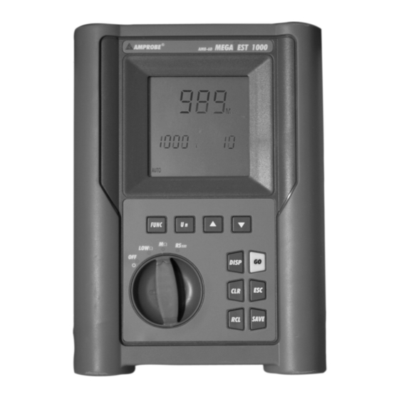
- Página 6 INSTRUMENT DESCRIPTION Rotary switch: Selects the instrument DISPLAY function CLEAR SAVE RECALL Front panel of the Instrument Rotary Switch Positions LOWΩ: Continuity test of earth, protective and equalising potential conductors with test current higher than 200 mA and open circuit voltage ranging from 4V to 24V. MΩ: Measurement of insulation resistance with DC test voltage 50V, 100V, 250V, 500V or 1000V.
- Página 7 Definition of Keys FUNC Multifunction key to select measuring mode. Key for selection the rated voltage during test of insulation resistance. Key used to increase the test duration interval or to scroll the results of the stored tests. Key used to decrease the test duration interval or to scroll the results of the stored tests.
- Página 8 CALIBRATION PROCEDURE 1. Select mode CAL by means of the FUNC key. 2. Connect the black and blue cables to the instrument input terminals P and N respectively: Connection of instrument terminals during calibration procedure. 3. Connect the alligator clips to the test leads. 4.
- Página 9 CANCELLATION OF CALIBRATION PARAMETERS Message >5Ω: To cancel calibration parameters Ω means that the (and symbol CAL) o> 5 instrument detected Ω necessary recalibrate a resistance higher than 5Ω therefore it instrument with a resistance will proceed with higher than 5Ω (for example with Reset procedure.
- Página 10 SWITCH POSITION FUNCTIONS: “LOWΩ” POSITION 5.1.1 CONTINUITY TEST: Continuity test of earth, protective and equalizing potential conductors with a test current higher than 200 mA and open circuit voltage ranging from 4v TO 24v WARNING: Before carrying out the continuity test make sure that there is no voltage at the ends of the conductor under test.
- Página 11 5.1.2 "AUTO", "R+", "R-", "R+TIMER", "R-TIMER" MODES: 1. Select the desired mode by means of the FUNC key. 2. Connect the black and blue cables to the instrument input terminals P and N respectively. Connection of the instrument terminals during LOWΩ test. 3.
- Página 12 5.1.2.1 "AUTO" MODE At the end of the test, if the average Ω CAL LOW Average resistance value Ravg results to be 1.07 resistance lower than 5Ω the instrument emits a value Ravg. Ω double sound signal indicating the positive outcome of the test and displays one screen similar to the screen alongside.
- Página 13 5.1.2.4 ANOMALOUS CASES: Anomalous cases which can occur during the following "AUTO", "R+", "R-", "R+TIMER", "R-TIMER" ATTENTION: In case a value of Ravg or R+ or R- Ω CAL LOW average value higher than or equal to 5Ω but o 5.75 of Ravg higher Ω...
- Página 14 In case the mode R+TIMER or R- Ω CAL LOW 9.99Ω is the TIMER was selected and a R+ or R- maximum o> 9.99 Ω value which higher than 9.99Ω was detected, the instrument emits an intermittent measured in sound signal during the test, a - - - LOWΩ, long sound signal at the end of the...
- Página 15 “MΩ” POSITION 5.2.1 INSULATION RESISTANCE: INSULATION RESISTANCE MEASUREMENT WITH TEST VOLTAGE OF 50V, 100V, 250V, 500V OR 1000V ATTENTION: Before making the insulation test make sure that the circuit under test is not energised and all the relative loads are disconnected.
- Página 16 3. Connect the test leads to the object which is to be tested after deactivating the circuit to be tested and all the relative loads (see previous picture). By means of U select the test voltage suitable for the type of test to be carried out.
- Página 17 5.2.2.1 "MAN" MODE Press the GO key. The instrument effects the test lasting: Maximum 10 seconds in case the key is pressed and released within 5 seconds. Until the key is released for all the other cases. Note: Press the GO key again if the test is to be stopped Insulation At the end of the test, in case the resistance...
- Página 18 5.2.2.2 "AUTO" MODE Press the GO key. The instrument effects the measurement ending when the measured value gets stable. Note: Press the GO key again if the test is to be stopped At the end of the test, in case the Insulation resistance value...
- Página 19 5.2.2.3 "TIMER" MODE Press the GO key. The instrument effects the measurement ending when the set time has elapsed. 999 seconds → Maximum value of the test duration. 10 seconds → Minimum value of the test duration. Note: Pressing the GO key again the test gets immediately interrupted.
- Página 20 5.2.2.4 ANOMALOUS CASES: Anomalous cases which may occur during the insulation tests "MAN", "AUTO", "TIMER" Maximum The symbol ">" means that the resistance value R is higher than R resistance value which In case a value of MΩ higher than measured was detected (depending on the >...
- Página 21 ATTENTION: If the terminal voltage is higher than the test was not 30V, the instrument will not take the carried out. test, displays the screen alongside for Check that the 5 seconds after which, it shows the circuit is not energised.
- Página 22 HOW TO SAVE, RECALL AND CLEAR TEST DATA 5.3.1 SAVE If the results relative to the tests effected are to be stored you can proceed as follows: Press the SAVE key once. SAVE If the memory of the instrument is not empty it displays the screen to the right.
- Página 23 5.3.2 RECALL If you want to recall the stored test results proceed as follows: Press the RCL key. If the memory of the instrument is not empty displays screen alongside. Number of the memory location in which the measurement results were stored. Value of the parameter P related to the saved measurement.
- Página 24 5.3.3 CLEAR If you want to cancel the stored tests results proceed as follows: Press the RCL key. The instrument displays a screen like the following: Number of the memory location in which the measurement results were stored. Value of the parameter P related to the saved measurement.
- Página 25 Example: 97 tests have been stored in the instrument. If you want to cancel the tests from 43rd to 97 , you proceed as follows: Press RCL. Select with keys the memory location 43. Press CLR. You can see CLR blinking on the primary display, 43 on the left secondary display and 97 on the righ secondary display.
- Página 26 6. PRACTICAL EXAMPLES OF ELECTRICAL TESTS LOW CONTINUITY MEASUREMENT CONTINUITY MEASUREMENT ON PROTECTIVE CONDUCTORS PURPOSE OF THE TEST Check the continuity of: protective conductors (PE), main equalising potential conductors (EQP), secondary equalising potential conductors (EQS) in TT and TN-S systems. neutral conductors having functions of protective conductors (PEN) in TN-C system.
- Página 27 Check the continuity among: a) earth poles of all the plugs and earth collector or node. b) earth terminals of class I instruments (Boiler etc.) and earth collector or node. c) main external masses (water, gas pipes etc.) and earth collector or node. d) auxiliary external masses to the earth terminal.
- Página 28 Insulation measurements in a facility. A procedure indicating how to take the insulation resistance measurement of a facility is reported in the following table:...
- Página 29 Procedure for insulation resistance measurement referring to the previous picture: Judgement Switch situation Point under test Measurement result installation Se R ≥ R ☺ Turn the switch A, Take the measurement OK (end of the test) LIMITE l D and E off on switch A Proceed Se R<...
- Página 30 ALLOWABLE VALUES The values of test voltage and minimum insulation resistance are reported in the following table (CEI64-8/6 Tab. 61A): Rated circuit voltage Test voltage Insulation resistance (M###) SELV and PELV* ###0.250 Up to 500 V included, except for the ###0.500 above circuits.
- Página 31 CHECKING THE CIRCUIT SEPARATION PURPOSE OF THE TEST The test, to be made in case the protection is realised through separation (64-8/6 612.4, SELV or PELV or electrical separation), shall check that the insulation resistance measured according to the indications below (depending on the separation type) complies with the limits reported in the table relative to the insulation measurements.
- Página 32 EXAMPLE OF CHECKING THE SEPARATION AMONG ELECTRICAL CIRCUITS Transformer TEST AMONG ACTIVE PARTS. Connect a test lead instrument one of the two Between the active conductors of the parts secondary circuit separated circuit other and among those test lead to one other circuits of the conductors primary...
- Página 33 ALLOWABLE VALUES The test result is positive when the insulation resistance indicates values higher or equal to those indicated in the table reported in the section relative to insulation tests. Notes: • SELV system: is a system of category zero or very low safety voltage featured by: Power supply: autonomous source (ex.
- Página 34 Test b): Connect the instrument test leads to the electrodes placed on the floor at a reciprocal distance of one meter Equalizing potential node Test b): Connect one test lead of the instrument to the equalizing potential node and the other to one of the electrodes placed on the floor at distance higher than...
- Página 35 7. CONNECTING INSTRUMENT TO PC The connection between PC and instrument is realised through the serial port and optical serial cable, provided with the software package "SUPERLINK". Before making the connection it is necessary to select the COM port used for the transmission.
- Página 36 8. PRINTING OF DATA ON SERIAL PRINTER (OPTIONAL) ( NOT AVAILABLE through Amprobe) The connection between printer and instrument is realised through the serial port and optical serial cable, provided with the printer (optional). Available To transfer the stored data from the instrument to the printer keep to the following procedure: 1.
- Página 37 9. MAINTENANCE 9.1 GENERAL 1. The tester you have purchased is a precision instrument. Strictly follow the instructions for use and storage reported in this manual to avoid any possible damage or danger during use. 2. Do not use this tester under unfavourable conditions of high temperature or humidity. 3.
- Página 38 10. TECHNICAL SPECIFICATIONS TECHNICAL FEATURES Accuracy is indicated as [% of reading + number of digits]. It refers to the following atmospheric conditions: a temperature of 23°C ± 5°C with a relative humidity < 75%. Continuity Measuring range Resolution Test mode Accuracy (Ω) (Ω)
- Página 39 General specifications Mechanical features Dimensions: 222(L) x 162(La) x 57(H)mm Weight (batteries included): approx. 1000g Power supply Battery type: 6 each 1.5V “AA” batteries Low battery indication: The symbol is displayed when the battery voltage is too low. Battery life: About 40 hours in stand-by or 500 LowΩ...
- Página 40 STANDARD EQUIPMENT The package contains: • The instrument • Carrying Case • Owner’s Manual • Test Leads Set (includes: two leads with alligator clips and one test probe) • Optical Download Cable • CD-ROM with “SUPERLINK” software for downloading/reading measurements REPLACEMENT PARTS Part Description Part #...
- Página 41 If the instrument fails to operate, check battery, test leads, etc and replace as necessary. If the instrument still malfunctions, please call the phone number listed below: ---------------------------- Service Division AMPROBE INSTRUMENT Miami, Florida 33150 Tel: 800-327-5060 Outside the U.S.A. the local Amprobe representative will Assist you.
- Página 42 Miami, FL 33150 (305) 423-7500 (800) 327-5060...
- Página 43 Copyright Amprobe 2003...
- Página 45 AMPROBE MULTITEST1000 Indice: PRECAUCIONES Y MEDIDAS DE SEGURIDAD ............3 1.1. INSTRUCCIONES PRELIMINARES .................3 1.2. DURANTE EL USO ......................4 1.3. DESPUES DEL USO......................4 DESCRIPCION GENERAL ..................5 2.1. FUNCIONES........................5 2.2. DESCRIPCION DEL INSTRUMENTO ................6 PREPARACION PARA EL USO ................7 3.1. CONTROLES INICIALES ....................7 3.2.
- Página 46 AMPROBE MULTITEST1000 11.2. MEDIDA DE LA RESISTENCIA DE AISLAMIENTO DE INSTALACIÓN ELECTRICA (250VDC, 500VDC, 1000VDC)..................46 11.3. MEDIDA DE LA RESISTENCIA DE AISLAMIENTO DE SUELOS EN LOCALES DE USO MEDICO........................48 11.4. VERIFICACION DE LA SEPARACIÓN DE LOS CIRCUITOS ........49 11.5. MEDIDA DE LA RESISTENCIA DE TIERRA, METODO VOLTIAMPERIMETRICO..52 11.6.
- Página 47 AMPROBE MULTITEST1000 1. PRECAUCIONES Y MEDIDAS DE SEGURIDAD El instrumento ha sido proyectado en conformidad a las directivas EN61557 y EN 61010-1 relativas a los instrumentos de medida electrónicos. ATENCIÓN Para su seguridad y para evitar dañar al instrumento, Le rogamos que siga los procedimientos descritos en el presente manual y lea con particular atención todas las notas precedidas por el símbolo...
- Página 48 AMPROBE MULTITEST1000 Le sugerimos que siga las reglas de seguridad orientadas a: Protegerle contra corrientes peligrosas. Proteja el instrumento contra un uso erróneo. Sólo los accesorios incluidos con el equipo garantizan las normas de seguridad. Deben estar en buenas condiciones y si fuese necesario, sustituirlos por los modelos originales.
- Página 49 AMPROBE MULTITEST1000 2. DESCRIPCIÓN GENERAL Le agradecemos que haya escogido un instrumento de nuestro programa de ventas. El instrumento que acaba de adquirir, si se utiliza según lo descrito en el presente manual, le garantizará medidas precisas y fiables. El instrumento está realizado de modo que garantiza la máxima seguridad gracias a un desarrollo de nueva concepción que asegura el doble aislamiento y el cumplimiento de la...
- Página 50 AMPROBE MULTITEST1000 2.2. DESCRIPCION DEL INSTRUMENTO LEYENDA: Visualizador Teclas Función Conmutador rotatorio ∆ n FUNC DIST START STOP DISP SAVE Tecla FUNCION para seleccionar la modalidad de medida. FUNC Tecla U / DIST para seleccionar la tensión nominal o distancia dependiendo de la medida seleccionada.
- Página 51 De todas formas se aconseja controlar exhaustivamente el instrumento para comprobar que no haya sufrido daños durante el transporte. Si se detecta alguna anomalía contacte inmediatamente con la sociedad Amprobe. Se aconseja además controlar que el embalaje contenga todas las partes indicadas en el párrafo 14.5.
- Página 52 AMPROBE MULTITEST1000 3.5. SELECCIÓN DE IDIOMA Y UNIDAD DE MEDIDA Es posible configurar el idioma y la unidad de medida (en resistividad de terreno) siguiendo el procedimiento: 1. Mientras mantiene la tecla FUNC pulsada, encienda el instrumento ON (la posición del conmutador no es relevante.
- Página 53 AMPROBE MULTITEST1000 4. DESCRIPCIÓN DEL CONMUTADOR DE FUNCIONES 4.1. LOWΩ: PRUEBA CONTINUIDAD CONDUCTORES PROTECCIÓN Y EQUIPOTENCIALIDAD Las pruebas se realizan a una corriente de prueba superior a 200 mA y una tensión de cortocircuito desde 4 a 24V DC de acuerdo a EN 61557-2 y VDE 0413 parte 4.
- Página 54 AMPROBE MULTITEST1000 4.1.1. Modalidad "CAL" 1. Seleccione la modalidad CAL usando la tecla FUNC. 2. Inserte el cable Negro y el cable Azul en los respectivos terminales de entrada T1 y T4 del instrumento Conexión de los terminales del instrumento durante el procedimiento de calibración 3.
- Página 55 AMPROBE MULTITEST1000 PUNTAS DE PRUEBA Asegurarse siempre, antes de cada medida, que la calibración se refiera a los cables utilizados en el momento. En una medida de continuidad si el valor de resistencia depurado de la calibración (es decir valor de la resistencia menos el valor del offset de la calibración) resultase negativo, se...
- Página 56 AMPROBE MULTITEST1000 4.1.2. Procedimiento de medida para la continuidad de los conductores equipotenciales modalidad AUTO, R+TIMER, R-TIMER 1. Seleccione con la tecla FUNC la modalidad que interese. 2. Inserte el cable Negro y el Azul en los correspondientes terminales de entrada T1 y T4 del instrumento Conexión de las terminales del instrumento prueba LOW Ω.
- Página 57 AMPROBE MULTITEST1000 4.1.2.1. Mode "AUTO" Valor medio de la Al término de la prueba, en el caso en que Ω CAL LOW resistencia Ravg el valor medio de la resistencia Ravg 1.07 Ω resulta inferior a 5 Ω, el instrumento emite una doble señal acústica que...
- Página 58 AMPROBE MULTITEST1000 4.1.3. Situaciones anómalas en las que se puede encontrar durante las pruebas AUTO, R+TIMER, R- TIMER Sólo si ha sido En el caso en que haya detectado una Ω seleccionada CAL LOW Ravg o R+ o R - superior o igual a 5 modalidad 5.75...
- Página 59 AMPROBE MULTITEST1000 4.2. MΩ: MEDIDA DE LA RESISTENCIA DE AISLAMIENTO CON TENSIÓN DE PRUEBA DE 50V, 100V, 250V, 500V O 1000V Referente a EN 61557-2 y VDE 0413 parte 1. ATENCIÓN Antes de realizar la prueba de aislamiento asegurarse que el circuito en examen no esté...
- Página 60 AMPROBE MULTITEST1000 4.2.1. Procedimiento de prueba de la resistencia de aislamiento en todas las modalidades 1. Seleccione con la tecla FUNC la modalidad que interese. 2. Inserte el cable Negro y el cable Azul en los correspondientes terminales de entrada T1 y T4 del instrumento, Aislamiento entre Fase y Tierra en una instalación eléctrica.
- Página 61 AMPROBE MULTITEST1000 ATENCIÓN Si en el visualizador del instrumento aparece el mensaje “Measuring” el instrumento está ejecutando la medida. No desconecte nunca las puntas de prueba durante la medida ya que el circuito en examen podría quedar cargado a una tensión peligrosa a causa de la capacidad parásita de la instalación.
- Página 62 AMPROBE MULTITEST1000 4.2.1.1. Modalidad "MAN" START Pulse la tecla START/STOP. STOP El instrumento efectúa la medida con una duración: Mínimo 4 segundos en el caso de pulsar y soltar la tecla. Siempre que la tecla no esté en todos los otros casos.
- Página 63 AMPROBE MULTITEST1000 4.2.1.2. Modalidad "TIMER" 6. Use las siguientes teclas para seleccionar la duración de la prueba: Pulse esta tecla para aumentar la duración de la prueba (Tmax=999 segundos). Pulse esta tecla para disminuir la duración de la prueba (Tmin=10 segundos).
- Página 64 AMPROBE MULTITEST1000 4.2.2. Situaciones anómalas en la que se puede encontrar durante las pruebas "MAN" & "TIMER" Al término de la prueba, en el caso en El símbolo ">" que el valor de la resistencia R >999 significa que el MΩ...
- Página 65 AMPROBE MULTITEST1000 4.3. INDICADOR DE SECUENCIA DE FASES Gire el conmutador en la posición. Encienda el instrumento. ATENCIÓN No desconectar nunca los terminales de los puntos de medida cuando el instrumento visualiza el mensaje "MEASURING" SP - 21...
- Página 66 AMPROBE MULTITEST1000 4.3.1. Modalidad " " 1. Conecte los tres cables negro, rejo y verde en las correspondientes terminales de entrada del instrumento T1, T2, T3. Inserte los extremos de los cables libres en los cocodrilos. Conexión del instrumento para la indicación del sentido cíclico de las fases L1= cable negro, L2= cable azul, L3= cable verde 2.
- Página 67 AMPROBE MULTITEST1000 4.3.2. Situaciones anómalas que se puede encontrar durante las pruebas de Sentido Cíclico de las Fases Mensaje “Lo En el caso en que el instrumento VOL tAG”: detecte al menos una de las tensiones el instrumento presentes entre dos de las fases en...
- Página 68 AMPROBE MULTITEST1000 Si un cable no está conectado a la Cable negro= L1 instalación o una fase no está presente, está el instrumento visualizará la siguiente conectado a una pantalla fase instalación. Cable negro= L1 no está conectado a una fase de Tensión entre la...
- Página 69 AMPROBE MULTITEST1000 EARTH ρ: MEDIDA DE LA RESISTENCIA DE TIERRA Y DE LA RESISTIVIDAD 4.4. DEL TERRENO Gire el conmutador en posición EARTH ρ. Encienda el instrumento. La tecla FUNC permite seleccionar una de las siguientes modalidades (que FUNC se presentan en orden cíclico): Modalidad “2P”...
- Página 70 AMPROBE MULTITEST1000 4.4.1. Procedimiento de medida para la modalidad de prueba "2P" 1. Seleccione "2P" modalidad de medida de tierra usando la tecla FUNC. 2. Conecte los cables Negro, Rojo, Verde y Azul a los respectivos terminales de entrada del instrumento T1, T2, T3, T4 (ver posibles conexiones siguientes).
- Página 71 AMPROBE MULTITEST1000 Cuando las condiciones de trabajo impiden la realización de la modalidad de “3P” como por ejemplo en el centro de la ciudad. En sistemas TT es posible medir la resistencia de tierra con el método simplificado “2P” que proporciona un valor superior a la modalidad “3P”.
- Página 72 AMPROBE MULTITEST1000 4.4.1.1. Medida de la resistencia de tierra desde una toma de corriente En instalaciones TT es posible realizar medidas de tierra con el método simplificado que proporciona un valor por exceso (por lo tanto más seguro), utilizando el NEUTRO de la compañía eléctrica tomado directamente de la toma de corriente como pica auxiliar;...
- Página 73 AMPROBE MULTITEST1000 4.4.2. Procedimiento de medida para la modalidad de prueba "3P" Las medidas son realizadas de acuerdo a las normas CEI 64.8, IEC 781, VDE 0413, EN61557-5. 1. Seleccione la modalidad de medida de tierra "3P" usando la tecla FUNC.
- Página 74 AMPROBE MULTITEST1000 Nota: Si la tecla START/STOP es pulsada y mantenida, el instrumento realizará más pruebas consecutivas. 5. Cuando un nuevo valor ha sido adquirido el instrumento emite un corto sonido y calcula el nuevo valor promedio. 6. Pulse la tecla DISP mostrará el valor promedio calculado y la modalidad DISP de promedio.
- Página 75 AMPROBE MULTITEST1000 4.4.3. Modalidad "ρ": procedimiento de medida La resistividad de terreno es una medición muy útil. Su valor puede ayudar a diseñar correctamente el sistema de Tierras. Las medidas son realizadas de acuerdo a las normas CEI 64.8, IEC 781, VDE 0413, EN61557-5 1.
- Página 76 AMPROBE MULTITEST1000 ρ Al finalizar la prueba el instrumento 36.5 visualizará la siguiente pantalla. Ω Valor de la Resistividad de tierra 0.93 Ω ATENCIÓN No desconectar nunca los terminales de los puntos de medida cuando el instrumento visualiza el mensaje "MEASURING"...
- Página 77 AMPROBE MULTITEST1000 SITUACIONES ANOMALAS MODALIDAD EARTH ρ 4.5. sistema amperimétrico está rC indica un valor cortado, cuando pulsamos alto resistencia. START/STOP el instrumento no puede medir la corriente mínima, por tanto - - - aparecerá pantalla como siguiente. Asegúrese terminales estén...
- Página 78 AMPROBE MULTITEST1000 Si la medida de la resistividad es mayor 12.55KΩm es el que el siguiente valor 1999x6.28x margen superior >12.55 Ωm (distancia entre picas seleccionada), instrumento distancia= después de pulsar START/STOP el Ω 3- - - instrumento realiza la prueba y aparece la siguiente pantalla.
- Página 79 AMPROBE MULTITEST1000 5. COMO GUARDAR, RECUPERAR Y BORRAR DATOS GUARDADOS EN MEMORIA 5.1. TECLA GUARDAR: "SAVE" Si los resultados relativos a las pruebas realizadas van a ser guardados debe proceder como se indica a continuación: SAVE Pulse la tecla SAVE una vez.
- Página 80 AMPROBE MULTITEST1000 5.2. TECLA RECUPERAR: "RCL" Si se quieren consultar los resultados relativos a las pruebas efectuadas y memorizadas proceda del siguiente modo 1. Pulse la tecla RCL/ESC Si la memoria del instrumento no está vacía visualizará siguiente pantalla. Número de la posición de memoria en el que será...
- Página 81 AMPROBE MULTITEST1000 5.3. BORRAR: TECLA “CLR”. Si se quieren borrar los resultados relativos de algunas pruebas efectuadas y memorizadas proceda del siguiente modo: 1. Pulse la tecla RCL/ESC. El instrumento visualizará la siguiente pantalla: Número de la posición de memoria en el que será...
- Página 82 AMPROBE MULTITEST1000 6. RESETEADO INSTRUMENTO PARÁMETROS ESTÁNDAR ANTES DE EFECTUAR UN RESETEADO DEL INSTRUMENTO GUARDE TODOS LOS DATOS RELATIVOS A LAS MEDIDAS EFECTUADAS DESCARGÁNDOLOS EN EL 6.1. PROCEDIMIENTO DE RESETEADO 1. Pulse las teclas DISP, CLR, RCL y la tecla ON/OFF.
- Página 83 AMPROBE MULTITEST1000 7. CONEXIÓN DEL INSTRUMENTO A UN PC La conexión entre un PC y el instrumento se realiza mediante una conexión al puerto serie mediante el paquete de software. Antes de efectuar la conexión es necesario que seleccione el puerto COM utilizado para la transmisión.
- Página 84 AMPROBE MULTITEST1000 8. MANTENIMIENTO 8.1. GENERALIDADES 1. El instrumento que Usted ha adquirido es un instrumento de precisión. Durante el uso y el almacenamiento respete las recomendaciones enumeradas en este manual para evitar posibles daños o peligros durante el uso.
- Página 85 AMPROBE MULTITEST1000 9. ESPECÍFICACIONES TÉCNICAS 9.1. CARACTERÍSTICAS TÉCNICAS La precisión está indicada como [% de la lectura ± número de cifras]. Está referida a las siguientes condiciones atmosféricas listadas en el párrafo 9.2.1. - Continuidad (LOWΩ) Modalidad de prueba Precisión Rango de Medida (Ω)
- Página 86 AMPROBE MULTITEST1000 - Medida de resistividad ρ Rango de Medida (Ω) Resolución (Ωm) Precisión 0.06 ÷ 19,99 Ωm 0,01 Ωm 20.0 ÷ 199.9 Ωm 0.1 Ωm 200 ÷ 1999 Ωm 1 Ωm ±(5% lec + 3 dgt) 2,00 ÷ 19,99 kΩm 0.01 kΩm...
- Página 87 AMPROBE MULTITEST1000 9.2. AMBIENTE 9.2.1. Condiciones ambientales de uso Temperatura de referencia: 23° ± 5°C 0°C ÷ 40 °C Temperatura de uso: Humedad relativa admitida: <80% -10 ÷ 60 °C Temperatura de almacenamiento: Humedad de almacenamiento: <80% 9.2.2. EMC Este instrumento está proyectado conforme las normas EMC en vigor y la compatibilidad han sido comprobadas relativamente para EN61326-1 (1998) + A1 (1999).
- Página 88 Departamento de Reparaciones ATP – Amprobe, TIF, Promax Miramar, FL Phone: 954-499-5400...
- Página 89 AMPROBE MULTITEST1000 FICHAS PRÁCTICAS PARA LAS VERIFICACIONES ELÉCTRICAS 11.1. LOWΩ: MEDIDA DE LA CONTINUIDAD DE LOS CONDUCTORES DE PROTECCIÓN OBJETIVO DE LA PRUEBA Verificar la continuidad de: conductores de protección (PE), conductores equipotenciales principales (EQP), conductores equipotenciales secundarios (EQS) en los sistemas TT y TN-S.
- Página 90 AMPROBE MULTITEST1000 Verifique la continuidad entre: a) Polos de tierra de todas las tomas de corriente y colector o nodo de tierra. b) Bornes de tierra de los aparatos de clase I (calentadores, etc.) y colectores o nodo de tierra.
- Página 91 AMPROBE MULTITEST1000 Resistencia de Tensión de Tensión nominal del circuito (V) Aislamiento prueba (V) (MΩ) ≥0.250 SELV Y PELV * Hasta 500 V comprendidos, excluidos los ≥0.500 circuitos sobre ≥1.000 Más de 500 V 1000 * Los términos SELV y PELV reemplazan en la nueva redacción de la normativa las antiguas definiciones "Baja tensión de seguridad o funcional."...
- Página 92 AMPROBE MULTITEST1000 11.3. MEDIDA DE LA RESISTENCIA DE AISLAMIENTO DE LOS SUELOS EN LOCALES DE USO MÉDICO OBJETIVO DE LA PRUEBA Verificar que el suelo sea realizado con materiales cuya resistencia de aislamiento esté conforme a lo previsto de las normas CEI 64-4 (3.05.03).
- Página 93 AMPROBE MULTITEST1000 11.4. VERIFICACIÓN DE LA SEPARACIÓN DE LOS CIRCUITOS Objetivo de la prueba La prueba, a efectuar en el caso en que la protección se active a través de separación ( 64-8/6 612.4, SELV o PELV o Separación Eléctrica), tiene que verificar que la resistencia de aislamiento medida sea descrita como a continuación (según el tipo de separación) es...
- Página 94 AMPROBE MULTITEST1000 Separación de protección respecto a otros sistemas eléctricos (doble aislamiento o reforzado o bien un apantallamiento metálico unido a tierra). Presenta puntos derivados a tierra (aislado por tierra). • Separación Eléctrica: es un sistema caracterizado por: Alimentación: transformador separador o fuente autónoma con características equivalentes (ej.
- Página 95 AMPROBE MULTITEST1000 EJEMPLO DE VERIFICACIÓN DE SEPARACIONES ENTRE CIRCUITOS ELÉCTRICOS Transformador de aislamiento o de seguridad que efectúa la separación entre los circuitos. Between the active parts of the separated circuit... Prueba entre las partes activas. conecte ...And among those...
- Página 96 AMPROBE MULTITEST1000 11.5. MEDIDA DE LA RESISTENCIA DE TIERRA, MÉTODO VOLTIAMPERIMÉTRICO Técnica para dispersores de tierra de pequeñas dimensiones Se hace circular una corriente entre el dispersor de tierra en examen y una sonda de corriente posicionada a una distancia del contorno de la instalación de tierra igual a 5 veces la diagonal del área que delimita la instalación de tierra.
- Página 97 AMPROBE MULTITEST1000 11.6. MEDIDA DE LA RESISTIVIDAD DEL TERRENO OBJETIVO DE LA PRUEBA Analizar el valor de la resistividad del terreno para definir, en fase de proyecto, la tipología de los dispersores de tierra a utilizar en la instalación. EQUIPAMIENTO PARA LA PRUEBA Para la medida de resistividad no existe valores admisibles, los varios valores obtenidos utilizando distancias entre las picas “a”...
- Página 98 AMPROBE MULTITEST1000 ρ Curva sólo disminuye en profundidad es posible sólo utilizar un dispersor en profundidad. Curva 2: ya que ρ diminuye sólo hasta profundidad aumento de la profundidad de otros dispersores comporta ninguna ventaja. Curva 3: con el aumento de la...
- Página 100 Miramar, FL Phone: 954-499-5400 Fax: 954-499-5454 www.amprobe.com...