Tabla de contenido
Publicidad
Enlaces rápidos
Publicidad
Tabla de contenido

Manuales relacionados para Hyundai N700E


Resumen de contenidos para Hyundai N700E
- Página 1 N700E MANUAL INSTRUCCIONES N700E MANUAL INSTRUCCIONES...
- Página 2 N700E-055LF/075LFP ~ N700E-370HF/450HFP Todos 10KA N700E-450HF/550HFP ~ N700E-3500HF/3800HFP Todos PROTECCIÓN SOBRE VELOCIDAD] Este inversor proporciona protección sobre velocidad PROTECCIÓN SOBRE CARGA] Este inversor proporciona protección...
-
Página 3: Seguridad
MANUAL INSTRUCCIONES SEGURIDAD Para jores resultados variador serie N700E, este manual atención todas señales advertencia colocadas aparato. Antes instalar operar equipo, siga instrucciones. Guarde este manual para cualquier consulta rápida. SÍMBOLOS DEFINICIONES instruccion seguridad ( ensaje ) es símbolo peligro... - Página 4 N700E MANUAL INSTRUCCIONES PRECAUCIÓN Este uipo deber a í estar instalado, ustado mantenido personal mantenimiento é ctrico cualificado familiar construcción operación uipamiento peligros implicados. incumplimiento esta precaución podr a í resultados lesiones corporales. usuario responsable asegurar toda uinaria accionada, unidad...
-
Página 5: Contaminación
MANUAL INSTRUCCIONES NOTA : GRADO CONTAMINACIÓN inversor debe utilizar medio ambiente grados contaminación construcciones típicas reducen posibilidad contaminación conductora recinto ventilación filtrado recinto ventilado cuando ventilación forzada, decir, ventilación logra mediante más fuelles dentro recinto proporcionan entrada positiva escape. - Página 6 Temparatura ambiente : -10 - +40℃ b. Humedad : 20 a 90% RH(sin condensación c. Vibración : 5.9 M/S (0.62G) 10 – 55HZ (N700E-5.5 ~ 22KW) d. Ubicación : 1000 metros menos altitud interiores (Sin corrosivo...
-
Página 7: Conformidad Ala Directiva
N700E MANUAL INSTRUCCIONES CONFORMIDAD DIRECTIVA BAJA TENSIÓN (LVD) caja protección debe cumplir Reglamento baja tensión. variador puede montando armario añadiendo cubiertas siguiente: ENVOLVENTE CUBIERTA variador debe instalado armario tiene grado protección tipo IP2X. Además superficies superiores armario fácil acceso reunirá... -
Página 8: Manual De Advertenciasy
TAMAÑO MODELO VARIADOR APRIETE DIÁMETRO TERMINAL [LB -IN] (AWG) Ancho áx. [mm] N700E- Carga pesada Carga Normal) N700E-055LF/075LFP 12.4 10.6 N700E-075LF/110LFP 12.4 10.6 N700E-110LF/150LFP 26.6 N700E-150LF/185LFP 26.6 N700E-185LF/220LFP 35.4 N700E-220LF 35.4 N700E-055HF/075HFP 12.4... - Página 9 N700E MANUAL INSTRUCCIONES TAMAÑO FUSIBLE ñ a especificado este manual para indicar unidad debe conect normativa para protección, 600V corriente nomina lista fusibles como muestra siguiente tabla: FUSIBLE [A] MODELO VARIADOR N700E-055LF/075LFP N700E-075LF/110LFP N700E-110LF/150LFP N700E-150LF/185LFP N700E-185LF/220LFP N700E-220LF N700E-055HF/075HFP N700E-075HF/110HFP N700E-110HF/150HFP...
-
Página 10: Definiciones Símbolos
N 00E MANUAL INSTRUCCIONES mación gene segu DEFINICIONES SÍMBOLOS instrucción seguridad (mensaje) incluye símbolo alerta señal mensaje, peligro precaución. Cada señal mensaje tiene significado siguiente Este símbolo "triángulo advertencia". Ocurre cualquiera palabras aviso: PELIGRO CUIDADO, como describe continuación: : Indica situación potencialmente peligrosa... -
Página 11: Instalación
N700E MANUAL INSTRUCCIONES mación gene segu 1. Instalación Asegúrese instalar unidad sobre superficie resistente fuego, como metal. caso contrario, existe peligro incendio. colocar nada altamente inflamable proximidades. caso Asegúrese contrario, existe peligro incendio. transporte unidad cubierta superior,... - Página 12 STRUCC mación gene segu 2. Cableado caso contrario, existe peligro Aseg ú rese conectar unidad toma tierra choque eléctrico fuego. trabajo cableado debe realizado electricista cualificado. caso contrario, existe peligro choque eléctrico fuego. cableado después verificar fuente alimentación está...
-
Página 13: Operación
N700E MANUAL INSTRUCCIONES mación gene segu Control Operación Mientras variador está conectado tensión segurese tocar terminales principales. caso contrario existe riesgo descarga eléctrica. Asegúrese encender fuente alimentación siempre cuando caja frontal está cerrada. Mientras variador está conectado temsión asegúrese... -
Página 14: Mantenimiento/Inspección
N700E MANUAL INSTRUCCIONES mación gene segu caso aletas ontrario, efrigeración xiste peligro endrán quemarse emperatura alta. Asegúrese tocarlos. Baja alta operación velocidad puede ajustar facilmente. Asegúrese operarlo espués comprobar tolerancia motor máquina. caso contrario, existe peligro daños y/o lesiones. - Página 15 Questions and Warranty of the Unit ................1-2 Questions on Unit ......................1-2 1.2.1 Warranty for the unit ..................... 1-2 1.2.2 Appearance ........................1-3 N700E-055LF/075LFP ~ N700E-220HF/300HFP ............1-3 1.3.1 N700E-300HF/370HFP ~ N700E-1320HF/1600HFP ............. 1-4 1.3.2 N700E-1600HF/2000HFP ~ N700E-2200HF/2500HFP ..........1-5 1.3.3 N700E-2800HF/3200HFP ~ N700E-3500HF/3800HFP ..........
-
Página 16: Tabla De Contenido
N700E MANUAL INSTRUCCIONES ......4-1 Function List ......................... 4-4 Monitor Mode (d-group) ....................4-4 4.2.1 Trip & Warning monitor mode (d-group) ..............4-5 4.2.2 Basic Function Mode ....................4-6 4.2.3 Expanded Function Mode of A Group ................4-7 4.2.4 Expanded function mode of b group ................4-14 4.2.5... -
Página 17: Descripción General
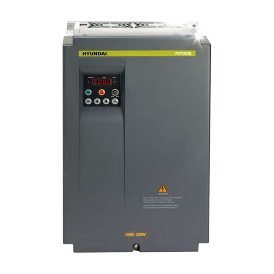
Asegúrese producto usted ordenó marcando especificación etiqueta Fig1-1 Frontal variador N700E Model : N700E-110LF/150LFP Max Temp : 40deg OUTPUT CAPACITY : 17.1kVA / 19kVA IP20 INPUT : 3Ph, 200-240V, 50/60Hz, 47.4A OUTPUT : 3Ph, 0-240V, 0.1-400Hz, 45A(HD) BAR CODE... -
Página 18: Preguntas Y Garantía De La Unidad
1.2.1 • Si tiene alguna pregunta relacionada daños unidad, elementos desconocidos para consultas generales, favor póngase contacto distribuidor HYUNDAI LOCAL siguiente información: (1) Modelo variador Número serie (Serial No.) Fecha compra Motivo llamada ① Parte dañada condición ② Partes desconocidas contenidos Garantía... -
Página 19: Apariencia
700E ANUAL RUCCI Apariencia N700E-055LF/075LFP ~ N700E-220HF/300HFP 1.3.1 Teclado Cubierta delantera Fig1-3 Vista parte delantera Terminales circuito control Terminales circuito principal Fig1-4 Vista cubierta frontal... - Página 20 N700 MANUAL INSTRUCCION 1.3.2 N700E-300HF/370HFP ~ N700E-1320HF/1600HFP Teclado Cubierta delantera Fig1-5 ista parte delantera Terminales circuito control Terminales circuito principal Fig1-6 Vista cubierta frontal...
- Página 21 N700E MANUAL INSTRUCCIONES 1.3.3 N700E-1600HF/2000HFP ~ N700E-2200HF/2500HFP Teclado Cubierta delantera Fig1-7 Vista parte delantera Terminales circuito control Terminales circuito principal Fig1-8 Vista cubierta frontal...
- Página 22 N700 MANUAL INSTRUCCION N700E-2800HF/3200HFP ~ N700E-3500HF/3800HFP 1.3.4 Teclado Cubierta delantera Fig1-9 Vista parte delantera Terminales circuito control Terminales circuito principal Fig1-10 ista cubie ontal...
-
Página 23: Instalación Y Cableado
N700 MANUAL INSTRUCCION 2.2. Instalación cableado 2.1 Instalación Aseg ú rese instalar unidad sobre superficie resistente fuego, como etal. caso contrario, existe peligro incendio Aseg ú rese colocar nada inflamable proximidades. caso contrario, existe peligro incendio. transporte unidad cubierta superior, lleve... - Página 24 N700E MANUAL INSTRUCCIONES 2.1.1 Instalación (1) Transporte: Este varaidor tiene partes plactico Manejalo cuidado apriete demasiado fijacione soportes pueden romperse causando riesgo caída. instale utilice variador parece estar dañado faltan piezas (2) Superficie para montaje inversor: temperatura disipador calor variador...
- Página 25 N700E MANUAL INSTRUCCIONES (6) Posición montaje: variador debe montado posición vertical mediante tornillos pernos. superficie montaje también debe estar libre vibraciones puede mantener fácilmente peso variador Fig 2-2 Posición montaje (7) Ventilación dentro recinto: instalar varios variadores recinto, debe instalar también...
- Página 26 ases 200 to 240V 50/60Hz (Mod o el : N700E-055LF/075LFP ~ 220LF) ases 380 to 480V 50/60Hz (Mod o el : N700E-055HF/075HFP ~ 3500HF/3800HFP) Asegúrese conectar tres fases entrada. caso...
-
Página 27: Conexión De Los Terminales
N700E MANUAL INSTRUCCIONES 2.2.1 Diagrama conexión terminales N700E Power Supply 3 Phase 200V : 200 ~ 240V 400V : 380 ~ 480V Rectifier Inverter (50/60Hz ±10%) Power Circuit Signals Control Circuit Short Bar Control RB : 5.5KW(HD) ~ 22KW(HD) N : 30KW(HD) ~ 350KW(HD) - Página 28 N700E MANUAL INSTRUCCIONES (1) Explicación terminales circuito principal Descripción Señal Nombre terminal R, S, T (L1,L2,L3) Conexión alimentación entrada Alimentación principal U, V, W (T1,T2,T3) Salida variador Conexión 3-fases motor Despues quitar barra entre conectar reactancia para Reactancia C.C PD,P (+1,+)
-
Página 29: Circuito Principal
N700E MANUAL INSTRUCCIONES 2.2.2 Cableado circuito principal (1) Advertencia sobre cableado Para llevar cabo trabajo cableado variador, espere menos diez minutos antes retirar cubierta. Asegúrese verificar indicador carga ilumina. comprobación final debe hacerse siempre medidor voltaje. Después retirar fuente alimentación,... - Página 30 N700E MANUAL INSTRUCCIONES ⑤ Terminales conexión unidad frenado regenerativo (P,N) variadores potencia más llevan circuito BRD. requiere el frenado regenerativo circuito externo (opción) requiere además resistencia (opcional). Conecte terminales unidad frenado regenerativo externos terminales variador unidad frenado...
- Página 31 Tornillo Ancho Tipo variador N700E-055LF/075LFP ( ) RB ( 1) N700E -075LF/110LFP (L1) (L2) (L3) (T1) (T2) (T3) N700E -055HF/075HFP 10.6 N700E - 075HF/110HFP N700E-110HF/150HFP (L1) (L2) (L3) (+1) (T1) (T3) N700E-110LF/150LFP N700E-150LF/185LFP ( ) RB ( 1) N700E-150HF/185HFP (L1) (L2)
- Página 32 N700E MANUAL INSTRUCCIONES (+1) N700E-1600HF/2000HFP N700E-2200HF/2500HFP (L1) (L2) (L3) (T1) (T2) (T3) N700E-2800HF/3200HFP (+1) N700E-3500HF/3800HFP (L1) (L2) (L3) (T1) (T2) (T3) Table 2-3 Bloque terminales circuito principal 2-10...
- Página 33 N700E MANUAL INSTRUCCIONES Nota equipo aplicable motor jaula ardilla cuatro polos estándar HYUNDAI (3) ccesorios Not 2 : Aseg ú rese usar capacidad adecuada interruptor autom á tico. Not 3: Aseg ú rese utili cable s á grande í l...
- Página 34 Modelo Variador motor Clase entre U,V,W, Contactor (N•m) Int. autom tico á terminal (kW) P,PD,N magn tico é (MCCB) (MC) N700E-055LF/075LFP HBS60N HiMC32 Más de 6 Más N700E-075LF/110LFP HBS60N HiMC32 Más N700E-110LF/150LFP HBS100N HiMC50 Clase 200V N700E-150LF/185LFP HBS100N 100A HiMC6 5 Más...
- Página 35 Termi a n l variador U,V,W, automático (N•m) mágnetico (kW) variador P,PD,N (MCCB) (MC) otor HBS60N HiMC32 s á s á N700E-055LF/075LFP HBS60N HiMC32 N700E-075LF/110LFP HBS100N HiMC50 s á Clase 200V N700E-110LF/150LFP HBS100N 100A HiMC65 s á de 25 18.5...
-
Página 36: Esquema De Conexión
DOP RXP RXN CM1 CM1 6 5 4 3 2 1 CM1 P24 H O OI L L FM CM1 RN0 RN1 AL0 AL1 AL2 a.N700E #1 (5.5kW(HD) ~ 22kW(HD)) b.N700E #2 ~ #4 (30kW(HD) ~ 350kW(HD)) Fig 2-5 Esquema conexiones (2) Cableado ①... - Página 37 N700E MANUAL INSTRUCCIONES (3) Conexión salida controlador lógico programable (secuenciador) -J1(J3) : Interruptor selección modo funcionamiento (modo fuente). selección fuente energía señal (interno externa (J4) : - La conexión controlador lógico programable entrada (secuenciador) Modo fuente (Fuente alimentación interna) Modo...
- Página 38 N700E MANUAL INSTRUCCIONES (4) Conexión entrada controlador lógico programable (secuenciador). INVERTER INVERTER Fig 2-7 erminal salida conexión PLC. 2-16...
-
Página 39: Funcionamiento
N700E MANUAL INSTRUCCIONES 3. Funcionamiento Asegúrese tocar terminal principal para comprobar complemento señal eliminar cables connectores. ontrario existe peligro descarga eléctrica. Asegúrese apagar fuente alimentación entrada hasta después caja frontal esté cerrada. Mientras inversor esté cargado enérgicamente asegúrese... - Página 40 N700 MANUAL TRUCCION aletas refrigeración tendrán alta temperatura. Asegúrese tocarlos. existe peligro quemaduras. caso contrario, Bajo alta velocidad operación velocidad ariador puede configurar fácilmente. Asegúrese operarlo después comprobar tolerancia motor máquina. caso contrario, existe peligro ñ lesiones. nsta sistema renado terna...
-
Página 41: Operaciones
N700 MANUAL TRUCCION 3.1 Operaciones Este inversor requiere señales diferentes inversor funcione correctamente. inversor requiere tanto entorno operación señal ajuste frecuencia. continuación indican detalles cada método operación instrucciones necesarias para funcionamiento. CABLEADO EXTERNO 3.1.1 Ajuste Operación ajuste frecuencia control terminal (1) Este método controla... - Página 42 N 00E MANUAL INSTRUCCIONES Test de funcionamiento Este ejemplo conexión común. onsulte punto para utilización detallada operador digital. 3.2.1 juste operación frecuencia control terminal. Fig 3-1 rama configuración contro termina (Procedimiento) (1) Asegurese conexi ó estan protegidos correctamente. (2) Gire MCCB suministrar energ...
-
Página 43: Configuración
N 00E MANUAL INSTRUCCIONES juste configuración frecuencia desde operador digital 3.2.2 Fig 3-2 Setting diagram from the digital operator (Procedimiento) Asegurese conexiónes estan protegidos correctamente. Gire MCCB suministrar energía inversor. alimentación variador debe encenderse) Ajuste terminal selección ajuste frecuencia. Establecer código presionando tecla... - Página 44 N 00E MANUAL INSTRUCCIONES Listado codigos parametros Ope dor gital 4.1.1 Nombre contenido cada parte operador digital tipo estándar (1) P art general Botón STOP/RESET Esta tecla li í para parar motor resetear errores.(Cuando selecciona cualquier operador terminal, MARCHA esta tecla funciona.
- Página 45 N700E MANUAL INSTRUCCIONES ② Descripción tecla FUNC in RPM...
- Página 46 N700E MANUAL INSTRUCCIONES ③ Modo función extendida mapa navegación ④ Descripción : Cuando inversor activa, grupos visualización puede aparecer acuerdo valor ajuste (ajuste código pantalla)
-
Página 47: Funciones
N700E MANUAL INSTRUCCIONES Listado funciones 4.2.1 Modo pantalla (grupo-d) Codigo Descripción Nombre función Visualización tiempo real frecuencia salida motor desde 0.00 Frecuencia salida hasta 400.0 (Hz) Visualización tiempo real corriente salida motor desde 0.00 Corriente salida hasta 999.9 Hz (A) Tensión... -
Página 48: Historial De Disparos Y Modo De Adverencia (Grupo-D)
N700E MANUAL INSTRUCCIONES Historial disparos modo adverencia (grupo-d) 4.2.2 Codigo Descripció n Nombre funció n Mostrar evento disparo corriente: · Método visualización Motivo alarma ↓ Presione tecla rriba Frecuencia salida caso alarma ↓ Presione tecla Arriba/Abajo Corriente salida caso alarma... -
Página 49: Funcionamiento Básico
N700E MANUAL INSTRUCCIONES 4.2.3 Modo funcionamiento básico Editar el Valor Nombre función tiempo Codigo Descripció n defecto inicio recuencia stándar defecto determina constante motor determina velocidad motor constante, rango ajuste 0,00 400.0Hz. caso control vectorial sensor, rango ajuste 0,00 300.0Hz.) -
Página 50: Función Expandida
N700E MANUAL INSTRUCCIONES 4.2.4 Función expandida Modo Editar Valor Nombre función tiempo Descripción Codigo defecto inicio Ajuste parametros básicos Cuatro opciones : 0..Potenciometro Método ajuste 1..Control terminal entrada digital frecuencia (Ajuste multi-velocidad) 2..Operador estandar 3..O perator remoto (comunicación) - Página 51 N700E MANUAL INSTRUCCIONES Valor Editar Codigo Nombre función Descripción tiempo defecto inicio Dos opciones : : 0 I nicio desde frecuencia incio : 1 Inicio desde 0Hz Frquency (A06) Ajuste inicio (A09=0) frecuencia externa (A05) (A09=1) (A07) (A08) Analog input...
-
Página 52: Descripción
N700E MANUAL INSTRUCCIONES Editar Valor Nombre función Descripción Codigo tiempo defecto inicio Establece frecuencia Ajuste recuencia 100.0% refuerzo manual Dos curvas V/F : Tres opciones: 0... Par lineal 1... P ar reducido (Fuerza educida veces 2... C ontrol vectorial captador 100.0%... -
Página 53: Ajustes Frecuencia
N700E MANUAL INSTRUCCIONES Editar Valor Có d igo Nombre funció n Descripció n tiempo defecto inicio Ajustes frecuencia relacionada Establece lí m ite frecuencia, menor frecuencia má x ima (A04). rango 0,00 400.0Hz unidades 0,01 Upper limit (A38) A38 Límite superior 0.00Hz... -
Página 54: Regulación Automática De Tensión
N700E MANUAL INSTRUCCIONES Editar Valor Descripción Código Nombre función tiempo defecto inicio Función (AVR) Regulación automática tensión Automático (salida) regulación voltaje, selecciona desde tres tipos funciones 0... Siempre ON 1... Siempre OFF Selección AVR solo cuando 2... OFF desacelera función... - Página 55 N700E MANUAL INSTRUCCIONES Editar Valor Descripción Nombre función Código tiempo defecto inicio Ajuste curva característica Acc1 Acc2 0: Lineal 1: Curva S (tiempo max. acceleración: 39.0seg) 2: Curva U (tiempo max. acceleración 29.0seg) Selección curva S-curve aceleración Linear U-curve Target...
- Página 56 N700E MANUAL INSTRUCCIONES Nota1: A justes para diferentes tipos variador –Codigo A29(Par manual ganancia impulso 055LF~110LF, 055HF~110HF, 075LFP~110LFP, 075HFP~110HFP : 3.3% 150LF~220LF, 150HF~220HF, 150LFP~220LFP, 150HFP~220HFP : 3.1% 300HF~550HF, 300HFP~550HFP : 2.5% 750HF~1320HF, 750HFP~1320HFP : 2.1% 1600HFP : 1% 1600HF~3800HFP : 2.0% Nota2 : Realimentación...
-
Página 57: Función Reinicio
N700E MANUAL INSTRUCCIONES 4.2.5 Función expandida Modo Editar Valor Nombre función Descripción Código tiempo defecto inicio Función reinicio Select inverter restart method, four option codes: arma s é nici : 2 I nici ncia edef cuan inicia raci ó ncia... -
Página 58: Funciones Limitación
N700E MANUAL INSTRUCCIONES Editar Valor Nombre función Descripción tiempo Código defecto inicio Funciones limitación sobrecarga : 0 Modo restricci ó sobrecarga sobretensi ó Modo limitación Modo limitación sobrecarga sobrecarga sobretensión Modo limitación sobretensión Modo limitación sobrecarga sobretensión HD : 180%... -
Página 59: Otras Funciones
N 00E MANUAL INSTRUCCIONES Editar Valor Código Nombre Descripción tiempo defecto inicio Otras Funciones Establece frecuencia inicio salida variador Ajuste frecuencia 0.50Hz 0.50 a 10.00Hz unidades rango de : inicio Establece frecuencia portadora PWM, rango 1kHz a frecuencia máxima unidades 0.1kHz. -
Página 60: Other Function
Nota3 : Ajuste recuencia portadora tipos carga modelo variador Carga pesada (b26 = 0) Carga normal (b26 = 1) Modelo N700E-055LF/075LFP~185LF/220LFP 5.0kHz 2.0kHz N700E-055HF/075HFP~185HF/220HFP ¡ N700E-220LF 3.0kHz 2.0kHz N700E-220HF/300HFP~1320HF/1600HFP N700E-1600HF/2000HFP~3500HF/3800HFP 2.0kHz 2.0kHz ※ Por defecto b26=1,Todos modelos tienen misma frecuencia portadora 2.0kHz. -
Página 61: Expanded Function Mode Of C Group
N700E MANUAL INSTRUCCIONES 4.2.6 Expanded Function Mode of C Group Editar Valor Nombre Descripción Código tiempo defecto inicio Ajuste terminal entrada (dirección adelante) 1: RV (dirección inversa) (multi-velocidad (multi-velocidad (multi-velocidad3) (multi-velocidad4) 6: JG (jogging velocidad fija) (2-nivel comando accel decel... -
Página 62: Ajuste Estatus Terminal De Entrada
N700E MANUAL INSTRUCCIONES Editar Valor Nombre Descripción Código tiempo defecto inicio Ajuste estatus terminal entrada Select logic convention, two option codes: Ajuste contacto a/b de terminal 0: Normalmente abierto [NO] entrada (NO/NC) Normalmente cerrado [NC] Select logic convention, two option codes:... - Página 63 N700E MANUAL INSTRUCCIONES Editar Valor Código Nombre Descripción tiempo defecto inicio Output Terminal state setting Range is 0 to 250, resolution is 1 Ajuste ganancia analógica medida 100.0% Ajuste compensación analógica Range is -3.0 to 10.0% resolution is 0.1 0.0%...
-
Página 64: Expanded Function Mode Of H Group
0.001 - 30.00Ω ª 1 esistencia para motor Inductancia sobrecarga Lsig para 0.01 – 100.00mH motor 0.001 - 30.00Ω H10 Resistencia motor 0.01 – 100.00mH H11 Inductancia transitoria Note. N700E-1 0HF/2000HFP ~N7000E-3500HF/3800HFP do not support Expanded Function mode of H Group. 4-22... -
Página 65: Using Intelligent Terminals
N700E MANUAL INSTRUCCIONES 5. Using intelligent terminals Intelligent terminal lists Nombre Simbolo Descripción terminal terminal Forward SWF switch RUN/STOP Forward ON(closed) :Forward run terminal OFF(open) : stop Reverse SWR switch Reverse ON(closed) :Reverse run RUN/STOP OFF(open) :stop terminal 0-speed 3-speed... - Página 66 N700E MANUAL INSTRUCCIONES Nombre Simbolo Descripción terminal terminal Frequency When assign 13[AT signal] to code C01~C06 • command AT signal OFF : power terminal It is possible to command frequency using voltage signal terminal O-L(0~10V) • AT signal ON :...
-
Página 67: Monitor Terminal Function
N 00E MANUAL INSTRUCCIONES Monitor terminal function Monitor terminal function [FM] (analog) • The inverter provides an analog output terminal primary for frequency monitoring on terminal [FW] (output frequency, Output current, and output voltage monitor signal). • Parameter C17 selects the output signal data. When using the analog motor for monitoring, use scale reactor C18 and C19 to adjust the [FM] output so that the maximum frequency in the inverter corresponds to full-scale reading on the motor. -
Página 68: Intelligent Input Terminal Function
N 00E MANUAL INSTRUCCIONES Intelligent Input Terminal Function Forward Run/Stop [FW] and Reverse Run/Stop Command [RV] • When you input the Run command via the terminal [FW], the inverter executes the Forward Run command (high) or Stop command(low) • When you input the Run command via the terminal [RV], the inverter executes the Reverse Run command (high) or Stop command(low). - Página 69 N 00E MANUAL INSTRUCCIONES Multi-Speed Select [CF1][CF2][CF3][CF4] • The inverter provides storage parameters for up to 16 different target frequencies (speeds) that the motor output uses for steady-state run condition. These speeds are accessible through programming four of the intelligent terminals as binary-encoded inputs CF1 to CF4 per the table .
- Página 70 N700E MANUAL INSTRUCCIONES Speed 0 Speed 1 Speed 2 Speed 3 Speed 4 Speed 5 Speed 6 Speed 7 Speed 8 Speed 9 Speed 10 Speed 11 Speed 12 Speed 13 Speed 14 Speed 15 Control circuit terminal Multi-speed Set code...
- Página 71 MANUAL INSTRUCCIONES Standard operator option code Set the parameter [ C01 ~ C06 ] to [ A11 ~ A25 ], F01 Option Terminal Function Name State Description Code Symbol Valid for inputs: C01,C02,C03,C04,C05,C06 Example: Required setting F01, A11 to A25 Notes : •...
- Página 72 N 00E MANUAL INSTRUCCIONES Jogging Command [JG] [JG] Terminal • When the terminal [JG] is turned on and the Run command is issued, the inverter [FW,RV] outputs the programmed jog frequency to the motor. Use a switch between (A27) terminals [CM1] and [P24] to activate Moter the JG frequency.
- Página 73 MANUAL INSTRUCCIONES [FW,RV] Two-stage Acceleration and Deceleration [2CH] [2CH] • When terminal [2CH] is turned on, the inverter changes the rate of acceleration and deceleration from the initial settings F02 (acceleration time1) and F03(deceleration time1) Output to use the second set of acceleration / deceleration values. frequency •...
- Página 74 MANUAL INSTRUCCIONES Free-run stop [FRS] • When the terminal [FRS] is turned on, the inverter stops the output and the motor enters the free-run state (coasting). If terminal [FRS] is turned off, the output resumes sending power to the motor if the Run command is still active.
- Página 75 N700E INSTRUCTION MANUAL External Trip [EXT] • When the terminal [EXT] is turned on, the inverter enters the trip state, indicates error code, E12 and stop the output. This is a general purpose interrupt type feature, and the meaning of the error depends on what you connect to the [EXT] terminal.
- Página 76 N700E INSTRUCTION MANUAL Unattended Start Protection [USP] • If the Run command is already set when power is turned on, the inverter starts running immediately after power up. The Unattended Start Protection (USP) function prevents that automatic start up, so that the inverter will not run with-out outside intervention.
- Página 77 N700E INSTRUCTION MANUAL Software Lock [SFT] • When the terminal [SFT] is turned on, the data of all the parameters and functions except the output frequency is locked (prohibited from editing). When the data is locked, the keypad keys cannot edit inverter parameters.
- Página 78 N700E INSTRUCTION MANUAL Analog Input Current / Voltage Select [AT] • The [AT] terminal selects whether the inverter uses the voltage [O] or current [OI] input terminals for external frequency control. When the switch between the terminals [AT] and [CM1] is on, it is possible to set the output frequency by applying a current input signal at [OI]-[L].
- Página 79 N700E INSTRUCTION MANUAL Reset Inverter [RS] 12ms min • The [RS] terminal causes the inverter to execute the reset operation. If the inverter [RS]terminal is in Trip Mode, the reset cancels the Trip state. Approx.30ms When the switch between the set terminals...
-
Página 80: Using Intelligent Output Terminals
N700E INSTRUCTION MANUAL Using Intelligent output terminals (Initial setting is a-contact [NO]) Frequency Arrival Signal [FA1]/[FA2] Frequency Arrival [FA1] and [FA2] signals indicate when the output frequency accelerates or decelerates to arrive at a constant frequency. Refer to the figure below. - Página 81 N700E INSTRUCTION MANUAL Run Signal [RUN] When the [RUN] signal is selected as an intelligent output terminal, the inverter outputs a signal on that terminal when it is in the Run Mode. The output logic is active low, and is the relay type (a,b contact output)
- Página 82 N700E INSTRUCTION MANUAL Overload Advance Notice Signal [OL] When the output current exceeds a preset value, the [OL] terminal signal turns on. The parameter C18 sets the overload threshold. The overload detection circuit operates during powered motor operation and during regenerative braking.
- Página 83 N700E INSTRUCTION MANUAL Output Deviation for PID Control [OD] The PID loop error is defined as the magnitude(absolute value) of the difference between the Set point (target value) and the process Variable (actual value). When the error magnitude exceeds the press value for C21, the [OD] terminal signal turns on.
- Página 84 N700E INSTRUCTION MANUAL Alarm Signal output [AL] The Inverter alarm signal is active when a fault has occurred and it is in the Trip Mode. When the fault is cleared the alarm signal becomes inactive. We must make a distinction between the alarm signal [AL] and the alarm relay contacts AL0, AL1and AL2.
-
Página 85: Alarm Terminal Function
N700E INSTRUCTION MANUAL Alarm Terminal Function Alarm Terminal [AL1, AL2-AL0] The alarm output terminals are connected as shown below by default, or after initialization. The relay contacts normally contact a. Convention uses "normal' to mean the inverter has power and is in Run or Stop Mode. -
Página 86: Sensorless Vector Control
Function description The N700E inverter has a built-in auto-tuning algorithm. The N700E inverter can be possible to do high-starting torque and high-precision operation. The required torque characteristic or speed control characteristic may not be maintained in case that the inverter capacity is more than twice the capacity of the motor in use . -
Página 87: Function Description
N700E INSTRUCTION MANUAL Auto-tuning(1) Function description The auto-tuning procedure automatically sets the motor parameter related to sensorless vector control. Since sensorless vector control needs motor parameter, the standard motor parameters have been set at the factory. Therefore, when an inverter exclusive-use motor is used or when a motor of any other manufacture is drive, the motor parameter is detected by auto-tuning because the parameters are not matched. - Página 88 Note 1. N700E-1600HF/2000HFP ~N7000E-3500HF/3800HFP do not support Expanded Function mode of H Group Note 2. The motor parameter of N700E is standard data of HYUNDAI standard 4-poles motor. At the sensorless vector control when using different poles motor, operates by using auto-tuning data as a motor parameter.
-
Página 89: Setting Method
N700E INSTRUCTION MANUAL Setting Method (1)Digital panel Name Setting range Description Auto-tuning 0 : Auto-tuning OFF mode selection 1 : Auto-tuning ON 0 : Standard data Motor data setting 1 : Auto-tuning data 2.2H : 380V / 2.2kW 2.2L : 220V / 2.2kW 3.7H : 380V / 3.7kW... - Página 90 N700E INSTRUCTION MANUAL Remark 1. If satisfactory performance through auto-tuning cannot be fully obtained, please adjust the motor constants for the observed symptoms according to the table below. Operation Symptom Adjustment Parameter status When low frequency Slowly increase the motor constant R1 in relation...
-
Página 91: Protective Function
N700E INSTRUCTION MANUAL 6. Protective function The various functions are provided for the protection of the inverter itself, but they may also protection function when the inverter breaks down. Error Name Cause(s) Code When the inverter output current exceeds the rated current by more than Over current approximately 200% during the motor locked or reduced in speed. - Página 92 N700E INSTRUCTION MANUAL Other display Contents Display It is displayed when initialization of data is processing (It is not displayed when initialization of history is processing.) There is no data available (Trip history, PID feedback data) The auto-tuning operation terminates normally.
-
Página 93: Troubleshooting Tips
N700E INSTRUCTION MANUAL 7. Troubleshooting Tips Symptom/condition Probable Cause Countermeasure • Is the frequency command source A01 • Make sure the parameter A01 parameter setting Correct? setting correct? •Is the Run command source A02 • Make sure the parameter A02... - Página 94 N700E INSTRUCTION MANUAL Symptom/condition Probable Cause Countermeasure • Was power turned off after a parameter • Edit the data and press the Inverter edit but before pressing the store key? store key once No down- •Edits to data are permanently stored at •...
-
Página 95: Maintenance And Inspection
N700E INSTRUCTION MANUAL 8. Maintenance and Inspection Please read following safety messages before troubleshooting or performing maintenance on the inverter and motor system. DANGER • Wait at least five(5) minutes after turning off the input power supply before performing maintenance of an inspection. -
Página 96: Spare Parts
N700E INSTRUCTION MANUAL We recommend that you stock spare parts to reduce down time, which include Spare parts Quantity Part description Symbol Note Used Spare 5.5KW(HD) ~ 55KW(HD) 7.5KW(ND) ~ 75KW(ND) 75KW(HD) ~ 132KW(HD) 90KW(ND) ~ 160KW(ND) Cooling FAN 160KW(HD)~220KW(HD) - Página 97 N700E INSTRUCTION MANUAL - Monthly and Yearly Inspection Chart Inspection Item Inspected Check for… Cycle Inspection Method Criteria Month Year Ambient temperature Extreme Ambient Thermometer, ∨ between -10 to 40℃, temperatures environment hygrometer non-condensing & humidity Abnormal Stable environment for ∨...
-
Página 98: General Inverter Electrical Measurements
N700E INSTRUCTION MANUAL General Inverter Electrical Measurements The following table specifies how to measure key system electrical parameters. The diagrams on the next page show inverter-motor systems the location of measurement points for these parameters. Power Motor Supply Circuit location... -
Página 99: Rs485 Communication
N700E INSTRUCTION MANUAL 9. RS485 Communication The communication between inverter and external controller is doing by RS485 using modular connector in cling to inverter controller. Function Initial Minimum Maximum Unit Description code Value Setting the communication number 3 : Communication... - Página 100 N700E INSTRUCTION MANUAL Communication frame type and form External controller transmit frame Communication Command Parameter Parameter Count CRC Hi CRC Lo number Description Data size Specifications Inverter Communication Communication 1 byte 1~32 number number Command Frame type 1 byte 0x03...
- Página 101 N700E INSTRUCTION MANUAL External transmit frame Communication Order Parameter Data CRC Hi CRC Lo number Description Data size Specifications Target Inverter Communication Communication 1 byte 1~32 number number Command Frame type 1 byte 0x06 byte : Group Parameter Parameter 2 byte...
- Página 102 N700E INSTRUCTION MANUAL Note1 : Parameter setting Basic parameter byte : Each group is setting Group byte Group byte 0x01 0x05 0x02 0x16 0x03 0x04 byte : Parameter number setting. Ex) The case of A60 parameter reading or writing byte : 0x03...
- Página 103 N700E INSTRUCTION MANUAL Note2 : Data value setting Data value is transmitted except decimal point. Ex1) Output frequency Parameter value Communication data Conversion hexadecimal byte : 0x17 60.0Hz 6000 byte : 0x70 Ex2) acc/dec time Parameter value Communication data Conversion hexadecimal byte : 0x00 10.0sec...
- Página 104 N700E INSTRUCTION MANUAL 16bit CRC generation The step of CRC generation is as follows: 1. All of 16-bit register is 1.0xffff 2. The exclusive OR of 16-bit register and 8-bit register. 3. Shift right side 1bit 16-bit register 4. If the result of step 3 is 1, exclusive OR 16-bit register and 0xa001.
-
Página 105: Specification
N700E INSTRUCTION MANUAL 10. Specification 10.1 Standard specification list (1) 200V Class Specifications(IP20) 055LF/ 075LF/ 110LF/ 150LF/ 185LF/ Inverter Model 220LF 075LFP 110LFP 150LFP 185LFP 220LFP 18.5 Max. Applicable motor (Note1) (4P, kW) 18.5 200V 11.1 15.6 22.2 26.3 31.2... - Página 106 IP00 Footnotes for the preceding tables Note 1. The applicable motor refers to HYUNDAI standard 3-phase motor(4-pole). To use other motors, care must be taken to prevent the rated motor current(50/60Hz) from exceeding the rated output current of the inverter.
- Página 107 N700E INSTRUCTION MANUAL RUN(run status signal), FA1 (frequency arrival signal), Intelligent output FA2 (setting Frequency arrival signal), OL(overload advance notice signal), terminal OD(PID error deviation signal), AL(alarm signal) Analog meter (DC0~10V full scale. Max ∙ 1mA) Frequency monitor Output frequency, output current and output voltage...
-
Página 108: The Selection Of Braking Resistor And The Breaking Unit
N700E INSTRUCTION MANUAL 10.2 The selection of braking resistor and the breaking unit Resistor values shown in the following table is calculated on the basis of 150% of rated braking torque, 5% ED Power rating of resistor should be doubled for resistor frequency 10% ED use. Additional braking... -
Página 109: Dimension
N700E INSTRUCTION MANUAL 10.3 Dimension (1) N700E-055LF/075LFP, N700E-075LF/110LFP, N700E-110LF/150LFP, N700E-055HF/075HFP, N700E-075HF/110HFP and N700E-110HF/150HFP model external dimension.(mm) (2) N700E-150LF/185LFP, N700E-185LF/220LFP, N700E-220LF, N700E-150HF/185HFP, N700E-185HF/220HFP, N700E-220HF/300HFP model external dimension.(mm) 10-5... - Página 110 N700E INSTRUCTION MANUAL (3) N700E-300HF/370HFP, N700E-370HF/450HFP model external dimension.(mm) (4) N700E-450HF/550HFP, N700E-550HF/750HFP model external dimension.(mm) 10-6...
- Página 111 N700E INSTRUCTION MANUAL (5) N700E-750HF/900HFP, N700E-900HF/1100HFP model external dimension.(mm) (6) N700E-1100HF/1320HFP, N700E-1320HF/1600HFP model external dimension.(mm) 10-7...
- Página 112 N700E INSTRUCTION MANUAL (7) N700E-1600HF/2000HFP, N700E-2200HF/2500HFP model external dimension.(mm) (8) N700E-2800HF/3200HFP, N700E-3500HF/3800HFP model external dimension.(mm) 10-8...