Publicidad
Enlaces rápidos
FRANÇAIS
Disjoncteurs électroniques multicanaux
– Réglables aux paliers 0,5 A, 1 A, 2 A, 4 A, 6 A et 10 A
– Avec limitation de courant
– 4 ou 8 canaux
– Le disjoncteur est un appareil encastrable
IMPORTANT :
L'arrivée de l'alimentation en tension doit être équipée d'une isolation galvanique entre le circuit primaire
et le circuit secondaire. Les appareils sont utilisables jusqu'à 30 V DC au maximum.
1. Consignes de sécurité
L'utilisation doit s'effectuer dans des locaux et environnements présentant un degré max. de pollution 2.
• Ne pas dépasser le courant d'entrée/sortie max. de 80 A. Utiliser une source à courant limité (p. ex.
TRIO POWER) ou un fusible approprié.
AVERTISSEMENT :
L'installation et la mise en service ne doivent être confiées qu'à du personnel spécialisé dûment qualifié.
Les directives propres à chaque pays doivent être respectées en la matière.
AVERTISSEMENT : risque de choc électrique et risque d'incendie
Avant l'installation, contrôler que l'appareil ne présente pas de dommages extérieurs. Si l'appareil est
défectueux, il ne doit pas être utilisé.
1.1 Remarques UL
– Cet appareil est un appareil ouvert (appareil open-type) qui doit être installé dans un boîtier adapté à l'envi-
ronnement concerné et accessible uniquement à l'aide d'un outil.
– Convient à l'utilisation dans la classe I, division 2, groupes A, B, C et D dans des atmosphères explosives
ou non.
AVERTISSEMENT : Risque d'explosion
Ne jamais éteindre l'appareil en présence de tension, à moins que l'atmosphère ne présente aucune
concentration inflammable.
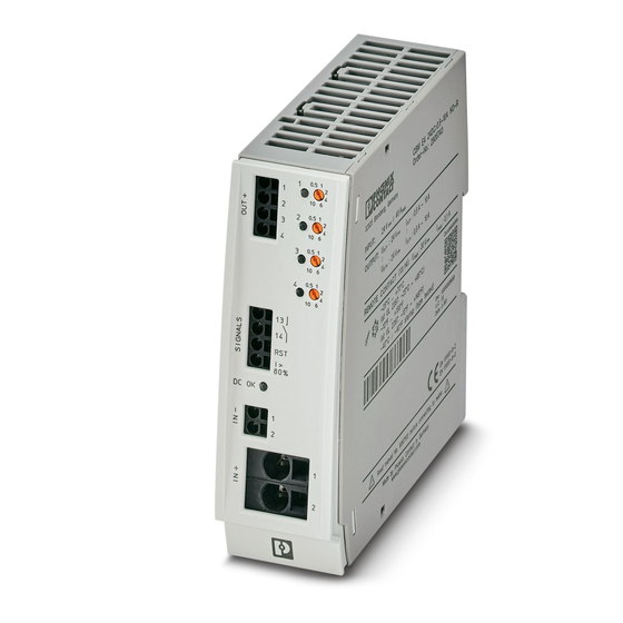
2. Composants du disjoncteur d'appareils ()
1
Sorties protégées
4
Alimentation 24 V DC
2
Signaux
5
Bouton LED de canal
3
Bouton LED « DC OK »
6
Sélecteur de courant
3. Montage
• Monter l'appareil à l'horizontale. Les fentes d'aération doivent être dirigées vers le haut et vers le bas. Afin
de garantir le refroidissement par convection, maintenir une distance minimum de 30 mm en haut et en bas.
( - )
4. Raccordement ()
Pour respecter l'homologation UL, utiliser des câbles en cuivre conçus pour des températures de service
> 90 °C.
• Dimensionner les câbles en fonction du courant d'entrée/sortie maximum.
• Raccorder impérativement le pôle Moins à la borne IN- afin de garantir l'auto-alimentation.
Pour la version 8 canaux :
• Raccorder les deux blocs de jonction d'entrée IN+ 1 et 2 pour que l'alimentation s'effectue avec 40 A.
4.1 Blocs de jonction Push-in
• Insérer le conducteur dans le bloc de jonction.
• Insérer un tournevis dans l'orifice d'ouverture pour libérer à nouveau le conducteur.
5. Configuration
REMARQUE :
Par défaut, tous les canaux sont désactivés et réglés sur 0,5 A.
• Programmer les intensités nominales lors de la mise en service.
5.1 Utilisation
REMARQUE :
– L'activation et la désactivation du canal s'effectuent à l'aide du bouton LED de canal.
– Lors de l'activation suivante, les valeurs du courant réglées en dernier sont reprises.
6. Programmation
• Appuyer sur le bouton LED correspondant pour activer le canal.
• Régler l'intensité nominale nécessaire via le sélecteur de courant. La LED du canal commence à clignoter
en vert.
• Appuyer sur le bouton LED du canal pendant 1 seconde pour enregistrer la nouvelle valeur d'intensité.
REMARQUE : Première programmation
Lorsque le canal a été activé, il arrive qu'il se désactive et la LED clignote alors en rouge.
– Régler l'intensité nominale via le sélecteur de courant à l'état désactivé. La LED clignote à présent en
rouge/vert.
– Appuyer sur le bouton LED pendant 1 seconde pour enregistrer la nouvelle valeur d'intensité.
REMARQUE : Assistant intensité nominale
• Programmer le canal sur 10 A.
• Mettre l'installation en service de sorte que le courant d'installation actuel circule.
• Abaisser pas à pas la valeur réglée du sélecteur de courant pour approcher la valeur actuelle du cou-
rant circulant dans l'installation et trouver ainsi la valeur de réglage adéquate du canal. La LED du
canal concerné clignote en vert.
Si la LED du canal concerné se met à clignoter en jaune/vert/, cela signifie que la valeur de réglage
choisie pour le courant circulant dans l'installation est insuffisante. Régler à nouveau le sélecteur de
courant d'une position vers le haut.
• Appuyer sur le bouton LED du canal pendant 1 seconde pour enregistrer la nouvelle valeur d'inten-
sité.
ENGLISH
Multi-channel electronic device circuit breaker
– Adjustable to the levels of 0.5 A, 1 A, 2 A, 4 A, 6 A, and 10 A
– With current limitation
– 4 or 8-channel
– The circuit breaker is a built-in device
NOTE:
The feed-in power supply must have electrical isolation between the primary and secondary circuit. The
devices can be used up to a maximum of 30 V DC.
1. Safety notes
For use in Degree of Pollution Environmental 2.
• Do not exceed the maximum input/output current of 80 A. Use a current-limited source (e.g., TRIO POWER)
or suitable fuse.
WARNING:
Installation and startup may only be carried out by qualified personnel. The relevant country-specific reg-
ulations must be observed.
WARNING: Risk of electric shock and fire
Check the device for external damage before installation. If the device is defective, it must not be used.
1.1 UL notes
– This equipment is an open-type device meant to be installed in an enclosure suitable for the environment
that is only accessible with the use of a tool.
– Suitable for use in class I, division 2, group A, B, C and D hazardous locations, or nonhazardous locations
only.
WARNING: Explosion hazard
Do not disconnect equipment while the circuit is live or unless the area is known to be free of ignitable
concentrations.
2. Components of the device circuit breaker ()
1
Protected outputs
4
24 V DC supply
2
Signals
5
Channel LED button
3
Channel LED "DC OK" button
6
Power selection switch
3. Mounting
• Mount the device horizontally. The ventilation slots should be oriented upward or downward. Maintain a min-
imum distance of 30 mm on the top and bottom to ensure convection cooling. ( - )
4. Connecting ()
In order to comply with UL approval, use copper cables that are designed for operating tempera-
tures > 90°C.
• Ensure cables are correctly sized for the maximum input/output current.
• It is imperative to connect the negative pole to the IN- terminal to ensure self-supply.
For 8-channel versions:
• Connect the two input terminals IN+ 1 and 2 to supply 40 A.
4.1 Push-in terminal blocks
• To connect the conductor, simply insert it into the terminal.
• Press a screwdriver into the actuation shaft to loosen the conductor again.
5. Configuration
NOTE:
All channels are switched off and set to 0.5 A at the factory.
• Program the desired nominal current during startup.
5.1 Operation
NOTE:
– The channel can be switched on and off via the channel LED button.
– The most recent current value settings are restored when the device is switched on again.
6. Programming
• Switch the channel on by pressing the associated LED button.
• Set the necessary nominal current via the current selection switch. The channel LED starts to blink green.
• Press the channel LED button for 1 second to store the new current value.
NOTE: initial programming
After the channel has been switched on, it may occur that the channel shuts off and the LED blinks red.
– Set the nominal current via the current selection switch while it is switched off. The LED now blinks
red/green.
– Press the LED button for 1 second to store the new current value.
NOTE: nominal current assistant
• Program the channel to 10 A.
• Activate the system so that the current system current flows.
• Turn the current selection switch down step-by-step so that it approaches the system current that is
currently flowing, in order to find the appropriate setting for the channel. The channel LED flashes
green in the process.
If the channel LED changes and starts to flash yellow/green, the selected setting is too low for the sys-
tem current that is currently flowing. Turn the current selection switch back to a higher setting.
• Press the channel LED button for 1 second to store the new current value.
DEUTSCH
Mehrkanalige elektronische Geräteschutzschalter
– Einstellbar in den Stufen 0,5 A, 1 A, 2 A, 4 A, 6 A und 10 A
– Mit Strombegrenzung
– 4- bzw. 8-kanalig
– Der Schutzschalter ist ein Einbaugerät
ACHTUNG:
Die einspeisende Stromversorgung muss über eine galvanische Trennung zwischen Primär- und Se-
kundärstromkreis verfügen. Die Geräte sind bis maximal 30 V DC einsetzbar.
1. Sicherheitshinweise
Zur Verwendung in Räumen und Umgebungen bis Verschmutzungsgrad 2.
• Max. Eingangs-/Ausgangsstrom von 80 A nicht überschreiten. Strombegrenzte Quelle (z. B. TRIO POW-
ER) oder geeignete Sicherung verwenden.
WARNUNG:
Die Installation und Inbetriebnahme darf nur von entsprechend qualifiziertem Fachpersonal durchge-
führt werden. Dabei sind die jeweiligen landesspezifischen Vorschriften einzuhalten.
WARNUNG: Gefahr durch elektrischen Schlag und Brandgefahr
Prüfen Sie vor der Installation das Gerät auf äußere Beschädigung. Wenn das Gerät defekt ist, darf es
nicht verwendet werden.
1.1 UL-Hinweise
– Bei diesem Gerät handelt es sich um ein offenes Gerät (Open-Type-Gerät), das in einem Gehäuse installiert
werden muss, das für die Umgebung geeignet und nur mithilfe eines Werkzeugs zugänglich ist.
– Geeignet für den Einsatz in Class I, Division 2, Gruppe A, B, C und D in explosionsgefährdeten Bereichen
oder nur in nicht explosionsgefährdeten Bereichen.
WARNUNG: Explosionsgefahr
Schalten Sie das Gerät nicht unter Spannung ab, es sei denn der Bereich enthält keine zündfähigen
Konzentrationen.
2. Bestandteile des Geräteschutzschalters ()
1
geschützte Ausgänge
4
Einspeisung 24 V DC
2
Signale
5
Kanal-LED-Taster
3
LED-Taster "DC OK"
6
Stromwahlschalter
3. Montieren
• Montieren Sie das Gerät waagerecht. Die Lüftungsschlitze sollen nach oben und unten gerichtet sein. Um
die Konvektionskühlung sicher zu stellen, halten Sie einen Mindestabstand von 30 mm nach oben und un-
ten ein. ( - )
4. Anschließen ()
Verwenden Sie zur Einhaltung der UL-Approbation Kupferkabel, die für Betriebstemperaturen > 90 °C
ausgelegt sind.
• Dimensionieren Sie die Leitungen dem maximalen Eingangs- bzw. Ausgangsstrom entsprechend.
• Schließen Sie zwingend den Minuspol an die Klemme IN- an, um die Eigenversorgung sicher zu stellen.
Für 8-Kanal-Variante:
• Schließen Sie beide Eingangsklemmen IN+ 1 und 2 an, um 40 A einzuspeisen.
4.1 Push-in-Klemmen
• Stecken Sie, zum Verbinden, den Leiter einfach in die Klemme ein.
• Um den Leiter wieder zu lösen, drücken Sie einen Schraubendreher in den Betätigungsschacht.
5. Konfigurieren
HINWEIS:
Alle Kanäle sind werksseitig ausgeschaltet und auf 0,5 A eingestellt.
• Programmieren Sie bei Inbetriebnahme die gewünschten Nennströme.
5.1 Bedienung
HINWEIS:
– Ein- und Ausschalten des Kanals ist über den Kanal-LED-Taster möglich.
– Bei erneutem Einschalten werden die zuletzt eingestellten Stromwerte wieder eingenommen.
6. Programmieren
• Schalten Sie den Kanal durch Drücken des zugehörigen LED-Tasters ein.
• Stellen Sie den erforderlichen Nennstrom über den Stromwahlschalter ein. Die Kanal-LED fängt an grün zu
blinken.
• Drücken Sie den Kanal-LED-Taster 1 Sekunde, um den neuen Stromwert zu speichern.
HINWEIS: Erstprogrammierung
Nach dem Einschalten des Kanals kann es dazu kommen, dass der Kanal abschaltet und die LED rot
blinkt.
– Stellen Sie den Nennstrom über den Stromwahlschalter im ausgeschalteten Zustand ein. Die LED
blinkt nun rot/grün.
– Drücken Sie den LED-Taster 1 Sekunde, um den neuen Stromwert zu speichern.
HINWEIS: Nennstrom-Assistent
• Programmieren Sie den Kanal auf 10 A.
• Nehmen Sie die Anlage in Betrieb, sodass der aktuelle Anlagenstrom fließt.
• Drehen Sie den Stromwahlschalter schrittweise herunter, um sich dem aktuell fließenden Anlagen-
strom zu nähern und somit den geeigneten Einstellwert des Kanals zu finden. Hierbei blinkt die Ka-
nal-LED grün.
Wenn die Kanal-LED nach gelb/grün blinkend wechselt, so ist der gewählte Einstellwert für den ak-
tuell fließenden Anlagenstrom zu gering. Drehen Sie den Stromwahlschalter wieder um eine Stellung
hoch.
• Drücken Sie den Kanal-LED-Taster 1 Sekunde, um den neuen Stromwert zu speichern.
PHOENIX CONTACT GmbH & Co. KG
Flachsmarktstraße 8, 32825 Blomberg, Germany
Fax +49-(0)5235-341200, Phone +49-(0)5235-300
phoenixcontact.com
MNR 9067103 - 04
DE
Betriebsanleitung für den Elektroinstallateur
EN
Operating instructions for electrical personnel
FR
Manuel d'utilisation pour l'électricien
CBM E4 24DC/0.5-10A NO-R
CBM E8 24DC/0.5-10A NO-R
1
1
1
2
2
3
4
3
5
6
7
4
2
8
5
13
14
6
RST
3
I >
80%
7
DC OK
8
1
2
4
1
2
3
4
5
6
7
8
13
14
RST
I >
80%
DC OK
1
2
L [mm]
AWG
+
[mm²]
OUT+
0,2-2,5
SIGNALS
24-12
10
IN-
0,75-16
IN+
20-4
18
41
121
1
0,5
1
1
2
4
10
6
2
2
0,5
1
3
2
4
10
6
4
3
0,5
5
1
2
4
10
6
6
7
4
0,5
1
2
4
8
10
6
5
0,5
1
13
2
4
10
6
14
6
0,5
1
RST
2
4
I >
10
6
80%
7
0,5
1
2
DC OK
10
6
4
1
8
0,5
1
2
4
2
10
6
1
2
© PHOENIX CONTACT 2020
2020-03-30
2905743
2905744
5
0,5
1
2
4
10
6
0,5
1
2
6
4
10
6
0,5
1
2
4
10
6
0,5
1
2
4
10
6
0,5
1
2
4
10
6
0,5
1
2
4
10
6
0,5
1
2
4
10
6
0,5
1
2
4
10
6
1
2
1
0,5
1
2
4
10
6
2
0,5
1
2
4
10
6
3
0,5
1
2
10
6
4
4
0,5
1
2
4
10
6
5
0,5
1
2
4
10
6
6
0,5
1
2
4
10
6
7
0,5
1
2
4
10
6
8
0,5
1
2
4
10
6
1
2
Publicidad

Manuales relacionados para Phoenix Contact CBM E4 24DC/0.5-10A NO-R


Resumen de contenidos para Phoenix Contact CBM E4 24DC/0.5-10A NO-R
- Página 1 PHOENIX CONTACT GmbH & Co. KG FRANÇAIS ENGLISH DEUTSCH Flachsmarktstraße 8, 32825 Blomberg, Germany Disjoncteurs électroniques multicanaux Multi-channel electronic device circuit breaker Mehrkanalige elektronische Geräteschutzschalter Fax +49-(0)5235-341200, Phone +49-(0)5235-300 phoenixcontact.com MNR 9067103 - 04 2020-03-30 – Réglables aux paliers 0,5 A, 1 A, 2 A, 4 A, 6 A et 10 A –...
- Página 2 Le disjoncteur ne requiert aucun entretien. Seul le constructeur est autorisé à effectuer des réparations. Caractéristiques techniques Technical data Technische Daten Type Type CBM E4 24DC/0.5-10A NO-R CBM E8 24DC/0.5-10A NO-R Tension de service Operating voltage Betriebsspannung 18 V DC ... 30 V DC Courant de référence I...
- Página 3 PHOENIX CONTACT GmbH & Co. KG PORTUGUÊS ESPAÑOL ITALIANO Flachsmarktstraße 8, 32825 Blomberg, Germany Disjuntores de proteção de equipamentos eletrônicos de canais múltiplos Interruptores electrónicos de varios canales para protección de dispositi- Interruttori di protezione elettronici multicanale Fax +49-(0)5235-341200, Phone +49-(0)5235-300 phoenixcontact.com...
- Página 4 El interruptor de protección está libre de mantenimiento. Solamente el fabricante podrá realizar reparaciones. Dados técnicos Datos técnicos Dati tecnici Tipo Tipo Tipo CBM E4 24DC/0.5-10A NO-R CBM E8 24DC/0.5-10A NO-R Tensão operacional Tensión de servicio Tensione di esercizio 18 V DC ... 30 V DC Corrente nominal I Corriente asignada I Corr.
- Página 5 中文 PHOENIX CONTACT GmbH & Co. KG POLSKI РУССКИЙ TÜRKÇE Flachsmarktstraße 8, 32825 Blomberg, Germany 多通道电子设备断路器 Wielokanałowe elektroniczne wyłączniki urządzeń Многоканальные электронные автоматические Çok kanallı elektronik cihaz devre kesici Fax +49-(0)5235-341200, Phone +49-(0)5235-300 phoenixcontact.com MNR 9067103 - 04 2020-03-30 – 可根据 0.5 A、1 A、2 A、4 A、6 A 和 10 A 水平进行调节...
- Página 6 Автоматический выключатель не требует техобслуживания. Все ремонтные работы должны выполняться компанией-изготовителем. 技术数据 Dane techniczne Технические характеристики Teknik veriler 类型 Тип CBM E4 24DC/0.5-10A NO-R CBM E8 24DC/0.5-10A NO-R 工作电压 Napięcie robocze Рабочее напряжение Çalışma gerilimi 18 V DC ... 30 V DC 标称工作电流 I Prąd znamionowy I...