Tabla de contenido
Publicidad
Idiomas disponibles
Idiomas disponibles
Enlaces rápidos
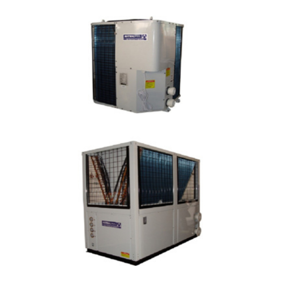
MODELS
AHP020/CHPC020
AHP100/CHPC100
AHP400/CHPC400
Nos reservamos el derecho de cambiar total o parcialmente las características de nuestros artículos o contenido de este documento sin previo aviso.
Nous nous réservons le droit de modifier totalement oru en partie les caracteristiques de nos articles ou le contenu de ce document san pré avis.
Wir behalten uns das recht vor die eigenschaften unserer produkte oder den inhalt diese prospektes teilweise oder wollstanding, ohne vorherige benachichtigung su andern.
Ci riservamo il diritto di cambiare totalemente o parzialmente le caratteristiche tecniche dei nostri prodotti ed il contenuto di questo documento senza nessum preavviso.
Wij behouden ons het recht voor geheel of gedeeltelijk de kenmerken van onze artikelen of de inhouk van deze handleiding zonder voorafgaand bericht te wjzigen.
Reservamo-nos no dereito de alterar, total ou parcialmente as caracteristicas os nossos artigos ou o conteúdo deste documento sem aviso prévio.
V. 2011 - 06 - 09 R407C
AHP030/CHPC030
AHP130/CHPC130
AHP500/CHPC400
V-HEAT HEAT PUMP
Instruction manual
BOMBA DE CALOR PARA PISCINA V-HEAT
Manual de instrucciones
POMPE À CHALEUR V-HEAT
Manuel d´instructions
WÄRMEPUMPE V-HEAT
Bedienungsanleitung
POMPA DI CALORE V-HEAT
Manuale delle instruzioni
BOMBA DE CALOR V-HEAT
Manual de instruções
WARMTEPOMP V-HEAT
Handleiding met instructies
We reserve to change all of part of the articles or contents of this document, without prior notice.
AHP050/CHPC050
AHP200/CHPC200
www.astralpool.com
AHP060/CHPC060
AHP250/CHPC250
Publicidad
Tabla de contenido

Manuales relacionados para Astralpool V-HEAT Serie


Resumen de contenidos para Astralpool V-HEAT Serie
- Página 1 MODELS AHP020/CHPC020 AHP030/CHPC030 AHP050/CHPC050 AHP060/CHPC060 AHP100/CHPC100 AHP130/CHPC130 AHP200/CHPC200 AHP250/CHPC250 AHP400/CHPC400 AHP500/CHPC400 V-HEAT HEAT PUMP Instruction manual BOMBA DE CALOR PARA PISCINA V-HEAT Manual de instrucciones POMPE À CHALEUR V-HEAT Manuel d´instructions WÄRMEPUMPE V-HEAT Bedienungsanleitung POMPA DI CALORE V-HEAT Manuale delle instruzioni BOMBA DE CALOR V-HEAT Manual de instruções WARMTEPOMP V-HEAT...
- Página 2 © ASTRALPOOL 2018. ALL RIGHTS RESERVED. CONFIDENTIAL AND PROPRIETARY DOCUMENT. Page 2 of 72...
- Página 3 BOMBA DE CALOR V-HEAT - SÉRIES V-HEAT • SISTEMA AIRE/AGUA POMPE À CHALEUR V-HEAT - SÉRIES V-HEAT • SYSTÈME AIR/EAU V-HEAT SERIE • LUFT-WASSER-SYSTEM WÄRMEPUMPE V-HEAT POMPA DI CALORE V-HEAT - SERIE V-HEAT • SISTEMA ARIA/ACQUA BOMBA DE CALOR V-HEAT SÉRIES V-HEAT •...
-
Página 4: Tabla De Contenido
TABLE OF CONTENTS INTRODUCTION ....................... 7 DESCRIPTION OF THE HEAT PUMP ................7 Technical Data ........................7 PRECAUTIONS FOR USE AND CONDITIONS OF USE ..........9 Safety Instructions ......................9 Installation Conditions ...................... 10 START-UP OF THE HEAT PUMP ................... 11 Installation Rules ...................... - Página 5 INDICE DE CONTENIDOS INTRODUCCIÓN ......................39 DESCRIPCIÓN DE LA BOMBA DE CALOR ..............39 Características técnicas ....................39 PRECAUCIONES DE EMPLEO Y CONDICIONES DE USO ........... 41 Instrucciones de seguridad ....................41 Condiciones de instalación ....................42 PUESTA EN MARCHA DE LA BC ................... 43 Reglas de instalación .......................
- Página 6 ENGLISH V-HEAT SERIES · AIR/WATER SYSTEM EIGHT ESSENTIAL POINTS (Read carefully before start-up) Check unit condition upon receipt. If the unit is damaged or if the shipment is not complete, make a note in the delivery note and send an immediate complaint to the company that forwarded the shipment. It is essential that the installer receives the installation manual.
-
Página 7: Introduction
ENGLISH V-HEAT SERIES · AIR/WATER SYSTEM 1 INTRODUCTION Thank you for acquiring the heat pump for heating outdoor swimming pools. The experience our company has gained during more than 25 years in the world of air conditioning of swimming pools has been put to your service in this product, in which we also incorporate the technical breakthroughs that turn this heat pump into the equipment that can solve once and for all the air conditioning of your swimming pool, extending thus the length of your bathing season. - Página 8 V-HEAT SERIES · AIR/WATER SYSTEM ENGLISH MODELS BTU/H Heating W Out Heating W In BTU/H Cooling W Out Cooling W In AHP020/ 30.000 8.800 1.800 24.000 7.000 2.300 CHPC020 AHP030/ 2,5HP 44.000 13.000 2.650 30.000 8.800 2.850 CHPC030 AHP050/ 72.000 21.000 4.600 49.500...
-
Página 9: Precautions For Use And Conditions Of Use
ENGLISH V-HEAT SERIES · AIR/WATER SYSTEM 3 PRECAUTIONS FOR USE AND CONDITIONS OF USE 3.1 Safety Instructions Read the safety instructions prior to any manipulation: ATTENTION Any incorrect manipulation may cause an important risk that could involve deadly injuries. WARNING Any incorrect manipulation may cause serious damages to the user and the unit. -
Página 10: Installation Conditions
ENGLISH V-HEAT SERIES · AIR/WATER SYSTEM 3.2 Installation Conditions Do not install the unit near a flammable gas source, since a gas leak may occur and cause an explosion. According to the place where the unit must be Condensers must have been completely drained. installed (humid place, etc.), install electrical Otherwise, the water could leak out of the unit and protection by a 30 mA differential circuit breaker. -
Página 11: Start-Up Of The Heat Pump
ENGLISH V-HEAT SERIES · AIR/WATER SYSTEM 4 START-UP OF THE HEAT PUMP 4.1 Installation Rules It is necessary to determine the unit location according to certain criteria: · The unit must be secured on a hard base (concrete or hard steel frame type) and must be protected from flood risks. ·... -
Página 12: Electrical Connection
ENGLISH V-HEAT SERIES · AIR/WATER SYSTEM If it is not possible to install the feeder 25cm below the water discharge of the heat pump a siphon should be installed. For additional security, a check valve should also be installed to prevent the chemical product from returning to the pump when water circulation is interrupted. - Página 13 ENGLISH V-HEAT SERIES · AIR/WATER SYSTEM The electrical installation should be done by qualified professionals, keeping in mind the following points: Connect the equipment following the wiring diagram included in this manual. Place a U-curve thermal-magnetic circuit breaker in the general power connection to protect the line in the case of a short in the circuit.
-
Página 14: Diagrams
ENGLISH V-HEAT SERIES · AIR/WATER SYSTEM 4.4 Diagrams 4.4.1 Electrical diagram for single-phase installation AHP020/030-CHPC020/030 © ASTRALPOOL 2018. ALL RIGHTS RESERVED. CONFIDENTIAL AND PROPRIETARY DOCUMENT. Page 14 of 72... -
Página 15: Electrical Diagrams For Three-Phase Installation
ENGLISH V-HEAT SERIES · AIR/WATER SYSTEM 4.4.2 Electrical diagram for three-phase installation AHP050-CHPC050 © ASTRALPOOL 2018. ALL RIGHTS RESERVED. CONFIDENTIAL AND PROPRIETARY DOCUMENT. Page 15 of 72... - Página 16 ENGLISH V-HEAT SERIES · AIR/WATER SYSTEM AHP060-CHPC060 © ASTRALPOOL 2018. ALL RIGHTS RESERVED. CONFIDENTIAL AND PROPRIETARY DOCUMENT. Page 16 of 72...
- Página 17 ENGLISH V-HEAT SERIES · AIR/WATER SYSTEM AHP100/130-CHPC100/130 © ASTRALPOOL 2018. ALL RIGHTS RESERVED. CONFIDENTIAL AND PROPRIETARY DOCUMENT. Page 17 of 72...
- Página 18 ENGLISH V-HEAT SERIES · AIR/WATER SYSTEM AHP200-CHPC200 © ASTRALPOOL 2018. ALL RIGHTS RESERVED. CONFIDENTIAL AND PROPRIETARY DOCUMENT. Page 18 of 72...
- Página 19 ENGLISH V-HEAT SERIES · AIR/WATER SYSTEM AHP250-CHPC250 © ASTRALPOOL 2018. ALL RIGHTS RESERVED. CONFIDENTIAL AND PROPRIETARY DOCUMENT. Page 19 of 72...
- Página 20 ENGLISH V-HEAT SERIES · AIR/WATER SYSTEM AHP400-CHPC400 © ASTRALPOOL 2018. ALL RIGHTS RESERVED. CONFIDENTIAL AND PROPRIETARY DOCUMENT. Page 20 of 72...
- Página 21 ENGLISH V-HEAT SERIES · AIR/WATER SYSTEM AHP500-CHPC500 © ASTRALPOOL 2018. ALL RIGHTS RESERVED. CONFIDENTIAL AND PROPRIETARY DOCUMENT. Page 21 of 72...
- Página 22 ENGLISH V-HEAT SERIES · AIR/WATER SYSTEM CHILLER300 No. Symbol Meaning HEAT Alarm output(220-240VAC) PUMP Water pump (220-240VAC) Fan motor (220-240VAC) VAL2 Solenoid valve (220-240VAC) VAL1 4Way valve of system1 (220-240VAC) COMP2 Compressor of system2 (220-240VAC) COMP1 Compressor of system1 (220-240VAC) AC-L Live wire AV-N...
- Página 23 ENGLISH V-HEAT SERIES · AIR/WATER SYSTEM PROTECT300 No. symbol Meaning High2 GND High pressure protection for system2(normal close) Low2 GND Low pressure protection for system2(normal close) High1 GND High pressure protection for system1(normal close) Low1 GND Low pressure protection for system1(mortal close) SYS GND 12V Protection signal Current setting (handset) COMP2...
- Página 24 ENGLISH V-HEAT SERIES · AIR/WATER SYSTEM © ASTRALPOOL 2018. ALL RIGHTS RESERVED. CONFIDENTIAL AND PROPRIETARY DOCUMENT. Page 24 of 72...
-
Página 25: Description And Operation Of The Controller
ENGLISH V-HEAT SERIES · AIR/WATER SYSTEM 5 DESCRIPTION AND OPERATION OF THE CONTROLLER Standby status-press “SET” button to enter operation parameter setting interface. Press “SET” again to start setting (parameter from 00 to 09. See Operation Parameter’s Table). ▲ ▲ ▲ ▲ ▲... - Página 26 ENGLISH V-HEAT SERIES · AIR/WATER SYSTEM Parameter 02. Total working time of the compressor after defrosting Parameter 03. Terms of defrosting start (-30-0ºC) Default setting = -7ºC Parameter 04. Terms of defrosting end (0-30ºC) Default setting = 13ºC Parameter 05. Maximum time of defrosting (0-15 min) Default setting = 8 min Parameter 06.
- Página 27 ENGLISH V-HEAT SERIES · AIR/WATER SYSTEM Parameter 08. Selection Mode 0 = Cooling only 1 = Cooling and heating 2 = Auxiliary electric heating 3 = Heating only Parameter 09. Water Pump Control 0 = Always open 1 = 60 seconds start before compressors starting, 30 seconds stop after compressors stopping How to choose the Mode Cooling Mode...
- Página 28 ENGLISH V-HEAT SERIES · AIR/WATER SYSTEM Operation Data Settings The unit’s operation data can be set on the whire controller. Please set according the below table: Digit Meaning Range Default Adjust (yes/no) Return water temp. 8-28 ℃ Setting(cooling mode) Return water temp. 15-40 ℃...
-
Página 29: Start-Up Procedure For The Unit
ENGLISH V-HEAT SERIES · AIR/WATER SYSTEM 6 START-UP PROCEDURE FOR THE UNIT Operating requirements for the heat pump · The outdoor temperature must be higher than +8 ºC. · The heat pump is provided with a defrost thermostat that guarantees the compressor shutdown and the operation of the defrost system. -
Página 30: Hibernation Procedure
ENGLISH V-HEAT SERIES · AIR/WATER SYSTEM 7 HIBERNATION PROCEDURE 1. Switch off the filtering pump. 2. Turn off the by-pass valves. 3. Open completely the drain cock of the condensers. 4. Drain the exchanger to protect it from ice. 5. Once drained part of the condenser, close the drain cock. 6. -
Página 31: Electrical Panel
ENGLISH V-HEAT SERIES · AIR/WATER SYSTEM CONDENSER: Install chemical feeders “downstream” from the heat pump, as far away and at a lower height. The feeder should never be installed near the intake of the purification pump as this will damage the condenser. NEVER introduce concentrated chemical products in the pool skimmers as this will damage the Titanium condenser. - Página 32 ENGLISH V-HEAT SERIES · AIR/WATER SYSTEM Refrigerant Gas Charge: The equipment uses R407C class refrigerant. The gas taken from the refrigerant bottle must be introduced in the low- pressure circuit by means of a charger (expansion system). After having discharged the cooling circuit, and after having installed the charger and connected the flexible tubes of the gauge to the high and low-pressure circuits, we can proceed with the charge: 1.- High and low pressure switches 2.- Low pressure circuit (blue).
-
Página 33: Troubleshooting Guide
ENGLISH V-HEAT SERIES · AIR/WATER SYSTEM The R407C Gas: ⋅ The R407C is a NONFLAMMABLE gas; it has no flash point, and so is not subjected to the rules and regulations of the transportation of inflammable gases. ⋅ The R407C does not irritate the skin, eyes or mucous membranes and does not produce and side-effects. ⋅... -
Página 34: General Instructions
ENGLISH V-HEAT SERIES · AIR/WATER SYSTEM filter-drier, expansion valve, etc. and replace if necessary. Verify that the equipment is powerful enough for the existing thermal conditions. Excessive noise: The fastening screws of the compressor or fan are loose: Tighten all the fastening elements. ⋅... - Página 35 ENGLISH V-HEAT SERIES · AIR/WATER SYSTEM Malfunction Reason Resolution LCD Controller Water inlet temp. sensor failure PP01 The sensor is open or short circuit Check or change the sensor Water outlet temp. sensor PP02 The sensor is open or short circuit Check or change the sensor failure Cool1 sensor1 failure...
-
Página 36: Product Recycling
ENGLISH V-HEAT SERIES · AIR/WATER SYSTEM 11 PRODUCT RECYCLING This unit has a refrigeration gas in liquid state and electrical components. When the heat pump reaches the end of its service life, it should be dismantled by an authorised company or it should be sent to the place selected by the local authorities. -
Página 37: Warranty Coverage
ENGLISH V-HEAT SERIES · AIR/WATER SYSTEM WARRANTY CERTIFICATE 1. WARRANTY COVERAGE 1.1 In accordance with these provisions, the salesman guarantees that the product corresponding to this warranty (“the product”) does not present any non-conformance at the moment of its delivery. 1.2 The warranty period of the product is of two (2) years and it will take effect as of the time of delivery to the buyer. - Página 38 ESPAÑOL SERIES V-HEAT · SISTEMA AIRE/AGUA LOS 8 PUNTOS ESENCIALES. (Leer atentamente antes de puesta en marcha) Verificar el estado de la máquina a su recepción. Si la unidad está dañada o si el envío no está completo, anotar en el albarán de entrega y enviar una reclamación inmediata a la compañía que realizó...
-
Página 39: Introducción
ESPAÑOL SERIES V-HEAT · SISTEMA AIRE/AGUA 1 INTRODUCCIÓN Gracias por adquirir la bomba de calor para calentamiento de piscinas al aire libre. La experiencia acumulada por nuestra compañía durante más de 25 años en el mundo de la climatización de piscinas ha sido puesta a su servicio en este producto, en el que además incorporamos los avances técnicos que hacen de su bomba de calor el equipo que puede solucionar de forma definitiva la climatización de su piscina, y con ello la prolongación de su temporada anual de baño. - Página 40 ESPAÑOL SERIES V-HEAT · SISTEMA AIRE/AGUA Potencia Cedida Potencia Absorbida Potencia Cedida Potencia Absorvida MODELOS BTU/H COP BTU/H Calefacción W Calefacción W Enfriando W Enfriando W AHP020/ 30.000 8.800 1.800 4,9 24.000 7.000 2.300 CHPC020 AHP030/ 2,5HP 44.000 13.000 2.650 4.9 30.000 8.800 2.850...
-
Página 41: Precauciones De Empleo Y Condiciones De Uso
ESPAÑOL SERIES V-HEAT · SISTEMA AIRE/AGUA 3 PRECAUCIONES DE EMPLEO Y CONDICIONES DE USO 3.1 Instrucciones de seguridad Lea las instrucciones de seguridad antes de cualquier uso: ATENCIÓN Cualquier manipulación incorrecta puede causar un riesgo importante que puede comportar la muerte. ADVERTENCIA Cualquier manipulación incorrecta puede provocar serios daños al usuario y al aparato. -
Página 42: Condiciones De Instalación
ESPAÑOL SERIES V-HEAT · SISTEMA AIRE/AGUA 3.2 Condiciones de instalación No instale la unidad cerca de una fuente de gas inflamable, ya que podría producirse una fuga de gas y provocar una explosión. ADVERTENCIA No ponga nada encima de la unidad. Podría No deje una instalación dañada. -
Página 43: Puesta En Marcha De La Bc
ESPAÑOL SERIES V-HEAT · SISTEMA AIRE/AGUA 4 PUESTA EN MARCHA DE LA BC 4.1 Reglas de instalación Es necesario determinar el emplazamiento del aparato según determinados criterios: · El aparato debe fijarse sobre una base dura (de tipo de hormigón o de chasis de acero duro) y debe estar protegida de los riesgos de inundación. -
Página 44: Conexión Eléctrica
ESPAÑOL SERIES V-HEAT · SISTEMA AIRE/AGUA Siempre que no sea posible disponer la entrada del sistema dosificador 25 cm por debajo de la salida de agua de la bomba de calor, se deberá instalar un sifón, y como seguridad añadida una válvula antirretorno que impida el retorno de producto químico a la bomba cuando la circulación de agua se interrumpa. - Página 45 ESPAÑOL SERIES V-HEAT · SISTEMA AIRE/AGUA La acometida eléctrica deberá realizarse por el instalador teniendo en cuenta los siguientes puntos: Realizar la conexión según el esquema eléctrico incluido en este manual. Colocar en la acometida general de fuerza un magnetotérmico curva U, que protegerá la línea en caso de cortocircuito.
-
Página 46: Esquemas
ESPAÑOL SERIES V-HEAT · SISTEMA AIRE/AGUA 4.4 Esquemas 4.4.1 Esquemas eléctricos monofásicos AHP020/030-CHPC020/030 © ASTRALPOOL 2018. ALL RIGHTS RESERVED. CONFIDENTIAL AND PROPRIETARY DOCUMENT. Page 46 of 72... -
Página 47: Esquemas Eléctricos Trifásicos
ESPAÑOL SERIES V-HEAT · SISTEMA AIRE/AGUA 4.4.2 Esquemas eléctricos trifásicos AHP050-CHPC050 © ASTRALPOOL 2018. ALL RIGHTS RESERVED. CONFIDENTIAL AND PROPRIETARY DOCUMENT. Page 47 of 72... - Página 48 ESPAÑOL SERIES V-HEAT · SISTEMA AIRE/AGUA AHP060-CHPC060 © ASTRALPOOL 2018. ALL RIGHTS RESERVED. CONFIDENTIAL AND PROPRIETARY DOCUMENT. Page 48 of 72...
- Página 49 ESPAÑOL SERIES V-HEAT · SISTEMA AIRE/AGUA AHP100/130-CHPC100/130 © ASTRALPOOL 2018. ALL RIGHTS RESERVED. CONFIDENTIAL AND PROPRIETARY DOCUMENT. Page 49 of 72...
- Página 50 ESPAÑOL SERIES V-HEAT · SISTEMA AIRE/AGUA AHP200-CHPC200 © ASTRALPOOL 2018. ALL RIGHTS RESERVED. CONFIDENTIAL AND PROPRIETARY DOCUMENT. Page 50 of 72...
- Página 51 ESPAÑOL SERIES V-HEAT · SISTEMA AIRE/AGUA AHP250-CHPC250 © ASTRALPOOL 2018. ALL RIGHTS RESERVED. CONFIDENTIAL AND PROPRIETARY DOCUMENT. Page 51 of 72...
- Página 52 ESPAÑOL SERIES V-HEAT · SISTEMA AIRE/AGUA AHP400-CHPC400 © ASTRALPOOL 2018. ALL RIGHTS RESERVED. CONFIDENTIAL AND PROPRIETARY DOCUMENT. Page 52 of 72...
- Página 53 ESPAÑOL SERIES V-HEAT · SISTEMA AIRE/AGUA AHP500-CHPC500 © ASTRALPOOL 2018. ALL RIGHTS RESERVED. CONFIDENTIAL AND PROPRIETARY DOCUMENT. Page 53 of 72...
- Página 54 ESPAÑOL SERIES V-HEAT · SISTEMA AIRE/AGUA CHILLER300 Nº Símbolo Significado HEAT Salida Alarma (220-240VAC) PUMP Bomba de Agua (220-240VAC) Motor Ventilador (220-240VAC) VAL2 Válvula Solenide (220-240VAC) VAL1 Válvula 4 Vías Sistema 1 (220-240VAC) COMP2 Compresor Sistema 2 (220-240VAC) COMP1 Compresor Sistema 1 (220-240VAC) AC-L Cable de Línea L AV-N...
- Página 55 ESPAÑOL SERIES V-HEAT · SISTEMA AIRE/AGUA PROTECT300 Nº Símbolo Significado High2 GND Presostato de Alta Presión para Sistema 2 (normalmente cerrado) Low2 GND Presostato de Baja Presión para Sistema 2 (normalmente cerrado) High1 GND Presostato de Alta Presión para Sistema 1 (normalmente cerrado) Low1 GND Presostato de Baja Presión para Sistema 1 (normalmente cerrado) SYS GND 12V Protección de señal...
- Página 56 ESPAÑOL SERIES V-HEAT · SISTEMA AIRE/AGUA © ASTRALPOOL 2018. ALL RIGHTS RESERVED. CONFIDENTIAL AND PROPRIETARY DOCUMENT. Page 56 of 72...
-
Página 57: Descripción Y Funcionamiento Del Regulador De Control
ESPAÑOL SERIES V-HEAT · SISTEMA AIRE/AGUA 5 DESCRIPCIÓN Y FUNCIONAMIENTO DEL REGULADOR DE CONTROL En el modo de espera, presionar el botón “SET” para entrar en el menu de configuración de parámetros. Presionar “SET” otra vez para empezar a configurar los parámetros (desde 00 a 09. Ver Tabla de Parámetros). ▲... - Página 58 ESPAÑOL SERIES V-HEAT · SISTEMA AIRE/AGUA Parámetro 02. Tiempo de funcionamiento del compresor entre desescarches Parámetro 03. Temperatura de comienzo del desescarche (-30-0ºC) Valor por defecto = -7ºC Parámetro 04. Temperatura de final de desescarche (0-30ºC) Valor por defecto = 13ºC Parámetro 05.
- Página 59 ESPAÑOL SERIES V-HEAT · SISTEMA AIRE/AGUA Parámetro 08. Selección de Modo 0 = Enfriar sólo 1 = Enfriar y calentar 2 = Calentamiento eléctrico auxiliar 3 = Calentar sólo Parámetro 09. Control de Depuradora 0 = Siempre encendida 1 = Se arranca 60 segundos antes que los compresores y se apaga 30 segundos después de que lo hagan los compresores.
- Página 60 ESPAÑOL SERIES V-HEAT · SISTEMA AIRE/AGUA Configuración de los parámetros de funcionamiento Los parámetros de funcionamiento de la máquina pueden ser configurados a través del display. A continuación se muestra la Tabla de Parámetros: Parámetro Significado Rango Por defecto Modificable (si/no) Temperatura entrada a la 8-28 27ºC...
-
Página 61: Procedimiento De Puesta En Marcha De La Máquina
ESPAÑOL SERIES V-HEAT · SISTEMA AIRE/AGUA 6 PROCEDIMIENTO DE PUESTA EN MARCHA DE LA MÁQUINA Condición de funcionamiento de la bomba de calor La temperatura exterior debe ser superior a +8 ºC. La bomba de calor está equipada con un termostato de desescarche que asegura la parada del(os) compresor(es) y el funcionamiento del sistema de desescarche. -
Página 62: Procedimiento De Hibernación
ESPAÑOL SERIES V-HEAT · SISTEMA AIRE/AGUA 7 PROCEDIMIENTO DE HIBERNACIÓN Apague la bomba de filtración. Cierre las válvulas del by-pass. Abra completamente la llave de vaciado de los condensadores. Vacíe el intercambiador para preservarlo del hielo. Una vez vaciado parte del condensador, cierre la llave de vaciado. Revise los conectores y las válvulas del by-pass (cerradas) de la bomba de calor para limitar la entrada de cuerpos extraños o agua en el intercambiador. -
Página 63: Condensador
ESPAÑOL SERIES V-HEAT · SISTEMA AIRE/AGUA CONDENSADOR: Instalar los dosificadores de productos químicos “aguas abajo” de la bomba de calor, a una altura inferior a la de la bomba, y siempre lo más lejos posible de la misma. Nunca en la aspiración de la bomba de depuración pues deterioraría el condensador. - Página 64 ESPAÑOL SERIES V-HEAT · SISTEMA AIRE/AGUA Conectar la línea central del puente del manómetro a la botella de R407C por la llave de líquido. Abrir la llave de botella y purgar el trozo de tubería. C. Abrir la válvula de baja presión y la de alta presión. D.
-
Página 65: Averias, Sus Causas Y Soluciones
ESPAÑOL SERIES V-HEAT · SISTEMA AIRE/AGUA 10 AVERIAS, SUS CAUSAS Y SOLUCIONES. Las circunstancias por las que su bomba de calor podría no funcionar se detallan a continuación: El equipo no se pone en marcha: ⋅ Interruptor de maniobra abierto: Comprobar que no hay ningún cortocircuito en el cuadro de maniobra, reparar el posible cortocircuito. -
Página 66: Indicaciones Generales
ESPAÑOL SERIES V-HEAT · SISTEMA AIRE/AGUA INDICACIONES GENERALES - Cualquier intervención en el circuito frigorífico debe realizarse siguiendo las normas de seguridad en vigor: recuperación de fluidos frigoríficos, soldaduras con nitrógeno, etc. - Cualquier intervención de soldadura debe de realizarse por soldadores cualificados. - Para aparatos cargados con R407C ver instrucciones específicas en el manual de utilización. - Página 67 ESPAÑOL SERIES V-HEAT · SISTEMA AIRE/AGUA Fallo Razón Solución Display Fallo sensor temperatura El sensor está desconectado o Comprobar o cambiar el PP01 entrada agua cortocircuitado sensor. Fallo sensor temperatura El sensor está desconectado o Comprobar o cambiar el PP02 salida agua cortocircuitado sensor.
-
Página 68: Reciclaje Del Producto
ESPAÑOL SERIES V-HEAT · SISTEMA AIRE/AGUA 11 RECICLAJE DEL PRODUCTO Esta máquina dispone de un gas frigorífico de estado líquido y de componentes eléctricos. Cuando la bomba de calor finalice su vida útil, deberá ser desmantelada por una empresa habilitada para ello o podrá llevarlo al sitio que destinan las diferentes entidades locales. -
Página 69: Aspectos Generales
SERIES V-HEAT · SISTEMA AIRE/AGUA ESPAÑOL CERTIFICADO DE GARANTÍA 1. ASPECTOS GENERALES 1.1 De acuerdo con estas disposiciones, el vendedor garantiza que el producto correspondiente a esta garantía (“el producto”) no presenta ninguna falta de conformidad en el momento de su entrega. 1.2 El período de garantía para el producto es de dos (2) años, y se calculará... - Página 70 NEDERLANDS SÉRIES V-HEAT · SYSTEEM LUCHT/WATER WE RESERVE THE RIGHT TO CHANGE ALL OR PART OF THE FEATURES OF THE ARTICLES OR CONTENTS OF THIS DOCUMENT, WITHOUT PRIOR NOTICE NOS RESERVAMOS EL DERECHO DE CAMBIAR TOTAL O PARCIALMENTE LAS CARACTERÍSTICAS DE NUESTROS ARTÍCULOS O CONTENIDO DE ESTE DOCUMENTO SIN PREVIO AVISO.
- Página 71 Declares under their own responsibility that all the heatpumps: V-HEAT Manufactured since 31/07/2008, independent of the serial number, are in compliance with: Machine safety directive 2006/42/EC. Electromagnetic compatibility directive 2004/108/EC and its modifications. Low-voltage equipment directive 2006/95/EC. Directive 2000/14/CE concerning noise produced by equipment for outdoors use, as amended by Directive 2005/88/EC. Restrictions in the use of certain risky substances in the electrical and electronic instruments 2002/95/EC (RoHS).
- Página 72 Bescheinigt in alleiniger Verantwortung, dass alle Wärmepumpen des Typs: V-HEAT Ab 31/07/2008 produziert wurden, unabhängig von der Seriennummer, konform sind mit: Richtlinie über Maschinensicherheit 2006/42/EG. Richtlinie über elektromagnetische Verträglichkeit 2004/108/EG und ihren Änderungen Richtlinie über Geräte mit Niederspannung 2006/95/EG. Richtlinie 2000/14/EG über umweltbelastende Geräuschemissionen von zur Verwendung im Freien vorgesehenen Geräten und Maschinen, und zuletzt geändert durch die Richtlinie 2005/88/EG.