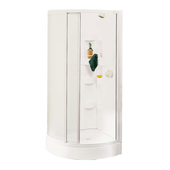
Tabla de contenido
Publicidad
Enlaces rápidos
100575 • 100584 • 100588 • 101107 • 101109 • 101111
read all instructions carefully before proceeding.
Lire toutes les instructions attentivement avant de commencer
l'installation.
Leer detenidamente todas las instrucciones antes de comenzar
la instalación.
important
• record the serial number
important
• noter le numéro de série
importante
• registre el número de serie
instaLLatiOn instructiOns
GuiDE D'instaLLatiOn
Guía para instaLación
MODEL • MODÈLE • MODELO
K3131-B • K3434-B • K3636-B
Save thiS guide for future reference.
conServer pour un uSage ultérieur.
conServe eSte manual como referencia.
Serial number • Numéro de série • Número de Serie
Publicidad
Tabla de contenido

Resumen de contenidos para MAAX 100575
- Página 1 GuiDE D’instaLLatiOn Guía para instaLación MODEL • MODÈLE • MODELO 100575 • 100584 • 100588 • 101107 • 101109 • 101111 K3131-B • K3434-B • K3636-B read all instructions carefully before proceeding. Save thiS guide for future reference.
- Página 3 PART No / No DE PIÈCE / No DE PARTE DESCRIPTION Ó I K3131-B K3434-B K3636-B QTÉ CANT 100575 / 101107 100584 / 101109 100588 / 101111 #10-32 X 5/8" SCREW (1,6 CM) VIS #10-32 X 5/8" (1,6 CM) TORNILLO #10-32 X 5/8" (1,6 CM) 10002814 10002814 10002814 WASHER 1/4"...
- Página 4 PART No / No DE PIÈCE / No DE PARTE DESCRIPTION Ó I QTÉ K3131-B K3434-B K3636-B CANT 100575 / 101107 100584 / 101109 100588 / 101111 #10-32 X 5/8" SCREW (1,6 CM) VIS #10-32 X 5/8" (1,6 CM) TORNILLO #10-32 X 5/8" (1,6 CM) 10002814 10002814 10002814 WASHER 1/4"...
-
Página 5: Lire Les Instructions Attentivement Avant De Procéder
Escuadra Taladro eléctrico 2 juntas de sujeción K3131-B / 100575 / 101107 and K3434-B / 100584 / 101109: Brocas de 3/32" y 7/32" 2 wooden pieces 1x3 x 8’ and 2 wooden pieces 2x3 x 8’ K3636-B / 100588 / 101111: K3131-B / 100575 / 101107 y K3434-B / 100584 / 101109: 4 wooden pieces 2x3 x 8’... - Página 6 2.1.1 Etapa 2 - EnsaMbLaJE DE Las barras DE rEtEnción fiG. 2.1 K3131-b / 100575 / 101107 a) Perfore agujeros con broca de 7/32" pul alineándolos con las molduras sobre las repisas. c) Ensamble las barras de retención (12) a las repisas con los tornillos autotrabadores #8 x ½"...
- Página 7 stEp 3 - WaLL assEMbLy a) Align walls on flat surface (Fig. 3). b) Using the wall with the pre-drilled holes as a guide, mark the holes to drill on the other wall. c) Drill the holes with a 7/32" bit. d) Apply silicone inside each wall slots (fig.
-
Página 8: Fig. 5.2
Fixez les pièces de renfort (2x3 x 17 1/2") tel qu’ilustré. fiG. 5.1 d) Déterminez l’emplacement de votre robinetterie. Note: les zones K3131-b / 100575 / 101107 ombragées correspondent à la position recommandée pour la robinetterie. K3434-B 33 3/8 44 1/2 36 1/2 22 1/4 8 1/4 Nous recommandons de fixer le pommeau de douche ou le support à... -
Página 9: Fig. 6.1
stEp 6- instaLLinG tHE sHOWEr in its LOcatiOn a) Complete drain assembly (refer to step 2, ASSEMBLY AND INSTALLATION of the instructions enclosed in the drain packaging) b) Slide the shower into its location. THE SHOWER BASE MUST BE UNI- FORMLY LEVELED AND RESTING OVER ITS ENTIRE SURFACE. -
Página 10: Etapa 9 - Inserción Del Marco Fijo
stEp 8 - assEMbLy Of fiXED fraME please note: the top rail (a) is different from the bottom rail (b), therefore, they cannot be inverted. Fig. 8.1. a) First of all, determine the opening direction of the door. To ensure that the shower is watertight, the fixed panel (D) must face the showerhead. - Página 11 " stEp 10 - assEMbLy Of sLiDinG panEL (f) a) Slide the decorative handle caps (N) on the worked part of handle at the exterior sliding panel (F) (Fig. 10.1). " b) Insert the splash guard ribbon(L) in the slot at the bottom of the sliding panel (F) (Fig. 10.2). Use a lubricant if necessary.
- Página 12 stEp 12 - sEaLinG a) Apply silicone around the outside perimeter of the bottom rail (B) (Fig. 12) and the wall jamb (C) (Fig. 12.1). Do not apply silicone on the inside of the shower, between the bottom rail and the shower base, or water will be trapped under the rail.
-
Página 13: Mantenimiento
MAAX can puisse exécuter la garantie spécifiée aux présentes. en el manual de instalación, con el fin de que MAAX execute the warranty specified herein. If such Si un tel accès n’existe pas, tous les coûts inhérents pueda cumplir con la garantía que se indica en este... -
Página 14: O De Adaptabilidad Para Un Uso
MAAX is not responsible for loss of use or profit del contratista o del constructor en un comercio d’un détaillant autorisé. MAAX n’est pas responsable under any circumstances. -
Página 15: Warranty & Service
(2) the user has informed an a informé un agent autorisé de MAAX ou un (2) el usuario ha informado a un agente autorizado authorized MAAX Agent or Warranty Service représentant du service de la garantie de la nature... - Página 16 / service technique / servicio técnico t. 1 877 361-2044 f. 1 888 361-2045 10011648 © 2008 MaaX bath inc. printED in canaDa / iMpriMé au canaDa / iMprEsO En canaDa 2012-02-02...


