Publicidad
Tabla de contenido
This manual, accompanied by sales receipt, should be saved and kept on hand as a convenient reference, as it
WARNING!
READ AND UNDERSTAND
OPERATOR'S MANUAL
BEFORE USING THIS UNIT.
FAILURE TO FOLLOW
OPERATING
INSTRUCTIONS COULD
RESULT IN INJURY OR
DAMAGE TO PROPERTY.
Write Model Number From
Box Here:
© COPYRIGHT 2008 by SPALDING
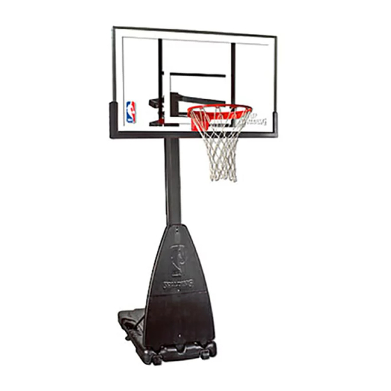
Portable System
Owners Manual
Customer Service Center
• N53 W24700 South Corporate Circle • Sussex, WI 53089 • U.S.A.
Adult Assembly Required.
contains important information about your model.
• 2 Capable Adults
• Tape Measure
• Wood Board (scrap)
• Sawhorse or Support
Table
• Hammer or Mallet
• Step Ladder 8 ft. (2.4m)
• Safety Glasses
Toll-Free Customer Service Number for U.S: 1-800-558-5234,
For Canada: 1-800-284-8339,
For Europe: 00 800 555 85234 (Sweden: 009 555 85234),
For Australia: 1800 632 792
Internet Address: www.spalding.com
REQUIRED TOOLS AND MATERIALS:
• (2 each) Wrenches
5/16"
1/2"
AND/OR
(2) Socket Wrenches and Sockets
5/16"
1/2"
• Extension
• Phillips-Head Screwdriver
• Portable Drill with
Torque Adjustment
1
• Garden Hose or Sand
9/16"
3/4"
9/16"
3/4"
• Optional: Large & Small
Adjustable Wrenches
12/07
ID# M680964
Publicidad
Tabla de contenido

Manuales relacionados para SPALDING NBA Platinum Helix Lift Portable


Resumen de contenidos para SPALDING NBA Platinum Helix Lift Portable
- Página 1 Torque Adjustment • Safety Glasses Toll-Free Customer Service Number for U.S: 1-800-558-5234, For Canada: 1-800-284-8339, For Europe: 00 800 555 85234 (Sweden: 009 555 85234), For Australia: 1800 632 792 Internet Address: www.spalding.com © COPYRIGHT 2008 by SPALDING 12/07 ID# M680964...
- Página 2 Numéro vert du Service clientèle - États-Unis : 1-800-558-5234, Canada : 1-800-284-8339, Europe : 00 800 555 85234 (Suède : 009 555 85234), Australie : 1-800-632 792 Adresse Internet: www.spalding.com Gebührenfreie Telefonnummer für die USA: 1-800-558-5234, für Kanada: 1-800-284-8339, für Europa: 00 800 555 85234 (Schweden: 009 555 85234), für Australien: 1-800-632 792 Internet-Adresse: www.spalding.com...
-
Página 3: Height Adjustment
OUTILS ET MATÉRIEL REQUIS BENÖTIGTE WERKZEUGE UND MATERIALIEN HERRAMIENTAS Y MATERIALES REQUERIDOS • Tuyau d’arrosage ou sable • Deux (2) adultes capables • (2) Clés (216 kg) (475 lb.) • Zwei (2) zur Ausführung dieser • (je 2) Schraubenschlüssel • Gartenschlauch oder Sand Arbeit fähige Erwachsene •... - Página 4 BEFORE YOU START AVANT DE COMMENCER! VORBEREITENDE MASSNAHMEN ¡ANTES DE COMENZAR! To ensure optimal playability of backboard system, a close tolerance fit between the elevator components and hardware is required. Test-fit large bolts into large holes of elevator tubes, backboard brackets, and triangle plates.
- Página 5 12/07 ID# M680964...
- Página 6 ID# M680964 12/07...
- Página 7 KÖNNEN ZU DEREN PLÖTZLICHEM BRUCH FÜHREN. WENN DIE KORBWAND VOR ODER NACH DEM ZUSAMMENBAU IN JEGLICHER WEISE BESCHÄDIGT WIRD, RUFEN SIE DIE FOLGENDE GEBÜHRENFREIE TELEFONNUMMER AN: Innerhalb der USA: 1-800-558-5234; innerhalb KANADAS: 1-800-284-8339; http://www.spalding.com ¡ADVERTENCIA! SI SU SISTEMA ESTÁ EQUIPADO CON UN RESPALDO DE ACRÍLICO, EXAMINE EL RESPALDO PARA VERIFICAR QUE NO HAYA SUFRIDO DAÑOS DURANTE EL TRANSPORTE.
- Página 8 NOTICE TO ASSEMBLERS Adult Assembly Required. Dispose of ALL packaging materials promptly. As with all products, periodically inspect for loose small parts. Assembled unit MUST be filled with sand or water at ALL times. ALL basketball systems, including those used for DISPLAYS, MUST be assembled and installed according to instructions.
- Página 9 Get to know the basic parts of your basketball system... Apprenez à connaître les composants de base de votre système de basket-ball... Machen Sie sich mit den wichtigsten Teilen Ihres Basketballsystems vertraut… Conozca las piezas básicas de su sistema de baloncesto… BACK VIEW FRONT VIEW VUE DE FACE...
-
Página 10: Parts List
PARTS LIST - See Hardware Identifier Item Qty. Part No. Description Item Qty. Part No. Description 600053 Tank 568090 Label, Height Adjustment and Moving 926410 Strut, Pole to Base FR568090 Label, French 80034403 Screw Jack Assembly 908355 Cover Plate, Rim 1 FR908559 Top Pole Section 908559 Support Arm, Upper... -
Página 11: Liste Des Pièces
LISTE DES PIÈCES - Voir légende Article Qté No. de réf. Description Article Qté No. de réf. Description 600053 Socle 908561 Bras de support, Partie inférieure 906410 Contrefiche, poteau/socle 568090 Étiquette, réglage de hauteur et déplacement FR568090 Étiquette, réglage de hauteur et 1 80034403 Cric à... - Página 12 TEILELISTE - Siehe Teileschlüssel Nr. Anz. Teilenummer Beschreibung Nr. Anz. Teilenummer Beschreibung 600053 Sockel 206340 Sechskant-Gegenmutter, 1/2-13 906410 Strebe, Stange zu Sockel 908561 Unterer Haltearm 80034403 Schraubenheber-Baugruppe 568090 Höheneinstell- und Transportaufkleber FR568090 Höheneinstell- und Transportaufkleber FR908559 Oberes Stangenteil 908355 Abdeckung, Korbrand FR908558 Mittleres Stangenteil 908559...
-
Página 13: Lista De Piezas
LISTA DE PIEZAS - Vea el identificador de herraje Artículo Cant. Pieza N.º Descripción Artículo Cant. Pieza N.º Descripción 600053 Base 201651 Espaciador, plástico, .530 D.I. x .25 de largo 906410 Puntal, poste a base 206340 Contratuerca, hexagonal, 1/2-13 1 80034403 Conjunto del gato de rosca 908561 Brazo de soporte inferior 1 FR908559 Sección superior del poste 568090 Etiqueta, ajuste de la altura y de... - Página 14 HARDWARE IDENTIFIER (BOLTS AND SCREWS) IDENTIFICATION DES PIÈCES (BOULONS ET VIS) BEFESTIGUNGSTEILESCHLÜSSEL (BOLZEN UND SCHRAUBEN) IDENTIFICADOR DE HERRAJE (PERNOS Y TORNILLOS) #29 (3) #12 (1) #39 (2) #26 (4) #20 (1) #18 (6) #16 (2) #23 (4) #27 (3) #25 (2) #48 (1) HARDWARE IDENTIFIER (PLASTIC SPACERS CAPS AND CLIPS) IDENTIFICATION DES PIÈCES (ENTRETOISES, CAPUCHONS ET PINCES EN PLASTIQUE)
- Página 15 HARDWARE IDENTIFIER (NUTS AND WASHERS) IDENTIFICATION DES PIÈCES (ÉCROUS ET RONDELLES) BEFESTIGUNGSTEILESCHLÜSSEL (MUTTERN UND UNTERLEGSCHEIBEN) IDENTIFICADOR DE HERRAJE (TUERCAS Y ARANDELAS) #10 (2) #14 (11) #31 (7) #51 (1) #52 (1) #24 (12) HARDWARE IDENTIFIER (OTHER) IDENTIFICATION DES PIÈCES (AUTRES) BEFESTIGUNGSTEILESCHLÜSSEL (SONSTIGE) IDENTIFICADOR DE HERRAJE (OTROS) #47 (1)
- Página 16 SECTION A: ASSEMBLE THE BASE SECTION A: MONTAGE DU SOCLE BAUABSCHNITT A: ZUSAMMENBAU DES SOCKELS SECCIÓN A: MONTAJE DE LA BASE This is what your system will look like when you’ve finished this section. Voici à quoi ressemblera votre système lorsque vous en aurez fini avec cette section.
- Página 17 Complete wheel assembly as shown in Figure A. Secure wheel bracket (7) and wheel assembly (Fig. A.) to the tank (1) with bolts (18) and washers (24). Repeat procedure for opposite wheel. Effectuez le montage des roues, comme indiqué à la figure A. Fixez le support des roues (7) et les roues (Fig.
- Página 18 Correctly identify each pole section. Poles have an identification sticker that will be used as a reference point in the next step. Identifiez correctement chaque section de poteau. Les poteaux ont une étiquette d'identification qui servira de point de repère à l'étape suivante. Jedes Stangenteil richtig identifizieren.
- Página 19 While maintaining alignment, bounce middle pole section (5) into top section (4) using a wood scrap as shown until the top pole no longer moves toward the pole identification sticker on the middle pole. Tout en maintenant l'alignement, entrechoquez les sections de poteau supérieure (4) et centrale (5) en utilisant une chute de bois, comme illustré, jusqu'à...
- Página 20 Bounce top and middle pole assembly (4 and 5) onto bottom pole section (6) using a wood scrap as shown. Bounce until the top and middle pole assembly no longer moves toward the pole identification mark on the bottom pole. Entrechoquez l'ensemble sections supérieure (4) et centrale (5) avec la section inférieure (6) à...
- Página 21 Attach pole assembly to base (1) as shown. Secure pole assembly to tank using bolts (25) and pole mounting bracket (19) as shown. Attachez le poteau au socle (1), comme illustré. Fixez le poteau au réservoir à l'aide des boulons (25) et du support de poteau (19), comme illustré.
- Página 22 Secure front tank struts (45) to tank (1) and wheel assemblies as shown. Fixez les entretoises (45) de réservoire avant sur le réservoir (1) et le montage des roues comme sur l’illustration. Befestigen Sie die Tankfrontverstrebungen (45) am Tank (1) und der Drehmontage, wie dargestellt. Asegurar los puntales frontales del tanque(45) al tanque y el conjunto de las ruedas como se muestra IMPORTANT!
- Página 23 IMPORTANT! Rotate non-secured ends of tank struts (2) outward to mounting holes in tank as IMPORTANT! shown. Position base frame under tank. Secure tank struts (2) and base frame to tank as shown. Repeat for opposite side. WICHTIG! ¡IMPORTANTE! Tournez les extrémités non fixées des contrefiches (2) vers l’extérieur afin de les Do not tighten completely.
- Página 24 Install pole mount bracket (15) and reinforcement bracket (42) with carriage bolts (16) as shown. Tighten flange nuts (14) completely. Installez le support du poteau (15) et le support de renforcement (42) à l'aide des boulons ordinaires (16), comme illustré. Serrez à fond les écrous à bride (14). Die Stangenmontagehalterung (15) und Verstärkungshalterung (42) wie gezeigt mit Schlossschrauben (16) befestigen.
- Página 25 Securely rest the assembly on sawhorse. Identify elevator tubes (32 and 35). Posez l'ensemble sur un banc de sciage. Identifiez les tubes du système élévateur (32 et 35). Den Aufbau sicher auf dem Sägebock ablegen. Für den nächsten Arbeitsschritt werden die Verlängerungsrohre (32 und 35) benötigt.
- Página 26 While the system is securely resting on the sawhorse. Install elevator tubes (32 and 35) to top pole section (4) as shown. Install pole cap (38) at this time. Pendant que le système repose bien calé sur le banc de sciage : Installez les tubes du système élévateur (32 et 35) sur la section de poteau supérieure (4), comme illustré.
- Página 27 SECTION B: ATTACH THE BACKBOARD SECTION B: ATTACHEZ LE PANNEAU BAUABSCHNITT B: ANBRINGEN DER KORBWAND SECCIÓN B: CONECTE EL RESPALDO This is what your system will look like when you’ve finished this section. Voici à quoi ressemblera votre système lorsque vous en aurez fini avec cette section.
- Página 28 While still supported on sawhorse. Attach elevator tubes (32, 35) to backboard using spacers (30), bolts (23), and nuts (31) as shown. Toujours sur le banc de sciage: Attachez le tubes du système élévateur (32, 35) au panneau à l’aide des entretoises (30), des boulons (23) et des écrous (31), comme illustré.
- Página 29 Insert T-bolt (48) into Slam Jam bracket (47) then, attach that assembly to board using bolts (26) and nuts (14). IMPORTANT! / IMPORTANT! Insérez le boulon en T (48) dans le support WICHTIG! / ¡IMPORTANTE! de Slam Jam (47), puis attachez l'ensemble Carefully cut and peel protective film au panneau à...
- Página 30 NOTE: REMARQUE: HINWEIS: NOTA: ORIENTATION OF BRACKET ORIENTATION DU SUPPORT AUSRICHTUNG DER HALTERUNG ORIENTACIÓN DEL SOPORTE ID# M680964 12/07...
- Página 31 Install Slam Jam Rim to Backboard A. Fit rim (46) securely into bracket (47) as shown. Allow T-bolt (48) to slip through center hole in rim (46). B. Install reinforcement bracket (49) onto T-bolt (48) as shown. C. Install spring (50) onto T-bolt (48) as shown. D.
- Página 32 Place cover (17) onto screw-jack assembly (3). Install cap (11). Placez le couvercle (17) sur le cric à vis (3). Installez le capuchon du poteau (11). Die Abdeckung (17) auf der Schraubenheber-Baugruppe (3) anbringen. Die Kappe (11) aufsetzen. Coloque la cubierta (17) en el conjunto del gato de rosca (3).
- Página 33 Secure the handle assembly to pole bracket (15) using bolt (20) and nut (10) as shown. Fixez l'ensemble de la poignée au support de poteau (15) à l'aide du boulon (20) et de l'écrou (10), comme illustré. Die Griffbaugruppe wie gezeigt mit Schraube (20) und Mutter (10) an der Stangenhalterung (15) befestigen. Asegure el conjunto de la manija en el soporte del poste (15) usando un perno (20) y una tuerca (10) como se muestra.
- Página 34 Roll completed assembly to desired position. Fill tank with water (approx. 40 gallons (151 Liters)) or sand (approx. 475 lbs. (216 kg)) and rotate the cap (41) into base (1). Faites rouler l'ensemble jusqu'à la position désirée. Remplissez le réservoir d'eau (151 litres environ) ou de sable (216 kg environ) et installez le bouchon (41).
- Página 35 Attach stadium pad (28) to pole using bolts (27), nuts (14), and vinyl covers (44). Fixez le tapis de stade (28) au poteau avec les boulons (27), les écroux (14) et les couverts de vinyl(44). Befestigen Sie das Stadiumpad (29) mit den Bolzen (27), Muttern (14) und Vinylabdeckungen (44) am Pfosten.
- Página 36 Apply Height Adjustment and Moving Label (33) CAUTION! / ATTENTION! to front of pole, where it is clearly visible. VORSICHT! / ¡PRECAUCIÓN! Apposez l'étiquette de réglage de la hauteur et DO NOT OVER-CRANK HANDLE BEYOND THE de déplacement (33) sur l'avant du poteau, à un MANUFACTURED HEIGHT-INDICATOR RANGE OF endroit bien visible.
- Página 37 COVER / PROTECTION / ABDECKUNG / CUBIERTA NOTE: / REMARQUE: HINWEIS: / NOTA: Cover plate (28) will fit INSIDE back bracket. La plaque de protection (28) logera à l'INTÉRIEUR du support arrière. Die Abdeckplatte (28) passt IN die hintere Halterung. La placa de cobertura (28) cabrá...
- Página 38 PARTS LIST (See Hardware Identifier) LISTE DES PIÈCES (Voir la légende des illustrations) Item Qty. Part No. Description Légende Quantité No de réf. Description 600063 Board Pad, Left Section 600063 Guêtre du panneau, partie gauche 600064 Board Pad, Right Section 600064 Guêtre du panneau, partie droite 600082 Board Pad, Middle 600082 Rembourrage du panneau, section...
- Página 39 BOARD PAD - INSTALLATION The enclosed Molded Edge Guards interlock together to form bottom and side protection for one backboard with an overall width of 44 - 60". Les protecteurs sur chant profilé disponibles s’emboîtent pour une protection de la partie inférieure et latérale d’un panneau avec une largeur totale de 111.8 - 152.4 cm.
- Página 40 Using a 5/16 socket wrench or portable drill with a 5/16 socket attachment with the torque adjustment at the lowest setting, fasten the edge guards in place with the provided self-drilling, self-tapping screws (3). A l’aide d’une clé à douille 8mm ou d’une perceuse portative munie d’une douille de 8mm, ajustez le couple de serrage en le plaçant sur le niveau le plus bas.
- Página 41 Using a portable drill (with adjustable torque) and a 5/16 socket and extension drill through the backboard frame and secure the pads in place with self-tapping screws provided (3). USE CAUTION WHEN DRILLING BECAUSE THE HOLE WILL BE CREATED NEAR THE EDGE.
- Página 42 APPLY HEIGHT INDICATOR DECALS FIXEZ LES ETIQUETTES AUTOCOLLANTES DU REPERE DE HAUTEUR HÖHENANZEIGER-AUFKLEBER ANBRINGEN APLIQUE LAS CALCOMANÍAS DEL INDICADOR DE ALTURA Apply Height Indicator Labels (53) to screw jack using ruler on page 43 as a placement guide. Fixez les etiquettes autocollantes (53) à la vis de calage en vous servant de la règle à la page 43 comme guide. Bringen Sie die Höhenanzeiger-Aufkleber (53) unter Verwendung des Lineals auf Seite 43 als Platzierungsschablone an der Hubspindel an.
- Página 43 P/N 204872 Line up top edge with bottom of screw jack P/N 204872 FIG. A. sleeve (FIG. A.) ABB. A. Alignez le bord supérieur avec le bas du manchon de la vis de calage. (Fig A). Oberkante mit dem unteren Rand der Hubspindelhülse ausrichten (ABB.