Tabla de contenido
Publicidad
Idiomas disponibles
Idiomas disponibles
Enlaces rápidos
Publicidad
Capítulos
Tabla de contenido

Manuales relacionados para Amprobe GP-2A


Resumen de contenidos para Amprobe GP-2A
- Página 1 GP-2A Earth Ground Tester Users Manual • Manual de uso...
- Página 3 GP-2A Earth Ground Tester Users Manual GP-2A_Rev002 © 2012 Amprobe Test Tools. All rights reserved.
- Página 4 Limited Warranty and Limitation of Liability Your Amprobe product will be free from defects in material and workmanship for 1 year from the date of purchase. This warranty does not cover fuses, disposable batteries or damage from accident, neglect, misuse, alteration, contamination, or abnormal conditions of operation or handling. Amprobe’s warranty obligation is limited, at Amprobe’s option, to refund of the purchase price, free of charge repair, or replacement of a defective product . Resellers are not authorized to extend any other warranty on Amprobe’s behalf. To obtain service during the warranty period, return the product with proof of purchase to an authorized Amprobe Test Tools Service Center or to an Amprobe dealer or distributor. See Repair Section for details. This warranty is your only remedy . All other warranties - whether express, implied or statutory - including implied warranties of fitness for a particular purpose or merchantability, are hereby excluded. Neither Amprobe nor its parent company or affiliates shall be liable for any special, indirect, incidental or consequential damages or losses, arising from any cause or theory. Since some states or countries do not allow the exclusion or limitation of an implied warranty or of incidental or consequential damages, this limitation of liability may not apply to you. Repair All test tools returned for warranty or non-warranty repair or for calibration should be accompanied by the following: your name, company’s name, address, telephone number, and proof of purchase. Additionally, please include a brief description of the problem or the service requested and include the test leads with the meter. Non-warranty repair or replacement charges should be remitted in the form of a check, a money order, credit card with expiration date, or a purchase order made payable to Amprobe® Test Tools. In-Warranty Repairs and Replacement – All Countries Please read the warranty statement and check your battery before requesting repair. During the warranty period any defective test tool can be returned to your Amprobe® Test Tools distributor for an exchange for the same or like product. Please check the “Where to Buy” section on www. amprobe.com for a list of distributors near you. Additionally, in the United States and Canada In- Warranty repair and replacement units can also be sent to a Amprobe® Test Tools Service Center (see below for address).
-
Página 5: Tabla De Contenido
GP-2A Earth Ground Tester CoNTENTS 1. SAFETY PRECAUTIoNS AND PRoCEDURES ..................2 1.1 Preliminary instructions ......................2 1.2 During use ..........................3 1.3After use ............................3 1.4 Definition of measurement category (Overvoltage) ............... 3 2. GENERAL DESCRIPTIoN ........................4 2.1 Instrument description....................... 4 3. PREPARING THE INSTRUMENT ......................4 3.1 Initial check..........................4 3.2 Power supply ..........................4 3.3 Calibration ..........................4 3.4 Storage............................4 4. -
Página 6: Safety Precautions And Procedures
1. SAFETY PRECAUTIoNS AND PRoCEDURES The instrument was designed in compliance with standards EN61557 and EN61010-1 relative to electronic equipment. �CAUTION For your own safety and to avoid damaging the instrument you are recommended to follow the procedures described in this manual and read carefully all instructions preceded by this symbol� Before and during measurements keep to the following instructions: • Do not take measurements in wet places as well as in the presence of explosive gas and combustibles or in dusty places. • Even though you are not taking any measurement avoid any contact with the circuit under test, with exposed metal parts, unused measuring terminals, circuits etc. • Do not take any measurement any measurement whenever anomalous conditions occur such as deformations, breaks, leakages, blind display etc. • Pay utmost attention when taking measurements of voltage higher than 25V in special places (building yards, swimming pools, etc.) and higher than 50V in ordinary places due to the risk of electric shock. The following symbols are used in this manual as well as on the instrument: CAUTIoN: Please read carefully this manual in order to understand the nature of the potential danger and the actions to undertake �... -
Página 7: During Use
1.2 During Use You are recommended to read carefully the following instructions: �CAUTION Failure to comply with warnings and instructions may damage the instrument and/or its components as well as injure the operator If the low battery symbol is displayed during use interrupt testing and replace batteries following the procedure described in paragraph 8.2 • Before selecting a new function disconnect the test leads from the circuit under test. • When the instrument is connected to the circuit under test never touch any unused terminal. • Do not measure resistance in the presence of external voltages; although the instrument is protected, an excessive voltage may cause malfunction. • Avoid submitting the instrument to voltage while measuring (i.e. a test lead slipping off the measuring point accidentally touching an energized point).Unpacking And Inspection 1.3 After Use • Turn off the instrument pressing ON/OFF key after using it. • If you expect not to use the instrument for a long time remove the batteries. 1.4 Definition of Measurement Category (overvoltage) The standards EN61010-1: Safety requirements for electrical equipment for measurement, control and laboratory use, Part 1: General requirements, define what a measurement category, usually called over voltage category, means. Under paragraph 6.7.4: Measuring circuits, it quotes: Circuits are divided into the following measurement categories: • Measurement category IV is for measurements performed at the source of a low-voltage installation. • Examples are electricity meters and measurements on primary excess current protection devices as well as ripple control units. Measurement category III is for measurements performed in the building installations. • Examples are measurements on distribution boards, circuit breakers, wiring, including cables, bus-bars, junction boxes, switches, socket-outlets in the fixed installations, and equipment for industrial use as well as some other equipment, for example, stationary motors with permanent connection to fixed installations. Measurement category II is for measurements performed on circuits directly connected to the low voltage installations. • Examples are measurements on household appliances, portable tools and similar equipment. -
Página 8: General Description
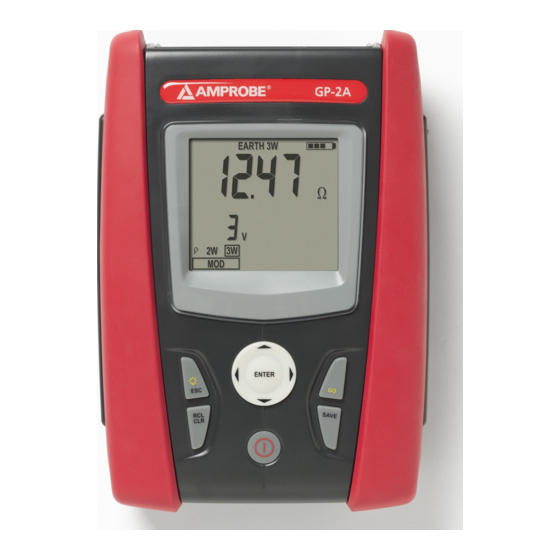
2.1 Instrument Description • EARTH 2W: two-wire earth resistance measurement. • EARTH 3W: three-wire earth resistance measurement. • r : four-wire ground resistivity measurement. 3. PREPARING THE INSTRUMENT 3.1 Initial Check This instrument was checked both mechanically and electrically prior to shipment. All possible cares and precautions were taken to let you receive the instrument under perfect conditions. Notwithstanding we suggest you to check it rapidly to check any damage which may have occurred during transport. Should it be the case please contact immediately the forwarder or your dealer. Your shipping carton should include: 1 GP-2A 4 Ground stakes 1 Test lead set (banana – banana) 1 Alligator clip set 1 Optical USB cable 1 USB driver CD 1 Carrying case 1 User’s manual If any of the items are damaged or missing, return the complete package to the place of purchase for an exchange. 3.2 Power Supply The instrument is powered by batteries (refer to paragraph 9.2.2 for further details on model, number and battery life). The battery charge is displayed on the right top side. The symbol... -
Página 9: Working Instructions
4. WoRKING INSTRUCTIoNS 4.1 Instrument Description Inputs ENTER / Arrow keys ENTER key to select measuring mode Arrow keys to move the cursor selecting the required parameters Back light key / ESC Back light key to turn on the display backlight for 30 seconds ESC key to quit without selecting any mode RCL / CLR key RCL key to recall data stored in the instrument’s memory CLR key to cancel the selected measurements from the instrument’s memory Display Go key to start a measurement SAVE key to store measurements oN/oFF key to turn on/off the instrument... -
Página 10: Measuring Accessories Description
4.2 Measuring Accessories Description Barrier Hand-Held Area Fig. 1 4.2.1 Switching on When switching on the instrument a brief tone is audible along with display of all segments for about one second. Subsequently the last firmware version as well as the last selected measuring mode are displayed before switching off. 4.2.2 Auto power off The instrument automatically turns off 3 minutes after the last key pressing. To resume operation turn on the instrument pressing the on/off key. -
Página 11: Earth 3W - Three Wire Earth Resistance Measurement
4.3 EARTH 3W – Three Wire Earth Resistance Measurement The measurement is carried out in compliance with standards IEC 781, VDE 0413, EN61557-5. �CAUTION • The instrument can be used for voltage and current measurements on installations with over voltage category CAT III 240V to earth and maximum voltage of 415V between inputs. Do not connect the instrument to installations whose voltages exceed the limits indicated in this manual. Exceeding such limits may cause electric shock to the user and damage the instrument • Always connect the cables to the instrument and to the alligator clips when the latter are not connected to the plant under test • Always respect the Hand-held area of probe (see 4.2) • If the length of the supplied cables isn’t suitable for the plant under test (see Par. 11), You can create your own extensions following indications in Par. 11.2.1 Fig. 2: Three-wire earth resistance measurement Turn on the instrument pressing the ON/OFF key Pressing right/left arrow keys , select MOD, then pressing up/down arrow keys , select 3W option A screen similar to the one below appears where the input interfering voltage value of the instrument is displayed (Input interfering voltage value) Connect the blue, red, green and black cables to the corresponding instrument’s input terminals H, S, ES, E then adding crocodiles if necessary Extend, if necessary, the blue and red measuring cables separately using cables with proper section. Adding any extension does not require calibration and does not affect the measured earth resistance value Drive the auxiliary rods into the ground keeping to the distance instructions provided by the standards (§ 11.2) Connect crocodiles to the auxiliary rods and to the installation under test (see Fig. 2) - Página 12 Press GO key, the instrument starts carrying out measurement While the instrument is measuring a screen similar to the one below appears where the instrument’s input interfering voltage value is displayed. When the message is displayed do not disconnect or touch the test leads (Input interfering voltage value) �CAUTION When starting measurement the input interfering voltage is measured at both the volt and ampere circuit. Should it range between 3 V and 9 V, the instrument carries out measurement and displays the symbol � indicating the uncertainty decline of the measurement (§ 9.1) 10. When the test is over, should the earth resistance value be lower than the full scale, the instrument emits a double tone indicating the positive outcome of the test and displays the resistance measurement as well as the interfering voltage value at the time of measuring (Earth resistance measurement) (Input interfering voltage value) �CAUTION The resistance measurement is effected with 4-wire volt ampere method without being affected by the resistance value of the cables. It is therefore not necessary to effect compensation of cable resistance or of any extension 11. When the test is over, should the earth resistance value be higher than the full scale, the instrument emits a long tone indicating the negative outcome of the test and displays the screen below (Earth resistance measurement higher than full scale) (Input interfering voltage value) 12. The measurements can be stored pressing the SAVE key twice (§ 5.1)
-
Página 13: Earth 2W - Two Wire Earth Resistance Measurement
4.4 EARTH 2W – Two Wire Earth Resistance Measurement �CAUTION • The instrument can be used for voltage and current measurements on installations with over voltage category equal to CAT III 240V to earth and maximum voltage of 415V between inputs. Do not connect the instrument to installations whose voltages exceed the limits indicated in this manual. Exceeding such limits may cause electric shock to the user and damage the instrument • Always connect the cables to the instrument and to the alligator clips when the latter are not connected to the plant under test • Always respect the Hand-held area of probe (see 4.2) • If the length of the supplied cables isn’t suitable for the plant under test (see Par. 11), You can create your own extensions following indications in Par. 11.2.1 Whenever it is not possible to drive rods into the ground to take a three-wire measurement (i.e. historical centres), it is possible to use the simplified two-wire method which gives an excess value for the sake of safety. To carry out the test a suitable auxiliary rod is necessary; an auxiliary rod is deemed as suitable when its earth resistance is negligible and independent of the earth installation under test. In Fig. 3 a lamp post is used as auxiliary rod, however any metal body driven into the ground can be used provided that the above mentioned requirements are met. �CAUTION The instrument displays the sum value of RA+RT as result (see Fig. 3 and Fig. 4). Therefore the measurement achieved is the closer to RA (prospective value) the more negligible is the value RT of the auxiliary rod with respect to RA itself. In addition the measurement will be increased “for safety sake” by RT, i.e. if RA+RT results to be coordinated with protective conductors, RA alone will be far more coordinated Fig. 3: Two-wire earth resistance measurement using an auxiliary rod In the TT systems (see Fig. 4) it is possible to perform a two-wire earth measurement using the NEUTRAL conductor provided by the national Energy Board taken directly from a socket or panel board as an auxiliary rod; if also the earth connection is available, the measurement can be taken on the socket directly, between NEUTRAL and EARTH. �CAUTION If you wish to effect the measurement using the neutral and earth conductors of an ordinary socket, you may accidentally connect to phase; in this case the detected voltage as well as the warning symbol for wrong entering will be displayed and no measurement will be effected even though the... - Página 14 Fig. 4: Two-wire earth resistance measurement from the panel board Turn on the instrument pressing the ON/OFF key Pressing right/left arrow keys , select MOD, then pressing up/down arrow keys , select 2W option A screen similar to the one below appears where the input interfering voltage value of the instrument is displayed (Input interfering voltage value) Connect the blue, red, green and black cables to the corresponding instrument’s input terminals H, S, ES, E then adding crocodiles if necessary Extend, if necessary, the blue and red measuring cables separately using cables with proper section. Adding any extension does not require calibration and does not affect the measured earth resistance value Connect crocodiles to the auxiliary rods and to the installation under test (see Fig. 3 and Fig. 4) Press GO key, the instrument starts carrying out measurement While the instrument is measuring a screen similar to the one below appears where the instrument’s input interfering voltage value is displayed. When the message is displayed do not disconnect or touch the test leads (Input interfering voltage value)
-
Página 15: R - Ground Resistivity Measurement
�CAUTION When starting measurement the input interfering voltage is measured at both the volt and ampere circuit. Should it range between 3 V and 9 V, the instrument carries out measurement and displays the symbol � indicating the uncertainty decline of the measurement (§ 9.1) When the test is over, should the earth resistance value be lower than the full scale, the instrument emits a double tone indicating the positive outcome of the test and displays the resistance measurement as well as the interfering voltage value at the time of measuring (Earth resistance measurement) (Input interfering voltage value) �CAUTION The resistance measurement is effected with 4-wire volt ampere method without being affected by the resistance value of the cables. It is therefore not necessary to effect compensation of cable resistance or of any extension 10. When the test is over, should the earth resistance value be higher than the full scale, the instrument emits a long tone indicating the negative outcome of the test and displays the screen below (Earth resistance measurement higher than full scale) (Input interfering voltage value) 11. The measurements can be stored pressing the SAVE key twice (§ 5.1) 4.5 r - Ground Resistivity Measurement The ground resistivity value is an essential parameter to calculate the resistance value of the earth rods to be used for the earth installation’s construction. The measurement is effected according to standards IEC 781, VDE 0413 EN61557-5. �CAUTION • The instrument can be used for voltage and current measurements on installations with over voltage category equal to CAT III 240V to earth and maximum voltage of 415V between inputs. Do not connect the instrument to installations whose voltages exceed the limits indicated in this manual. Exceeding such limits may cause electric shock to the user and damage the instrument • Always connect the cables to the instrument and to the alligator clips when the latter are not connected to the plant under test • Always respect the Hand-held area of probe (see 4.2) • If the length of the supplied cables isn’t suitable for the plant under test (see Par. 11), You can create your own extensions following indications in Par.11.2.1... - Página 16 Fig. 5: Ground resistivity measurement Turn on the instrument pressing the ON/OFF key Pressing right/left arrow keys , select MOD, then pressing up/down arrow keys , select option A screen similar to the one below appears where both the input interfering voltage of the instrument and the rods’ distance value are displayed (Value of input interfering voltage and rods’ distance set) Should you need to modify the rods’ distance press the arrow keys , and select DIST, then pressing the arrow keys , set the desired distance (ranging from 1 up to 10 metres, by steps of one or from 3 up to 30 feet by steps of three) (Value of rods’ distance set) To set the distance measuring unit press the arrow keys , and select UNIT,...
- Página 17 then pressing the arrow keys , set the desired measuring unit (m or ft) (Measuring unit selected) Connect the blue, red, green and black cables to the corresponding instrument’s input terminals H, S, ES, E then adding crocodiles if necessary Extend, if necessary, the blue and red measuring cables separately using cables with proper section. Adding any extension does not require calibration and does not affect the measured ground resistivity value Drive the auxiliary rods into the ground placing them on a line at a mutual distance equal to that selected on the instrument. Setting a distance other than the actual distance between the earth rods may affect the measurement (§11.3) Connect crocodiles to the auxiliary rods (see Fig. 5) 10. Press GO key, the instrument starts carrying out measurement 11. While the instrument is measuring a screen similar to the one below appears where the instrument’s input interfering voltage value and the distance set between auxiliary rods are displayed. When the messageis displayed do not disconnect or touch the test leads (Value of input interfering voltage and rods’ distance set) �CAUTION When starting measurement the input interfering voltage is measured at both the volt and ampere circuit. Should it range between 3 V and 9 V, the instrument carries out measurement and displays the symbol � indicating the uncertainty decline of the measurement (§ 9.1) 12. When the test is over, should the ground resistivity value be lower than the full scale, the instrument emits a double tone indicating the positive outcome of the test and displays the resistivity measurement as well as the interfering voltage value at the time of measuring (Measurement of ground resistivity) (Value of input interfering voltage and rods’ distance set)
-
Página 18: Anomalous Measuring Applications - All Modes
�CAUTION The resistivity measurement is effected with 4-wire volt ampere method without being affected by the resistance value of the cables. It is therefore not necessary to effect compensation of cable resistance or of any extension. 13. When the test is over, should the ground resistivity value be higher than the full scale, the instrument emits a long tone indicating the negative outcome of the test and displays the screen below (Measurement of ground resistivity higher than the full scale) (Value of input interfering voltage and rods’ distance set) �CAUTION The full scale is calculated as PMAX = 2 DIST R where DIST is the value set for the distance among the rods and R the maximum resistance value which can be measured by the instrument. The full scale of ground resistivity measurement depends on the setting of the distance among the rods 14. The measurements can be stored pressing the SAVE key twice (§ 5.1) 4.5.1 Anomalous measuring applications – all modes When starting a measurement the instrument checks the continuity of measuring cables. If the volt circuit (red cable S and green cable ES) is interrupted or its resistance value is too high, the instrument displays a screen similar to the one below. Check that terminals are properly connected and that the earth rod is connected to terminal S and not driven into a pebbly or scarcely conductive ground. In this latter case pour water around the rod to decrease its resistance value (§ 11.2). RP>top is displayed when: The S rod’s resistance RS > 50KΩ is summed up to the volt circuit The resistance of rod S exceeds the value 1200 + 100 RX [Ω] (where RX is the earth resistance value) (Volt circuit’s resistance too high) (Value of input interfering voltage) (Example for 3W mode) When starting a measurement the instrument checks the continuity of measuring cables. If the ampere circuit (blue cable H and black cable E) is interrupted or its resistance value is too high, the instrument displays a screen similar to the one below. Check that terminals are properly connected and that the earth rod is connected to terminal H and not driven into a pebbly or scarcely conductive ground. In this latter case pour water... - Página 19 The H rod’s resistance RH > 50KΩ is summed up to the ampere circuit The resistance of rod H exceeds the value 1200 + 100 RX [Ω] (where RX is the earth resistance value) (Ampere circuit’s resistance too high) (Value of input interfering voltage) (Example for 3W mode) When starting a measurement the instrument checks the continuity of measuring cables. If the volt circuit (red cable S and green cable ES) and the ampere circuit (blue cable H and black cable E) are both interrupted or their resistance values are too high, the instrument displays a screen similar to the one below. Check that the terminals are properly connected and that the earth rods connected to terminals S and H are not driven into a pebbly or scarcely conductive ground. In this latter case pour water around the rods to decrease their resistance value (§ 11.2). RP, RC>top is displayed when: the S rod’s resistance RS > 50KΩ is summed up to the volt circuit and the H rod’s resistance H RH > 50KΩ is summed up to the ampere circuit both the S rod’s resistance and the H rod’s resistance exceed the value 1200 + 100 RX [Ω] (where RX is the earth resistance value) (Both volt and ampere circuits’ resistance too high) (Value of input interfering voltage) (Example for 3W mode) When starting a measurement, if the red cable (connected to S terminal) and the green cable (connected to ES terminal) are reversed, the instrument does not effect the test, emits a long sound tone and displays the screen below (Red and green cables reversed) (Example under mode) When starting a measurement, if an interfering voltage higher than 9V is detected at the volt circuit’s input, the instrument does not effect the test, emits a long sound tone and displays the screen below...
- Página 20 (Too high input interfering voltage at volt circuit) (Input interfering voltage value) (Example under 2W mode) When starting a measurement, if an interfering voltage higher than 9V is detected at the ampere circuit’s input, the instrument does not effect the test, emits a long sound tone and displays the screen below (Example under 2W mode) When starting a measurement, if an interfering voltage higher than 9V is detected at both the ampere and volt circuits’ inputs, the instrument does not effect the test, emits a long sound tone and displays the screen below (Too high input interfering voltage at both ampere and volt circuits) (Input interfering voltage value) (Example under 2W mode) If battery voltage is too low the instrument displays the symbol of low battery as well as the message LOW BATT and no measurement is allowed. It is however possible to carry out settings, reading of stored data, etc (Too low power supply, low batteries) (Input interfering voltage value and distance set among rods) (Example under mode) The above said anomalous cases cannot be stored...
-
Página 21: Management Of Stored Data
5. MANAGEMENT oF SToRED DATA 5.1 How To Save A Measurement After taking a measurement press SAVE key, the instrument displays a screen similar to the one below (No. of memory location where the measurement has to be saved) (Last value set for parameters L and P) Should you need to modify the values of the parameters L and P press the arrow keys , and select L or P, then pressing the arrow keys , set the desired value (from 1 to 255). These values can enable you to trace back the place where the measurement was effected or Confirm measurement storing pressing SAVE key or ENTER key 5.2 How To Cancel one or Several Measurements Press RCL key, the instrument displays a screen similar to the one below (Number of the last memory location used) (Values of L and P parameters) Press the arrow keys , to select the memory location where cancellation of data is to be started , the displays a screen similar to the one below (Number of the memory location where cancellation is to be started) -
Página 22: How To Recall A Measurement
Press the CLR key, the instrument displays a screen similar to the one below Alternatively: Confirm cancellation of measurements pressing ENTER key, the instrument emits a double sound tone confirming cancellation of the selected measurements Press ESC key to go back to previous screen 5.3 How To Recall A Measurement Press the RCL key, the instrument displays a screen similar to the one below (Number of the last memory location) (Values of L and P parameters) 2. Press the arrow keys , to select the memory location whose content is to be displayed (Number of the memory location whose content is to be displayed) (Values of L and P parameters) -
Página 23: Instrument Reset And Default Parameters
Press the ENTER key to display the measurement stored inside the selected memory location, the instrument displays a screen similar to the one below (Measurement stored in the selected memory location) (Values of interfering voltage at measurement) Press the ESC key to go back to previous screen and press the ESC key again to exit the memory management 6. INSTRUMENT RESET AND DEFAULT PARAMETERS �CAUTION Before carrying out the instrument’s reset save all data relative to the measurements effected by downloading them to a pc. When the instrument is off press the RCL/CLR key Keeping down the RCL/CLR key, press the switch on key. The instrument emits a short sound tone showing all display segments for approx. 1 second. Then it emits a second short sound tone displaying the screen beside for approx. 3 seconds �CAUTION The HARD RESET procedure deletes all data previously stored and the parameter DST resumes its default value (1 m or 3 ft) 7. INSTRUMENT CoNNECTIoN To PC The instrument can be connected to a PC by means of the serial port or USB and opt insulated cable provided along with the software package. First it’s necessary to select the COM port used for the transmission and the correct baud rate (9600 bps). To set these parameters install the software and consult the help on line. The selected port shall be free of any other device or application such as mouse, modem, etc. �CAUTION Optical port emits Laser radiations , Don’t locate beam at eye level. Class 1M laser apparatus according to EN 60825-1... -
Página 24: Maintenance
To transfer stored data to PC keep to the following procedure: Turn on the instrument pressing the power key Connect the instrument to a PC by means of the opt insulated cable provided with the software package. Communication is enabled at any function except for measurements as well as when memory management is active (§ 5) Use the data management software to download the instrument’s stored data to a PC. During the data transfer the instrument displays a screen as beside, then after completing the data transfer goes back to the previously selected mode 8. MAINTENANCE 8.1 General This is a precision instrument. Strictly follow the instructions for use and storage reported in this manual to avoid any possible damage or danger during use. Do not use this tester under unfavorable conditions of high temperature or humidity. Do not expose to direct sunlight. Be sure to turn off the tester after use. If the instrument is not to be used for a long period you are recommended to remove batteries to avoid leakages of battery liquid which may damage its internal circuits. 8.2 Battery Replacement When the low battery indication is displayed the batteries are to be replaced. �CAUTION Only skilled technicians can open the instrument and replace batteries. Before removing batteries disconnect all cables from input terminals Turn off the instrument pressing the ON/OFF key for a while Disconnect the cables from the input terminals Remove the battery cover screws and detach the battery cover Replace batteries with new ones of the same type (§ 9.2.2) keeping to the right polarity signs Replace cover and screws Use the appropriate battery disposal methods for your area 8.3 Instrument Cleaning Use a soft dry cloth to clean the instrument. Do not use wet clothes, solvents, water etc. 8.4 End of Life Caution: this symbol indicates that equipment and its accessories shall be subject to a separate collection and correct disposal. -
Página 25: Technical Specifications
9. TECHNICAL SPECIFICATIoNS 9.1 Definitions The standard introduces the uncertainty inherent uncertainty IEC/EN61557-5 overall (operational). The intrinsic uncertainty is the uncertainty of the instrument when it is used in reference conditions. The operating error applies under the rated operating conditions given in IEC1557-1 and the following: • following: injection of series interference voltages across the terminals E (ES) and S with a RMS value of 3V and system frequencies of: o 0Hz (DC) o 16 + 2/3 Hz o 50Hz o 60Hz o 400Hz • resistance of the auxiliary earth electrode and of the probes: 0 to 100 x RA but ≤ 50 kΩ The maximum percentage operating error within the measurement range does not exceed ± 30 % with the measured value as fiducially value, as determined in accordance with the following TABLE: Intrinsic Reference conditions or Designation Requirements or test Type uncertainty or specified operating range code in accordance with the of test influence quantity relevant parts of IEC 61557 Intrinsic Reference conditions Part 5, 6.1 uncertainty Position Reference position ± 90° Part 1, 4.2 Supply voltage At the limits stated by the... -
Página 26: Technical Features
9.2 Technical Features 3- and 2-wire earth resistance measurement - EARTH 3W and EARTH 2W Range [Ω](**) Resolution [Ω] Operating uncertainty 0.01 ÷ 19.99 0.01 20.0 ÷ 199.9 200 ÷ 1999 ± (2.5% reading + 2 digits) 2.00 ÷ 19.99k 0.01k 20.0 ÷ 49.9k 0.1k Operating uncertainty (according to EN61557) Intrinsic Influence quantity Fiducial operating Read.o Uncertainty Value uncertainty B [Ω] [Ω] [Ω] [Ω] [Ω] [Ω] [Ω] [Ω] [Ω] 17.986 18.00 0.014 0.01 0.00 0.05 0.04... -
Página 27: Safety Standards
Interfering voltage measurement Range (**) Resolution [V] Uncertainty (*) Reading [V] Measure [V] 0 ÷ 460 7 ÷ 460 ± (2.0% read.+2digit) 9.2.1 Safety standards Instrument’s safety: IEC / EN61010-1, IEC / EN61557-1, IEC / EN61557-5 Technical literature: IEC / EN61187 Measuring accessories’ safety: IEC / EN61010-031 Insulation: Class 2, Double insulation Type of Protection: IP50 according IEC / EN60529 Pollution level: Over voltage category: CAT III 240V (to earth), maximum 415V between inputs Ambient conditions: maximum altitude: 2000m Installations characterized by Safety Voltage 25V 9.2.2 General features Mechanical features Dimensions: 235(L) x 165(W) x 75(H) mm Weight (including batteries): approx. 1000g Power supply Battery type: 6 batteries 1.5V AA R6 MN1500 or 6 Batteries 1.2V AA R6 Ni-MH 2100mA rechargeable batteries Low battery indication: low battery symbol... -
Página 28: Practical Reports For Electrical Tests
10. PRACTICAL REPoRTS FoR ELECTRICAL TESTS 10.1 Earth Resistance In TT Systems The test is aimed at checking that the RCD is coordinated with the earth resistance value. It is not possible to assume an earth resistance value as reference limit (for example 20 as per art. 326 of DPR 547/55) when controlling the test result, while it is necessary to check every time that the co-ordination complies with the requirements of the Standards. The parts to be checked are represented by the whole earth installation under working conditions. The check is to be effected without disconnecting the earth rods. The earth resistance value measured shall meet the following relation R < 50 / Ia where: = resistance of the earth installation whose value can be set with the following measurements: • Three-wire earth resistance with volt ampere method • Two-wire earth resistance with volt ampere method • Phase to earth fault loop impedance (*) • Two-wire earth resistance in the socket with volt ampere method (**) • Earth resistance obtained by the measurement of contact voltage Ut (**) • Earth resistance obtained by the tripping time test of the RCDs (A, AC),RCD S (A, AC) (**) Ia = tripping current in 5s of the automatic RCD; rated tripping current of the RCD (in case of RCD S 2 I∆n) in ampere 50 = safety limit voltage (reduced down to 25V in special environments) (*) If the installation is protected by an RCD the measurement shall be effected upstream or downstream the RCD short-circuiting it to avoid its tripping (**) This method, even though not presently provided for by standards, provide values, which compared with numberless reference 3-wire tests resulted to be reliable for earth resistance Example Let’s assume an installation protected by an RCD Ia = 30 mA. The earth resistance is measured using one of the methods quoted above. To evaluate whether the installation resistance is complying with the standards in force multiply the result by 0.03A (30 mA). If the result is lower than 50V (or 25V for special environments) the installation can be considered as coordinated as it meets the above said relation. -
Página 29: Method For Small-Sized Earth Rods
10.2.2 Method for small-sized earth rods Let a current stream between the earth rod under test and an auxiliary probe placed at a distance equal to fivefold the diagonal of the area limiting the earth installation itself. Place the voltage probe at approximately half way between the earth rod and the current probe, finally measure voltage between both of them. Fig. 6: Earth resistance measurement – small-sized earth rods 10.2.3 Method for large-sized earth rods This procedure is based on the volt ampere metric method as well, however it is mainly used whenever it is difficult to place an auxiliary current rod at a distance equal to fivefold the diagonal of the area limiting the earth installation. Place the current probe at a distance equal to the diagonal of the earth installation. To make sure that the voltage probe is placed outside the area affected by the rod under test as well as the auxiliary rod, take several measurements, firstly placing the voltage probe at half way between the installation and the auxiliary current probe, later moving the probe to both the installation under test and the auxiliary current probe. Such measurements shall give compatible results, any difference among measurement values taken indicates that the voltage rod was driven within the influence area of the installation under test or of the auxiliary current rod. Such measurements cannot be considered as reliable. In this instance it is necessary to further extend distance between the auxiliary current rod and the rod under test, then repeat the whole procedure as above described. -
Página 30: Ground Resistivity
Fig. 7: Earth resistance measurement – large-sized earth rods 10.3 Ground resistivity This test aims at analyzing the resistivity value of the ground in order to define the type of rods to be used when designing the installation. For the resistivity test correct or not correct values do not exist. The various values measured by positioning the rods at growing distances “a” must be quoted in a graph. According to the resulting curve, suitable rods will be chosen. As the test result can be affected by metal parts buried such as pipes, cables or other rods etc., it is advisable in case of doubts to take a second measurement positioning the rods at an equal distance “a”, but rotating their axis by 90°. Fig. 8: Measurement of ground resistivity The resistivity value is given by the following relation: r E = 2 p a R where: r E = ground resistivity a = distance between probes [m] R = resistance measured by the instrument [Ω]... -
Página 31: Approximate Evaluation Of Intentional Rods' Contribution
The measuring method allows defining the specific resistivity of a ground layer up to the depth corresponding approximately to the distance “a” between the rods. If you increase the distance “a” you can reach deeper ground layers and check the ground homogeneity. After several measurements you can trace a profile according to which the most suitable rod is chosen. Fig. 9: Measurement of ground resistivity Curve 1: as decreases only in depth, it’s advisable to use a very deep rod Curve 2: as E decreases only until the depth a, it’s not useful to increase the depth of the rod beyond a Curve 3: the ground resistivity is quite constant, so increasing depth does not make E decrease, therefore a ring rod must be used 10.3.1 Approximate evaluation of intentional rods’ contribution The resistance of a rod Rd can be calculated with the following formulas ( = average resistivity of the ground). a) resistance of a vertical rod Rd = r / L where L = length of the element touching the ground b) resistance of an horizontal rod Rd = 2r / L where L = length of the element touching the ground c) resistance of linked elements The resistance of a complex system made of more elements in parallel is always higher than the resistance, which could result from a simple calculation of single elements in parallel, especially if those elements are close to each other and therefore interactive. For this reason, in case of a linked system the following formula is quicker and more effective than the calculation of the single horizontal and vertical elements: Rd = r / 4r where r = radius of the circle which circumscribes the link... - Página 33 GP-2A Earth Ground Tester Manual de uso GP-2A_Rev002 © 2012 Amprobe Test Tools. Reservados todos los derechos...
- Página 34 Garantía limitada y limitación de responsabilidades Su producto de Amprobe está garantizado contra defectos de material y mano de obra durante 1 año a partir de la fecha de compra, salvo que la legislación de su país estipule lo contrario. Esta garantía no cubre fusibles, baterías desechables, ni daños derivados de accidentes, negligencia, uso indebido, alteración, contaminación o condiciones anormales de uso o manipulación. Los revendedores no están autorizados a extender ninguna otra garantía en nombre de Amprobe. Para obtener servicio durante el período de garantía, devuelva el producto acompañado del comprobante de compra a un centro de servicio de Amprobe Test Tools autorizado o a un concesionario o distribuidor de Amprobe. Consulte el apartado Reparación para obtener información más detallada. ESTA GARANTÍA CONSTITUYE SU ÚNICO RECURSO. TODAS LAS DEMÁS GARANTÍAS, TANTO EXPRESAS COMO IMPLÍCITAS O ESTATUTARIAS, INCLUIDAS LAS GARANTÍAS IMPLÍCITAS DE IDONEIDAD PARA UN PROPÓSITO DETERMINADO O DE COMERCIABILIDAD, QUEDAN POR LA PRESENTE DENEGADAS. EL FABRICANTE NO SERÁ RESPONSABLE DE LOS DAÑOS O PÉRDIDAS ESPECIALES, INDIRECTOS, CONTINGENTES O RESULTANTES, QUE SE DERIVEN DE CUALQUIER CAUSA O TEORÍA. Debido a que determinados estados o países no permiten la exclusión o limitación de una garantía implícita o de los daños contingentes o resultantes, esta limitación de responsabilidad puede no regir para usted. Reparación Todas las herramientas de prueba que se devuelvan para su reparación, cubierta o no por garantía, o para su calibración, deben ir acompañadas de lo siguiente: su nombre, el nombre de su empresa, el domicilio, el número de teléfono y el comprobante de compra. Además, incluya una breve descripción del problema o del servicio solicitado y adjunte los conductores de prueba del medidor. La reparación fuera de garantía o los cargos de sustitución deben remitirse en la forma de cheque, giro postal, tarjeta de crédito con fecha de vencimiento u orden de compra pagadera a Amprobe® Test Tools. Reparaciones y sustituciones cubiertas por la garantía – Todos los países Sírvase leer la declaración de garantía y compruebe las baterías antes de solicitar la reparación.
- Página 35 GP-2A Earth Ground Tester ÍNDICE 1. PRECAUCIoNES Y MEDIDAS DE SEGURIDAD ................. 2 1.1 Instrucciones preliminares ......................2 1.2 Durante el uso ..........................3 1.3 Después del uso .......................... 3 1.4 Definición de categoría de medida (sobretensión) ..............3 2. DESCRIPCIÓN GENERAL ........................4 2.1 Funcionalidad del instrumento ....................4 3. PREPARACIÓN PARA EL USo ......................4 3.1 Controles iniciales ........................4 3.2 Alimentación del instrumento ....................4 3.3 Calibración .
-
Página 36: Precauciones Y Medidas De Seguridad
1. PRECAUCIoNES Y MEDIDAS DE SEGURIDAD El instrumento ha sido proyectado conforme a las directivas: EN 61557 y EN 61010-1 relativas a los instrumentos de medida electrónicos. �ATENCIÓN Para su seguridad y para evitar dañar el instrumento, le rogamos que siga los procedimientos descritos en el presente manual y lea con particular atención todas las notas precedidas por el símbolo� Antes y durante la ejecución de las medidas fíjese atentamente en las siguientes indicaciones: • No efectue medidas en ambientes húmedos, en presencia de gas o materiales explosivos, combustibles o en ambientes con polvo. • Evite el contacto con el circuito en examen si se están efectuando medidas, con partes metálicas desnudas, terminales de medida inutilizados, etc. • No efectúe ninguna medida si existe alguna anomalía en el instrumento como, deformaciones, roturas, pérdidas de sustancias, ausencia de símbolos en el visualizador, etc. • Preste atención cuando efectúe medidas de tensión superiores a 25V en ambientes particulares (saunas, piscinas, etc.) y 50V en ambientes ordinarios en cuanto es presente el riesgo de shock eléctrico. En el presente manual son utilizados los siguientes símbolos ATENCIÓN: es necesario consultar el manual de instrucciones con el fin de detectar el peligro potencial y las acciones a realizar �... -
Página 37: Durante El Uso
1.2 Durante El Uso Le rogamos que lea atentamente las recomendaciones y las instrucciones siguientes: �ATENCIÓN La falta de observación de las Advertencias y/o Instrucciones pueden dañar el instrumento y/o sus componentes o ser fuente de peligro para el usuario Si durante el uso aparece el símbolo de pila agotada, suspenda la prueba y sustituya las pilas según el procedimiento descrito en el párrafo 8.2 • Antes de seleccionar una nueva función desconecte las puntas de prueba del circuito en examen. • Cuando el instrumento se conecta al circuito en examen no tocar nunca cualquier terminal inutilizado. • Evite la medida de la resistencia en presencia de tensiones externas; aunque el instrumento esté protegido, una tensión excesiva puede causar el malfuncionamiento del equipo. • Evite que el instrumento reciba tensión durante la realización de la medida (por ejemplo la punta de prueba que resbala desde el punto de medida tocando un punto con tensión). 1.3 Después Del Uso • Cuando las medidas han finalizado, posicione el conmutador en ON / OFF. • Si se prevé no utilizar el instrumento durante un largo período de tiempo quite las pilas 1.4 Definición De Categoría De Medida (Sobretensión) La norma EN61010-1: Prescripciones de seguridad para aparatos eléctricos de medida, control y para uso en laboratorio, Parte 1: Prescripciones generales, definición de categoría de medida, comúnmente llamada categoría de sobretensión. En el párrafo 6.7.4: Circuitos de medida, indica: Los circuitos están subdivididos en las siguientes categorías de medida: • La categoría IV de medida sirve para las medidas efectuadas sobre una fuente de una instalación de baja tensión. Ejemplo: contadores eléctricos y de medidas sobre dispositivos primarios de protección de las sobrecorrientes y sobre la unidad de regulación de la ondulación. • La categoría III de medida sirve para las medidas efectuadas en instalaciones interiores de edificios. -
Página 38: Descripción General
• EARTH 3P: medida de la resistencia de tierra a tres puntos. • r : medida de la resistividad del terreno a cuatro puntos. 3. PREPARACIÓN PARA EL USo 3.1 Controles Iniciales El instrumento, antes de ser expedido, ha sido controlado desde el punto de vista eléctrico y mecánico. Han sido tomadas todas las precauciones posibles con el fin que el instrumento pueda ser entregado sin ningún daño. De todas formas se aconseja controlar exhaustivamente el instrumento para comprobar que no haya sufrido daños durante el transporte. Si se detecta alguna anomalía contacte inmediatamente con el distribuidor La caja del producto debe contener lo siguiente: 1 GP-2A 4 Estacas para pruebas de resistencia de tierra 1 Juego de cables de prueba (banana-banana) 1 Juego de pinzas cocodrilo 1 Cable óptico USB 1 USB driver para ordenador 1 Funda de transporte 1 manual de Usuario Si alguno de los artículos está dañado o no está en la caja, devuelva el producto completo a la tienda donde lo compró para cambiarlo. 3.2 Alimentación Del Instrumento El instrumento está alimentado a pilas (ver párrafo 9.2.2 para mayor detalle sobre el modelo,... -
Página 39: Instrucciones Operativas
4. INSTRUCCIoNES oPERATIVAS 4.1 Descripción Del Instrumento Entradas Tecla ENTER/flechas ENTER key to select measuring mode Arrow keys to move the cursor selecting the required parameters Tecla ESC/retroiluminación Tecla para encender la retroiluminación del visualizador durante 30 segundos Tecla ESC para abandonar la función seleccionada sin confirmar Tecla RCL/CLR Tecla RCL para rellamar los datos guardados en memoria Tecla CLR para cancelar de la memoria la/las medida/s seleccionada/s Visualizador Tecla Go para iniciar la ejecución de una medición Tecla SAVE para guardar la medida en memoria Tecla oN/oFF para encender/apagar el instrumento... -
Página 40: Descripción De Las Puntas De Prueba
4.2 Descripción De Las Puntas De Prueba Protector paramano Zona de seguridad Fig. 1 4.2.1 Encendido Al encender el instrumento emite una breve señal acústica y durante un segundo se visualizan todos los segmentos del visualizador. Sucesivamente muestra la versión del firmware cargada, luego aparece la última modalidad de medición seleccionada antes del apagado. 4.2.2 Autoapagado El instrumento se apaga después de aproximadamente 3 minutos desde el último uso de las teclas. Para reactivar el instrumento pulse cualquier tecla. -
Página 41: Earth 3W - Medición De La Resistencia De Tierra A 3 Puntos
4.3 EARTH 3W – Medición De La Resistencia De Tierra A 3 Puntos La medida será efectuada en acuerdo con la normativa UNE 20460, CEI 64.8, IEC 781, VDE 0413, EN 61557-5. �ATENCIÓN • El instrumento puede ser utilizado sobre instalaciones con categoría de sobretensión CAT III 240V respecto tierra con tensiones máximas de 415V entre las entradas. No conecte el instrumento a una instalación con tensiones que excedan los límites indicados en este manual. No supere tales límites, puede causar shock eléctrico al usuario y daños al instrumento • La conexión de los cables de medida al instrumento y a los cocodrilos debe ser siempre conectados fuera de la instalación • Se recomienda de empuñar el cocodrillo respetando la zona de seguridad del protector paramano (ver par. 4.2) • En el caso la longitud de los cables en dotación con el instrumento no sea el adecuado en la instalación en examen (ver Par. 11) es posible autoconstruirse un cable con la prolongación adoptando los pasos descritos en el parráfo 11.2.1 . 2 . • 1 1 Fig. 2: Medición de la resistencia de tierra a tres puntos Encienda el instrumento pulsando el botón de ON/OFF Pulsando las teclas flecha , eleccione MOD, luego pulsando las teclas flech , seleccione la función 3W Sobre el visualizador aparece una ventana como la muestra, donde se muestra el valor de la tensión de dispersión en las entradas del instrumento (Valor de la tensión de dispersión en las entradas) - Página 42 Coloque los cocodrilos a los dispersores auxiliares a la instalación en examen (ver Fig. 2) Pulse la tecla GO, el instrumento efectua la medición Mientras el instrumento efectua la medición será visualizada una ventana como la muestra donde será mostrado el valor de la tensión de dispersión en la entrada del instrumento. Mientras sobre el visualizador del instrumento aparece el mensaje no desconecte y no toque las puntas de prueba (Valor de la tensión de dispersión en las entradas) �ATENCIÓN Al inicio de la medición será medida la tensión de dispersión en las entradas del circuito voltimétrico y amperimétrico. Cualquier valor comprendido entre 3 V y 9 V, el instrumento efectua la medición y visualizará el símbolo � señalando la incertidumbre de la medida (§ 9.1) 10. Al termino de la prueba, en el caso que la medida de la resistencia de tierra resulte inferior al fondo de escala, el instrumento emite una doble señal acústica indicando el éxito positivo de la prueba visualizando la medida de la resistencia y el valor de la tensión de dispersión detectada (Medida de la resistencia de tierra) (Valor de la tensión de dispersión en las entradas) �ATENCIÓN La medida de la resistencia será efectuada con el método voltiamperimétrico a 4 hilos que no será influenciada por el valor de la resistencia de los cables utilizados. No es necesario efectuar la compensación de la resistencia de los cables o de los eventuales prolongadores 11. Al termino de la prueba, en el caso que la medida de la resistencia de tierra exceda del fondo de escala, el instrumento emite una doble señal acústica indicando el éxito negativo de la prueba y visualiza la siguiente ventana (Medida de la resistencia de tierra mayor que el fondo de escala) (Valor de la tensión de dispersión en las entradas) 12. Las medidas son memorizables pulsando dos veces la tecla SAVE (§ 5.1)
-
Página 43: Earth 2W - Medición De La Resistencia De Tierra A 2 Puntos
4.4 EARTH 2W – Medición De La Resistencia De Tierra A 2 Puntos �ATENCIÓN • El instrumento puede ser utilizado sobre instalaciones con categoría de sobretensión CAT III 240V respecto tierra con tensiones máximas de 415V entre las entradas. No conecte el instrumento a una instalación con tensiones que excedan los límites indicados en este manual. No supere tales límites, puede causar shock eléctrico al usuario y daños al in strumento • La conexión de los cables de medida al instrumento y a los cocodrilos debe ser siempre conectados fuera de la instalación • Se recomienda de empuñar el cocodrillo respetando la zona de seguridad del protector paramano (ver par. 4.2) • En el caso la longitud de los cables en dotación con el instrumento no sea el adecuado en la instalación en examen (ver Par. 11) es posible autoconstruirse un cable con la prolongación adoptando los pasos descritos en el parráfo. 11.2.1 Cuando no sea posible el método a 3 puntos (por ejemplo en el centro histórico), es posible utilizar el método simplificado a 2 puntos obteniendo un valor superior siendo una ventaja con respecto a la seguridad. Para efectuar la prueba necesitaremos “un dispersor auxiliar adecuado”; se entiende como “un dispersor auxiliar adecuado” cuando presenta una resistencia de tierra razonable e independiente de la instalación de tierra en examen. En (ver Fig. 3) se está utilizando como dispersor auxiliar el alumbrado público, aunque puede ser utilizado cualquier cuerpo metálico introducido en el terreno que respete las condiciones anteriormente comentadas. �ATENCIÓN El instrumento visualizará como resultado el valor de la suma RA+RT (ver Fig. 3 y Fig. 4). Por tanto la medida obtenida será más aproximada al valor RA (valor esperado) cuanto más valor tenga el dispersor auxiliar RT resultando despreciable respecto a la misma RA. Además la medida será aumentada “a favor de la seguridad” sobre el termino RT, osea cuando el valor RA+RT resulte igual con las protecciones, con mayor motivo solo será el termino RA Fig. 3: Medición de la resistencia de tierra a dos puntos utilizando un dispersor auxiliar En los sistemas TT (ver Fig. 4) es posible efectuar la medida de tierra a 2 puntos utilizando como dispersor auxiliar el conductor de neutro incluido en la instalación, conectando directamente en... - Página 44 Fig. 4: Medición de la resistencia de tierra a dos puntos desde el cuadro de alimentación Encienda el instrumento pulsando el botón ON/OFF Pulsando las teclas flecha , seleccione MOD, luego pulsando las teclas flecha , seleccione la función 2W Sobre el visualizador aparece la siguiente pantalla indicando el valor de la tensión de dispersión en las entradas del instrumento (Valor de la tensión de dispersión en las entradas) Inserte los cables de medida azul, rojo, verde y negro en el correspondiente terminales de entrada del instrumento H, S, ES, E e inserte, si es necesario, los cocodrilos Prolongue, si fuese necesario, los cables de medida azul y rojo separadamente utilizando cables de sección adecuada. La presencia de eventuales prolongaciones no requiere calibración y no modifica el valor de la resistencia de tierra medida Conecte los cocodrilos al dispersor auxiliar de la instalación en examen (ver Fig. 3 Fig. 4) Pulse la tecla GO, el instrumento efectua la medición Mientras el instrumento efectua la medición será visualizada una ventana como la muestra donde será mostrado el valor de la tensión de dispersión en la entrada del instrumento. Mientras sobre el visualizador del instrumento aparece el mensaje no desconecte y no toque las puntas de prueba (Valor de la tensión de dispersión en la entrada)
-
Página 45: R - Medición De La Resistividad Del Terreno
�ATENCIÓN Al inicio de la medición será medida la tensión de dispersión en las entradas del circuito voltimétrico y amperimétrico. Cualquier valor comprendido entre 3 V y 9 V, el instrumento efectua la medición y visualizará el símbolo � señalando la incertidumbre de la medida (§ 9.1) Al termino de la prueba, en el caso que la medida de la resistencia de tierra resulte inferior al fondo de escala, el instrumento emite una doble señal acústica indicando el éxito positivo de la prueba y visualiza la medida de la resistencia y el valor de la tensión de dispersión detectada (Medida de la resistencia de tierra) (Valor de la tensión de dispersión en las entradas) �ATENCIÓN La medida de la resistencia será efectuada con el método voltiamperimétrico a 4 hilos que no será influenciada por el valor de la resistencia de los cables utilizados. No es necesario efectuar la compensación de la resistencia de los cables o de los eventuales prolongadores 10. Al termino de la prueba, en el caso que la medida de la resistencia de tierra exceda del fondo de escala, el instrumento emite una doble señal acústica indicando el éxito negativo de la prueba y visualiza la siguiente ventana (Medida de la resistencia de tierra mayor que el fondo de escala) ( Valor de la tensión de dispersión en la entrada) 11. Las medidas son memorizables pulsando dos veces la tecla SAVE (§ 5.1) 4.5 r - Medición De La Resistividad Del Terreno El valor de la resistividad del terreno es un parámetro indispensable para calcular el valor de la resistencia de los dispersores que se van a utilizar para la realización de una instalación de tierra. La medida será efectuada en acuerdo con las normativas UNE 20460, CEI 64.8, IEC 781, VDE 0413 EN 61557-5. �ATENCIÓN • El instrumento puede ser utilizado sobre instalaciones con categoría de sobretensión CAT III 240V respecto tierra con tensiones máximas de 415V entre las entradas. No conecte el instrumento a una instalación con tensiones que excedan los límites indicados en este manual. - Página 46 Fig. 5: Medición de la resistividad del terreno Encienda el instrumento pulsando el botón ON/OFF Pulsando las teclas flecha , seleccione MOD, luego pulsando las teclas flecha , seleccione la función Sobre el visualizador aparece la siguiente pantalla donde nos muestra el valor de la tensión de dispersión en las entradas del instrumento y el valor de la distancia entre los dispersores seleccionados (Valor de la tensión de dispersión en las entradas y de la distancia entre los dispersores configurado) Cuando se desee modificar la distancia entre los dispersores pulse las teclas flecha , y seleccione DIST, después pulse las teclas flecha , configurando la distancia deseada (desde uno a diez metros, con pasos de uno o bien de tres a trenta pies a pasos de tres) (Valor de la distancia entre los dispersores seleccionados)
- Página 47 Para configurar la unidad de medida de la distancia pulse las teclas flecha , y seleccione UNIT, después pulsando las teclas flecha , configure la unidad de medida deseada (m o bien ft) (Unidad de medida configurada) Inserte los cables de medida azul, rojo, verde y negro en los correspondientes terminales de las entradas del instrumento H, S, ES, E, e inserte, si es necesario los cocodrilos Prolongue, si fuese necesario, los cables de medida azul y rojo separadamente utilizando cables de sección adecuada. La presencia de eventuales prolongaciones no requiere calibración y no modifica el valor de la resistencia de tierra medida Clave en el terreno cuatro dispersores en línea y colocándolos a una distancia igual a la seleccionada por el instrumento. La configuración de una distancia diferente de la que realmente hay presente entre los dispersores de la medida (§11.3) Conecte los cocodrilos a los dispersores (ver Fig. 5) Pulse la tecla GO, el instrumento efectua la medida Mientras el instrumento efectua la medición será visualizada una ventana como la muestra donde será mostrado el valor de la tensión de dispersión en la entrada del instrumento. Mientras sobre el visualizador del instrumento aparece el mensaje no desconecte y no toque las puntas de prueba (Valor de la tensión de dispersión en las entradas y de la distancia entre los dispersores configurados) �ATENCIÓN Al inicio de la medición será medida la tensión de dispersión en las entradas del circuito voltimétrico y amperimétrico. Cualquier valor comprendido entre 3 V y 9 V, el instrumento efectua la medición y visualizará el símbolo � señalando la incertidumbre de la medida (§ 9.1) 10. Al termino de la prueba, en el caso en cuya medida de la resistividad resulta inferior al fondo de escala, el instrumento emite un doble señal acústica indicando el éxito positivo de la prueba y visualiza la medida de la resistividad y el valor de la tensión de dispersión presente al lado del valor medido (Medida de la resistividad del terreno) (Valor de la tensión de dispersión en las entradas y de la distancia entre los dispersores configurados)
-
Página 48: Situaciones Anómalas En Mediciones - Todas Las Modalidades
�ATENCIÓN La medición de la resistividad será efectuada con el método voltiamperimétrico a 4 hilos que no será influenciada por el valor de la resistencia de los cables utilizados. No será necesario efectuar la compensación de la resistencia de los cables o de los eventuales prolongadores 11. Al termino de la prueba, en el caso en que la medida de la resistividad de tierra exceda del fondo de escala, el instrumento emite un señal acústica prolongada indicando el éxito negativo de la prueba y visualizará la siguiente pantalla (Medida de la resistividad del terreno mayor del fondo de escala) (Valor de la tensión de dispersión en las entradas y de la distancia entre los dispersores configurados) �ATENCIÓN El fondo de escala será calculado como MAX = 2 DIST R donde DIST es el valor configurado de la distancia entre dispersores y R el máximo valor de resistencia medible por el instrumento. El fondo de escala de la medición de resistividad de tierra depende por tanto de la configuración de la distancia entre los dispersores 12. Las medidas son memorizables pulsando dos veces la tecla SAVE (§ 5.1) 4.5.1 Situaciones anómalas en mediciones – todas las modalidades 1. Al inicio de la medición el instrumento verifica la continuidad de los cables de medida. Cuando el circuito voltimétrico (cable rojo S y verde ES) esté interrumpido o presente una resistencia muy elevada, el instrumento visualiza la siguiente pantalla. Controle que los terminales estén correctamente conectados y que el dispersor conectado al terminal S no esté clavado en terreno rocoso o escasamente conductivo, en tal caso vierta agua entorno al dispersor para disminuir la resistencia (§ 11.2). Será visualizado RP>top cuando: RP>top is displayed when: al circuito voltimétrico se sume una resistencia del dispersor S RS > 50KΩ la resistencia del dispersor S supera el valor 1200 + 100 RX [Ω] (donde RX es el valor medido de la resistencia de tierra) (Resistencia del circuito voltimétrico muy elevada) (Valor de la tensión de dispersión en las entradas) - Página 49 Será visualizado RC>top cuando: al circuito amperimétrico se suma una resistencia del dispersor H RH > 50KΩ la resistencia del dispersor H supera el valor 1200 + 100 RX [Ω] (donde RX es el valor medido de la resistencia de tierra) (Resistencia del circuito amperimétrico muy elevada) (Valor de la tensión de dispersión en las entradas) (Ejemplo en modalidad 3W) Al inicio de la medición el instrumento verifica la continuidad de los cables de medida. Cuando el circuito voltimétrico (cable rojo S y verde ES) y el circuito amperimétrico (cable azul H y negro E) estén interrumpidos o presenten una resistencia muy elevada, el instrumento visualiza la siguiente pantalla. Controle que los terminales estén correctamente conectados y que los dispersores conectados a los terminales S y H no estén clavados en terreno rocoso o escasamente conductivos, en tal caso vierta agua entorno al dispersor para disminuir la resistencia (§ 11.2). Será visualizado RP y RC>top cuando: al circuito voltimétrico se suma una resistencia del dispersor S RS > 50KΩ y al circuito amperimétrico se suma una resistencia del dispersor H RH > 50KΩ la resistencia del dispersor S y la resistencia del dispersor H superan el valor 1200 + 100 RX [Ω] (donde RX es el valor medido de la resistencia de tierra) (Resistenza del circuito voltmetrico e del circuito amperometrico troppo elevate) (Valore della tensione di disturbo in ingresso) (Esempio in modalità 3W) Al inicio de la medición, cuando los cables rojo (conectado al terminal S) y verde (conectado al terminal ES) estén invertidos entre ellos, el instrumento no efectua la prueba, emite un señal acústica prolongada y visualizará la siguiente pantalla (Cable rojo y verde invertidos entre ellos) (Ejemplo en modalidad P) Al inicio de la medición, cuando el instrumento detecta en las entradas del circuito voltimétrico una tensión de dispersión superior a 9V, no efectua la prueba, emite una señal acústica prolongada y visualiza la siguiente pantalla...
- Página 50 (Tensión de dispersión en las entradas del circuito voltimétrico muy elevada) (Valor de la tensión de dispersión en las entradas) (Ejemplo en modalidad 2W) Al inicio de la medición, cuando el instrumento detecta en las entradas del circuito amperimétrico una tensión de dispersión superior a 9V, no efectua la prueba, emite una señal acústica prolongada y visualiza la siguiente pantalla (Tensión de dispersión en las entradas del circuito amperimétrico muy elevada) (Valor de la tensión de dispersión en las entradas) (Ejemplo en modalidad 2W) Al inicio de la medición, cuando el instrumento detecta en las entradas de los circuitos voltimétrico y amperimétrico una tensión de dispersión superior a 9V, no efectua la prueba, emite una señal acústica prolongada y visualiza la siguiente pantalla (Tensión de dispersión en las entradas del circuito voltimétrico o amperimétrico muy elevada) (Valor de la tensión de dispersión en las entradas) (Ejemplo en modalidad 2W) Cuando la tensión generada por las pilas no es suficiente, el instrumento visualiza el símbolo de pila descargada y el mensaje LOW BATT después no permite la ejecución de ninguna medición. En esta condición es posible efectuar operaciones como configuración, lectura de los datos en memoria, etc (Tensión de alimentación muy baja, pilas agotadas) (Valor de la tensión de dispersión en las entradas y de la distancia entre los dispersores configurados) (Ejemplo en modalidad P) Las situaciones anómalas anteriores no son memorizables...
-
Página 51: Gestión De Los Datos En Memoria
5. GESTIÓN DE LoS DAToS EN MEMoRIA 5.1 Como Guardar Una Medida Después de haber efectuado una medición pulse la tecla SAVE, el instrumento visualiza la siguiente pantalla (Número de la localización de memoria en la cual será memorizada la medida) (Útimo valor guardado del parámetro L y del parámetro P) 10. Cuando se desea modificar los valores de los parámetros L y P pulse las teclas flecha , y seleccione L o bien P, después pulsando las teclas flecha , configure el valor deseado (desde 1 a 255). Este valor puede ayudar a recordar el lugar en el cual se ha efectuado la medición 11. O bien Confirme el salvado de la medida pulsando la tecla SAVE o bien la tecla ENTER 5.2 Como Cancelar Una o Más Medidas Pulse la tecla RCL, el instrumento visualiza la siguiente pantalla (Número de la última loca-lización de memoria utilizada) (Valores del parámetro L y del parámetro P) -
Página 52: Como Rellamar Una Medida
Pulse la tecla CLR, el instrumento visualiza la siguiente pantalla (Primera y última localización de memoria cancelada y confirmada) En alternativa: Confirmar la cancelación de las medidas pulsando la tecla ENTER, el instrumento emite una doble señal acústica indicando la cancelación de las medidas seleccionadas O bien: Pulse la tecla ESC para volver a la visualización anterior 5.3 Como Rellamar Una Medida Pulse la tecla RCL, el instrumento visualiza la siguiente pantalla (Número de la última localización de memoria utilizada) (Valores del parámetro L y del parámetro P) Pulse las teclas flecha , para seleccionar la localización de memoria de la cual se quiere visualizar el contenido (Número de la localización de memoria de la cual se quiere visualizar el contenido) (Valores del parámetro L y del parámetro P) Pulse la tecla ENTER para visualizar la medida contenida en la localización de memoria seleccionada, el instrumento visualiza la siguiente pantalla... -
Página 53: Reset Del Instrumento Y Parametros Por Defecto
(Medida memorizada en la localización de memoria seleccionada) (Valores de la tensión de dispersión presente al lado de la medición) Pulse la tecla ESC para volver a la visualización anterior y pulse nuevamente la tecla ESC para salir de la gestión de la memoria 6. RESET DEL INSTRUMENTo Y PARAMETRoS PoR DEFECTo �ATENCIÓN ANTES DE EJECUTAR EL RESET AL INSTRUMENTO GUARDE LOS DATOS RELATIVOS A LAS MEDIDAS EFECTUADAS TRANSFIRIENDOLAS A UN PC Antes de encender el instrumento pulse la tecla RCL/CLR Mantenga pulsada la tecla RCL/CLR, pulse la tecla de encendido. El instrumento emite un breve señal acústica y durante un segundo muestra todos los segmentos del visualizador. Después emite una breve señal acústica y se visualiza la siguiente pantalla durante 3 segundos �ATENCIÓN El procedimiento del hard reset comporta la cancelación definitiva de todos los datos residentes en memoria y del parámetro DIST al valor por defecto (1m o 3ft) 7. CoNEXIÓN DEL INSTRUMENTo AL PC La conexión entre el PC y el instrumento es a través del puerto Serie o USB y cable optoaislado incluido unicamente en el paquete software. Antes de efectuar el conexionado es necesario seleccionar sobre el PC el puerto utilizado y la velocidad de transmisión correcta (9600 bps). Para configurar este parámetro ejecute el software y consulte la Ayuda en línea del programa. El puerto seleccionado no debe ser ocupado por otro dispositivo o aplicación como ratón, módem, etc. Para transferir los datos memorizados al PC aténgase al siguiente procedimiento: �ATENCIÓN El puerto óptico emite radiaciones Láser, no mire directamente las entradas en los instrumentos ópticos. Láser de clase 1M según EN 60825-1. -
Página 54: Mantenimiento
Encienda el instrumento pulsando la tecla ON/OFF 2. C onecte el instrumento al PC por medio del cable optoaislado incluido unicamente al paquete software. La comunicación es habilitada en cada función a excepción de la fase de medición y mientras se activa la gestión de la memoria (§ 5) Utilice el programa de gestión de los datos para descargar al PC el contenido en la memoria del instrumento. Durante la transferencia de los datos del instrumento se visualiza la siguiente pantalla, después, acabada la transferencia de los datos vuelve a la función anteriormente seleccionada 8. MANTENIMIENTo 8.1 Generalidades El instrumento que Usted ha adquirido es un instrumento de precisión. Durante el uso y el almacenamiento respete las recomendaciones enumeradas en este manual para evitar posibles daños o peligros durante el uso. No utilice el instrumento en entornos caracterizados por elevadas tasas de humedad o temperatura. No lo exponga directamente a la luz del sol. Apague siempre el instrumento después del uso. Si prevé no utilizarlo por un largo periodo de tiempo quite las pilas para evitar derrame de líquidos que puedan perjudicar los circuitos internos del instrumento. 8.2 Cambio De Pilas Cuando en el visualizador LCD aparezca el símbolo de pilas descargadas sustituya las pilas. �ATENCIÓN Sólo técnicos cualificados pueden efectuar esta operación. Antes de efectuar esta operación asegúrese de haber desconectado todos los cables de los terminales de entrada Apague el instrumento pulsando continuamente la tecla ON/OFF Desconecte los cables de los terminales de entrada Quite el tornillo de fijación de la tapa de pilas Quite la tapa de pilas, todas las pilas y sustituirlas sólo con pilas nuevas y del mismo tipo (§ 9.2.2) respetando las polaridades indicadas Poner de nuevo la tapa de pilas y fíjela con los tornillos No disperse en el ambiente las pilas utilizadas. Use los contenedores especiales para su tratamiento 8.3 Limpieza Del Instrumento Para la limpieza del instrumento utilice un paño limpio y seco. No use nunca paños húmedos, disolvente, agua, etc. -
Página 55: Fin De Vida
8.4 Fin De Vida Atención: el símbolo indica que el aparato y sus accesorios deben ser reciclados separadamente y tratado de modo correcto. 9. ESPECIFICACIoNES TÉCNICAS 9.1 Definición La norma IEC/EN61557-5 introduce la incertidumbre intrínseca y la incertidumbre operativa. La incertidumbre intrinseca y la incertidumbre de medida del instrumento cuando este se utiliza en condiciones de referencia. La incertidumbre operativa se obtiene de las condiciones operativas indicadas en la norma IEC/ EN61557-1 y en base a lo siguiente: • Entrada de Tensiones de fugas en serie a los terminales ES y S de valores rms igual a 3V y frecuencia igual a: o 0Hz (Tensión continua) o 16 + 2/3 Hz o 50Hz o 60Hz o 400Hz • Resistencia de los dispersores auxiliares: 0100 x RA ≤ 50 kΩ. Entre el Campo de medida, la incertidumbre operativa no supera el ± 30%, asumiendo el valor medido como valor de referencia en conformidad a la siguiente Tabla: Incertidumbre Condiciones de referencia Código de Requisitos o prueba Tipo de intrínseca o o Condiciones operativas designación en conformidad a las Prueba entidad de fuga partes pertenecientes de la norma IEC/ EN61557-1 Incertidumbre Condiciones operativas Part 5, 6.1... -
Página 56: Características Técnicas
9.2 Características Técnicas Mediciones de la resistencia de tierra a 3 y a 2 puntos - EARTH 3W y EARTH 2W Escala (**) Resolución [Ωm] Incertidumbre (*) Lectura [Ωm] Medida [Ωm] 0.01 ÷ 19.99 0.08 ÷ 19.99 0.01 20.0 ÷ 199.9 20.0 ÷ 199.9 200 ÷ 1999 200 ÷ 1999 ± (2.5% lect.+2cifras) 2.00 ÷ 19.99k 2.00 ÷ 19.99k 0.01k 20.0 ÷ 49.9k 20.0 ÷ 49.9k 0.1k Tabla de las Incertidumbre Operativo (en acuerdo a EN61557) Entidad de dispersión Valor Incertidumbre Valor Incertidumbre leido convencional Intrínseca A operativa B [Ω] [Ω]... -
Página 57: Normas De Seguridad
Medición de la tensión de dispersión Escala (**) Resolución [V] Incertidumbre (*) Lectura [V] Medida [V] 0 ÷ 460 7 ÷ 460 ± (2.0% lect.+2cifras) 9.2.1 Normas de seguridad Seguridad instrumento: IEC / EN61010-1, IEC / EN61557-1, IEC / EN61557-5 Documentación técnica: IEC / EN61187 Seguridad accesorios de medida: IEC / EN61010-031 Aislamiento:: Class 2, Double insulation Protección: IP50 according IEC / EN60529 Nivel de polución:: 2 Categoría de sobretensión: CAT III 240V (respecto tierra), max 415V entre entradas Campo de uso:: altitud máx: 2000m instalación caracterizada por una tensión de seguridad ≥ 25V 9.2.2 Características generales Características mecánicas Dimensiones: 235(A) x 165(An) x 75(H) mm Peso (pila incluida): aprox. 1000gr. -
Página 58: Fichas Prácticas Para Las Verificaciones Eléctricas
10. FICHAS PRÁCTICAS PARA LAS VERIFICACIoNES ELÉCTRICAS 10.1 Medidas De La Resistencia De Tierra En Los Sistemas Tt Verificar que el dispositivo de protección sea coordinado con el valor de la resistencia de tierra. No se puede asumir a priori un valor de resistencia de tierra límite de referencia (por ejemplo 20 Ω ) al que hacer referencia en el control del resultado de la medida, pero es necesario en su momento controlar que sea respetado la coordinación prevista por la normativa. Las partes de una instalación a verificar son representadas en el interior de la instalación de tierra en las condiciones del ejercicio. La verificación debe ser efectuada sin desconectar los dispersores. El valor de la resistencia de tierra medida tiene que satisfacer la siguiente relación R < 50 / I donde: = resistencia medida de la instalación de tierra, el valor puede ser determinado con las siguientes medidas: • Resistencia de tierra con el método voltiamperimétrico a tres hilos • Resistencia de tierra con el método voltiamperimétrico a dos hilos • Impedancia del bucle de avería (*) • Resistencia de tierra a dos hilos en la toma de corriente (**) • Resistencia de tierra dada la medida de la tensión de contacto U • Resistencia de tierra dada la medida de la prueba del tiempo de intervención de los interruptores diferenciales RCD (A, AC), RCD S (A, AC) (**) = corriente de intervención en 5s del interruptor automático, corriente nominal de intervención del diferencial (en el caso de RCD S 2 I ) expresado en Amperios ∆n 50 = tensión límite de seguridad (reducida a 25V en ambientes particulares) (*) Si la protección de la instalación se encuentra un interruptor diferencial la medida tiene que... -
Página 59: Técnica Para Dispersores De Tierra De Pequeñas Dimensiones
b. Para los terminales de prolongación, utilice siempre conectores de Categoría de medida (sobretensión) y Tensión adecuada en el punto el cual se intenta conectar el instrumento (ver pár.1.4) 10.2.2 Técnica para dispersores de tierra de pequeñas dimensiones Haciendo circular una corriente entre el dispersor de tierra en examen y el dispersor auxiliar de corriente posicionada a una distancia en línea recta de la instalación de tierra igual a 5 veces la diagonal del area que delimita la instalación del anillo de tierra (ver siguiente figura). Posicione el dispersor auxiliar de tensión lo más aproximado a la mitad entre el anillo o dispersor de tierra y el dispersor auxiliar de corriente, y mida la tensión entre los dos. Fig. 6: Medición de la resistencia de tierra - anillos de pequeñas dimensiones 10.2.3 Técnica para dispersores de tierra de grandes dimensiones Esta técnica está siempre basada en el método voltiamperimétrico pero se utiliza en caso de que resulte dificultoso el conexionado del dispersor auxiliar de corriente a una distancia igual a 5 veces la diagonal del área de la instalación de tierra a examen. Posicione el dispersor auxiliar de corriente a una distancia igual a una vez la diagonal de la instalación de tierra en examen (ver Fig. 7). Para verificar que el dispersor auxiliar de tensión esté situado fuera de las zonas de influencia del anillo de tierra en prueba, efectue más medidas partiendo con el dispersor auxiliar de tensión situado en el punto intermedio entre el anillo y el dispersor auxiliar de corriente y sucesivamente desplazando el dispersor auxiliar hacia el anillo de tierra y hacia el dispersor auxiliar de corriente. -
Página 60: Resistividad Del Terreno
Fig. 7: Medición de la resistencia de tierra - anillos de grandes dimensiones 10.3 Resistividad del terreno La misión de la prueba es analizar el valor de la resistividad del terreno para definir, en fase de proyectación, la tipologia de los dispersores de tierra a utilizar en una instalación. Para la medida de la resistividad no existen valores correctos o incorrectos, los distintos valores obtenidos utilizando distancias entre las picas “a” crecientes deben ser mostradas en un gráfico del cual, en función de la curva obtenida, se establece el tipo de dispersor a utilizar. Aunque la medida puede ser falseada por partes metálicas enterradas como tuberías, cables, otros dispersores, etc. Es aconsejable efectuar una segunda medición con igual distancia “a” rotando el eje 90º de las picas. Fig. 8: Medición de la resistividad del terreno El valor de la resistividad es dado de la siguiente relación: r E = 2 p a R donde: r E = resistividad especifica del terreno a = distancia entre dispersores auxiliares [m]... -
Página 61: Valoración Aproximada De Los Dispersores
R = resistencia medida por el instrumento [Ω] El método de medida permite de obtener la resistividad especifica hasta la profundidad correspondiente aproximadamente de la distancia “a“ entre dos dispersores auxiliares. Usted si aumenta “a “puede obtener lecturas a más profundidad de terreno, por tanto es posible controlar la homogeneidad del terreno. Varias medidas de , con “a“ creciente, se puede trazar un perfil como la fig. 9 del que es posible establecer el uso de la conexión con tierra más idónea. Es decir: Fig. 9: Medición de la resistividad del terreno Curva 1: ya que sólo disminuye en profundidad es posible sólo utilizar un dispersor en profundidad Curva 2: ya que disminuye sólo hasta la profundidad media, el aumento de la profundidad comporta ninguna ventaja Curva 3: con el aumento de la profundidad no se obtiene ninguna disminución de . Por tanto el tipo de dispersor a utilizar es el dispersor de anillo o de superficie 10.3.1 Valoración aproximada de los dispersores En primer lugar la resistencia de una conexión con tierra Rd puede ser calculada con las siguientes fórmulas ( resistividad media del terreno). a) Resistencia de un dispersor vertical Rd = r / L donde L = longitud del elemento de contacto con el terreno b) Resistencia de un dispersor horizontal Rd = 2r / L donde L = longitud del elemento de contacto con el terreno c) Resistencia de un sistema de elemento enmallado Como es conocido la resistencia de un sistema complejo con más elementos en paralelo es cada vez más elevada de la que resultaría de un simple cálculo de elementos en paralelo. Eso es más verdadero cuanto más cercanos, y por lo tanto interactivos, resulten los elementos. Por este motivo el uso de la fórmula subexpuesto en la hipótesis de un sistema enmallado es más rápido y eficaz del cálculo de los individuales elementos horizontales y verticales: Rd = r / 4r r= radio del círculo que circunscribe la malla... - Página 62 Visit www.Amprobe.com for • Catalog • Application notes • Product specifications • User manuals Please Recycle Release 1.09 of 08/02/12 YAMUM0023AM0...