Schlage LV9000 Serie Instrucciones De Instalación
Ocultar thumbs
Ver también para LV9000 Serie:
- Instrucciones de instalación (8 páginas) ,
- Instrucciones de instalación (24 páginas)
Publicidad
Enlaces rápidos
*P518-673*
P518-673
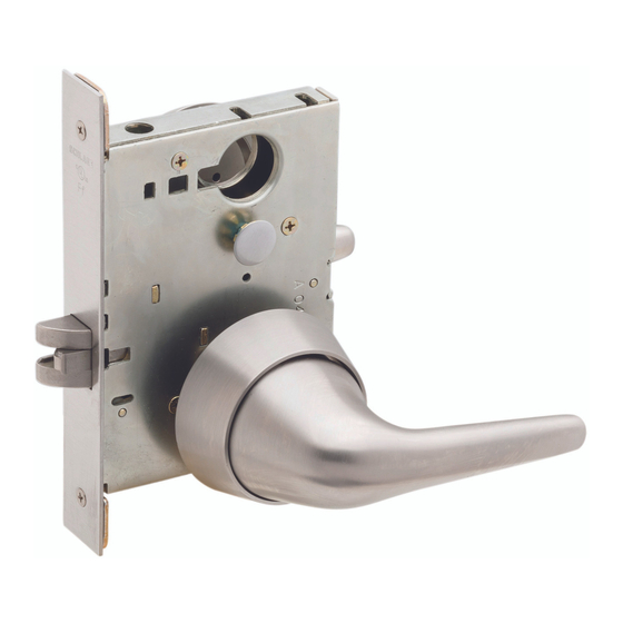
Knob and Rose Trim
For Knob and Escutcheon Trim see page 7.
Check the door preparation dimensions with the template included
in the package.
W
A Lockcase and mounting screws
B Spindle and spring
D Mounting posts
F Occupancy indicator (original style)
J Inside thumb turn
K Cylinder, compression ring and spring
L Inside rose
Para el idioma español e en francés, véase la página 13
L/LV9000-Series
K
L
V
Q
Pour la portion française et espagnole voir page 13
Trim options
P
J
Z
B
A
OR
M Outside knob and rose assembly
N Emergency button
P Coin turn
Q Armor front and screws
V Knob mounting plate
W Inside knob
Z Blocking ring
Installation Instructions
F
Z
K
D
N
M
Publicidad

Manuales relacionados para Schlage LV9000 Serie


Resumen de contenidos para Schlage LV9000 Serie
- Página 1 *P518-673* P518-673 L/LV9000-Series Knob and Rose Trim Installation Instructions For Knob and Escutcheon Trim see page 7. Check the door preparation dimensions with the template included in the package. Trim options A Lockcase and mounting screws M Outside knob and rose assembly B Spindle and spring N Emergency button D Mounting posts...
- Página 2 Door Handing Install lock chassis. IMPORTANT! Check lock handing 4⁷⁄₁₆ x 6¹⁄₁₆ x 1" before installation. 113 x 154 x 25 mm If necessary to change handing: 1. Pull out the latch and rotate 180°. 2. Handing screw must be installed on the interior side of the chassis.
- Página 3 For applicable functions, Prepare outside knob install coin turn, emergency assembly for installation. button or indicator. Install outside mounting posts. Coin turn LV functions Fully tighten mounting Privacy posts on screws. Emergency button Install outside knob. Indicator Use correct driver bar Outside L Note: Original indicator...
- Página 4 Install thumb turn, if Install inside mounting plate. applicable. Thumb turn vertical Install inside trim. Place rose over mounting plate assembly. Rose Rotate thumb turn to lock the door and extend the deadbolt. Thread knob bushing onto mounting plate. Bushing Install thumb turn with two screws.
- Página 5 Refer to the L-Series Service Manual or *Use blocking ring with double cylinders, current Schlage Commercial Price Book specific FSIC, SFIC applications and for details. some door thicknesses. Refer to the L-Series Service Manual or current...
-
Página 6: Troubleshooting
Tighten screws. Install armor front. Tighten two mounting screws. Tighten cylinder mounting screw if necessary. Mounting screw Cylinder mounting screw Mounting screw Troubleshooting Problem Cause Solution Outside knob allows Handing screw may not Check the handing screw immediate egress and be installed correctly. - Página 7 L/LV9000-Series Knob and Escutcheon Trim Installation Instructions Check the door preparation dimensions with the template included in the package. A Lockcase and mounting screws Q Armor front and screws B Spindle and spring S Outside knob and escutcheon assembly D Mounting posts T Inside escutcheon and screws J Thumb turn V Knob mounting plate...
- Página 8 Door Handing Install lock chassis. IMPORTANT! Check lock handing before installation. 4⁷⁄₁₆ x 6¹⁄₁₆ x 1" 113 x 154 x 25 mm If necessary to change handing: 1. Pull out the latch and rotate 180° (if necessary). 2. Handing screw must be installed on the interior side of the chassis.
- Página 9 Prepare outside knob Install outside trim. assembly for installation. IMPORTANT: For concealed Install outside mounting posts. cylinder option only (not shown), install cylinder(s) BEFORE installing escutcheon(s). For cylinder trim, see step 7. Knob only LV functions Fully tighten mounting posts on screws. Exterior Privacy Exterior...
- Página 10 Install inside mounting plate. Install inside trim. IMPORTANT: For concealed Thread bushing onto cylinder option only, install mounting plate. cylinder(s) BEFORE installing escutcheon(s). For cylinder trim, Bushing see step 7. Install escutcheon over mounting plate assembly. Knob only Tighten bushing with spanner wrench (included).
- Página 11 Install outside and inside cylinder(s), if applicable. Outside cylinder Inside cylinder L IMPORTANT: For concealed L IMPORTANT: For concealed cylinder option only (not shown), cylinder option only (not shown), install cylinder(s) BEFORE install cylinder(s) BEFORE installing escutcheon(s). installing escutcheon(s). Install outside escutcheon assembly. Install escutcheon over mounting plate assembly.
- Página 12 Tighten screws. Install armor front. Tighten two mounting screws. Tighten cylinder mounting screw if necessary. Mounting screw Cylinder mounting screw Mounting screw Troubleshooting Problem Cause Solution Outside knob allows Handing screw may not Check the handing screw immediate egress and be installed correctly.
- Página 13 L/LV9000-Series Manija y Embellecedor Instrucciones de Instalación Instructions d’Installation Para manija y escudo, vea a página 21. Levier et Rosette Pour levier y entrée de serrure, voir la página 21. Compruebe las dimensiones de preparación de la puerta con la plantilla incluida en el paquete.
- Página 14 Orientación de la puerta Sens de déplacement de la porte ¡IMPORTANTE! Compruebe el lado IMPORTANT! Vérifiez si la serrure de la cerradura antes de la est pour droitier ou gaucher avant de instalación. l’installer. Si es necesario para cambiar S’il est nécessaire pour changer la el lado: main d’ouverture : 1.
- Página 15 Preparar el ensamble de Instale el chasis de la la perilla exterior para su cerradura. instalación. Installez le bâti de la serrure. Préparez l’ensemble du bouton extérieur pour 4⁷⁄₁₆ x 6¹⁄₁₆ x 1" l’installation. 113 x 154 x 25 mm Instale los postes exteriors de montaje.
- Página 16 Instale el giro con moneda, el botón de emergencia o el indicador (si corresponde). Installez la barrette à fente, le bouton d’urgence ou l’indicateur (s’il y a lieu). Indicador Giro con moneda Indicateur Barrette à fente Privacidad Intimité Utilice la barra impulsora correcta Botón de Utiliser le barre de transmision correcte emergencia...
- Página 17 Instale dentro de la placa de Ajuste el cojinete con la llave montaje. expansora (incluido). Installez à l’intérieur de la Serrez la bague avec la clef à plaque de montage. écrous (inclus). Instale la borde interior. Installez la garniture intérieur. Instale la embellecedor sobre la placa de montaje.
- Página 18 Instale el giro manual interior si corresponde. Installez la barrette tournante intérieur s'il y a lieu. Mariposa se coloca vertical Le tourniquet est verticale placée Gire la perilla para bloquear la puerta y extender el cerrojo. Pivotez la barrette tournante pour verrouiller la porte et déployer le pêne dormant.
- Página 19 Manual de servicio de la Serie L o el Libro actual de precios comerciales de Use el anillo de bloqueo con Schlage para obtener más información. aplicaciones específicas de FSIC y SFIC de doble cilindro, y con algunos *Utilisez l’anneau de blocage avec espesores de puertas.
-
Página 20: Detección De Problemas / Dépannage
Ajuste los tornillos. Instale el frente del blindaje. Installez l’armure de serrure Serrez les vis. avant. Apretarlo dos tornillos de montaje. Apretarlo tornillos de montaje del cilindro si necesaria. Serrer deux vis de montage. Serrer les vis de montage du cylindre si nécessaire. - Página 21 L/LV9000-Series Manija y Escudo Instrucciones de Instalación Levier et Entrée de Serrure Instructions d’Installation Compruebe las dimensiones de preparación de la puerta con la plantilla incluida en el paquete. Vérifiez les dimensions de préparation de la porte à l’aide du gabarit inclus dans l’emballage.
- Página 22 Orientación de la puerta Sens de déplacement de la porte ¡IMPORTANTE! Compruebe el lado IMPORTANT! Vérifiez si la serrure de la cerradura antes de la est pour droitier ou gaucher avant de instalación. l’installer. Si es necesario para cambiar S’il est nécessaire pour changer la el lado: main d’ouverture : 1.
- Página 23 Preparar el ensamble de Instale el chasis de la la manija exterior para su cerradura. instalación. Installez le bâti de la serrure. Préparez l’ensemble du levier extérieur pour l’installation. Instale los postes exteriors de 4⁷⁄₁₆ x 6¹⁄₁₆ x 1" 113 x 154 x 25 mm montaje.
- Página 24 Instale la borde exterior. Installez la garniture extérieur. IMPORTANTE: Solo para el cilindro oculto opcional (no Giro con moneda se muestra), instale el (los) Barrette à fente cilindro(s) ANTES de instalar el escudo. Para los cilindros, ver paso 7. IMPORTANT: Seullement pour le cylindre dissimulé...
- Página 25 Instale la borde interior. Installez la garniture intérieur. IMPORTANTE: Solo para el cilindro oculto opcional (no se muestra), instale el (los) cilindro(s) ANTES de instalar el escudo. Para los cilindros, ver paso 7. IMPORTANT: Seullement pour le cylindre dissimulé (non illustré), installer le(s) cylindre(s) AVANT de poser le(s) entrées de serrure.
- Página 26 Instale el cilindro o los cilindros, si corresponde. Installez le cylindre ou des cylindres, s'il y a lieu. IMPORTANTE: Solo para el cilindro oculto opcional (no se muestra), instale el (los) cilindro(s) ANTES de instalar el escudo. IMPORTANT: Seullement pour le cylindre dissimulé (non illustré), installer le(s) cylindre(s) AVANT de poser le(s) entrées de serrure.
- Página 27 IMPORTANTE: Solo para el cilindro oculto opcional (no se muestra), instale el (los) cilindro(s) ANTES de instalar el escudo. IMPORTANT: Seullement pour le cylindre dissimulé (non illustré), installer le(s) cylindre(s) AVANT de poser le(s) entrées de serrure. Cilindro interior Instale el cilindro con el resorte del Cylindre intérieur cilindro como se muestra.
- Página 28 Ajuste los tornillos. Instale el frente del blindaje. Installez l’armure de serrure Serrez les vis avant. Apretarlo dos tornillos de montaje. Apretarlo tornillos de montaje del cilindro si necesaria. Serrer deux vis de montage. Serrer les vis de montage du cylindre si nécessaire.