
Manuales relacionados para Festo 8038802


Resumen de contenidos para Festo 8038802
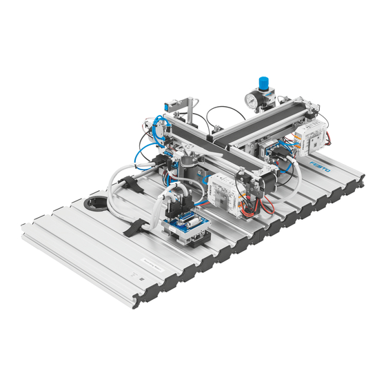
- Página 1 8038802 Separating station ® Stations Kurzbeschreibung Getting started Descripción breve Brève description Festo Didactic 8038803 de/en/es/fr 04/2018 R2.2...
- Página 2 Revision level: 04/2018 Authors: Frank Ebel, Mustafa Ersoy Layout: 04/2018, Suanne Durz © Festo Didactic SE, Rechbergstraße 3, 73770 Denkendorf, Germany, 2018 +49 711 3467-0 www.festo-didactic.com +49 711 34754-88500 did@festo.com Weitergabe sowie Vervielfältigung dieses Dokuments, Verwertung und Mitteilung seines Inhalts verboten, soweit nicht ausdrücklich gestattet.
-
Página 3: Tabla De Contenido
Ablaufbeschreibung _______________________________________________________________ 17 Inbetriebnahme __________________________________________________________________ 19 10.1 Arbeitsplatz ______________________________________________________________________ 19 10.2 Montage von Profilplatte und Bedienpult ______________________________________________ 20 10.3 Kabelverbindungen ________________________________________________________________ 20 10.4 Spannungsversorgung _____________________________________________________________ 21 10.5 SPS Programme laden _____________________________________________________________ 21 10.6 Ablauf starten ____________________________________________________________________ 21 © Festo Didactic 8038803... - Página 4 Inhalt Wartung und Pflege _______________________________________________________________ 22 Weitere Informationen und Aktualisierungen __________________________________________ 22 © Festo Didactic 8038803...
-
Página 5: Allgemeine Voraussetzungen Zum Betreiben Der Geräte
2 Piktogramme Dieses Dokument und die beschriebene Hardware enthalten Hinweise auf mögliche Gefahren, die bei unsachgemäßem Einsatz des Systems auftreten können. Folgende Piktogramme werden verwendet: Warnung … bedeutet, dass bei Missachten schwerer Personen- oder Sachschaden entstehen kann. © Festo Didactic 8038803... -
Página 6: Bestimmungsgemäße Verwendung
Regeln gebaut. Dennoch können bei unsachgemäßer Verwendung Gefahren für Leib und Leben des Benutzers oder Dritter und Beeinträchtigungen der Komponenten entstehen. Das Lernsystem von Festo Didactic ist ausschließlich für die Aus- und Weiterbildung im Bereich Automatisierung und Technik entwickelt und hergestellt. Das Ausbildungsunternehmen und/oder die Ausbildenden hat/haben dafür Sorge zu tragen, dass die Auszubildenden die Sicherheitsvorkehrungen, die... -
Página 7: Für Ihre Sicherheit
Stand der Technik und den anerkannten sicherheitstechnischen Regeln gebaut. Dennoch können bei ihrer Verwendung Gefahren für Leib und Leben des Benutzers oder Dritter bzw. Beeinträchtigungen an der Maschine oder an anderen Sachwerten entstehen. © Festo Didactic 8038803... -
Página 8: Sicher Arbeiten
Benutzen Sie zur Betätigung der Grenztaster ein Werkzeug, z. B. einen Schraubendreher. • Stellen Sie alle Komponenten so auf, dass das Betätigen von Schaltern und Trenneinrichtungen nicht erschwert wird. • Beachten Sie Angaben zur Platzierung der Komponenten. © Festo Didactic 8038803... - Página 9 – Einige Geräte haben einen hohen Ableitstrom. Diese Geräte müssen zusätzlich mit einem Schutzleiter geerdet werden. • Wenn in den Technischen Daten nicht anders angegeben, besitzt das Gerät keine integrierte Sicherung. • Ziehen Sie beim Abbauen der Verbindungsleitungen nur an den Sicherheitssteckern, nicht an den Leitungen. © Festo Didactic 8038803...
- Página 10 – Lärm durch ausströmende Druckluft kann schädlich für das Gehör sein. Reduzieren Sie den Lärm durch den Einsatz von Schalldämpfern oder tragen Sie einen Gehörschutz, falls der Lärm sich nicht vermeiden lässt. – Alle Abluftanschlüsse der Komponenten der Gerätesätze sind mit Schalldämpfern versehen. Entfernen Sie diese Schalldämpfer nicht. © Festo Didactic 8038803...
-
Página 11: Technische Daten
Änderungen vorbehalten 5.2 Kontaktbelegungstabelle Digital Funktion SysLink Farbe Benennung grau-rosa Werkstück bei Bandanfang rot-blau Werkstück bei Bandzwischenposition weiß-grün Werkstück nicht bei Bandende braun-grün Abstandssensor (Signal Schaltausgang) Weiß-grün Werkstück am Bandanfang braun-gelb Werkstück am Bandende weiß-gelb grau-braun © Festo Didactic 8038803... - Página 12 Bei allen Vorzugsvarianten SPS sind Kabelbrücken von NOT-AUS auf Bit 1.5 gesteckt. Analog Funktion D-Sub Farbe Benennung AIn0 Abstandssensor (analoger Ausgang) AIn1 blau AIn2 weiß-grün AIn3 rot-blau AOut0 weiß AOut1 braun GND A grün GND B rosa © Festo Didactic 8038803...
-
Página 13: Transport/Auspacken/Lieferumfang
Die Transportbox darf ausschließlich mit geeigneten Hubwagen oder Gabelstaplern transportiert werden. Die Transportbox muss gegen Umfallen und Herunterfallen gesichert sein. Transportschäden sind unverzüglich dem Spediteur und Festo Didactic zu melden. 6.2 Auspacken Beim Auspacken der Station das Füllmaterial der Transportbox vorsichtig entfernen. Beim Auspacken der Station darauf achten, dass keine Aufbauten der Station beschädigt werden. -
Página 14: Aufbau
Abholstelle am Ende von Transportband 1 bzw. zu einer nachfolgenden Station (0° versetzt) weitergeleitet oder auf Transportband 2 aussortiert bzw. einer weiteren Folgestation (90° versetzt) zugeführt. Die Werkstücke müssen einzeln laufen, damit die Unterscheidung der Werkstücke und die Schaltvorgänge der Weiche nicht behindert werden. © Festo Didactic 8038803... -
Página 15: Das Modul Band 1
Bandanfang, vor der Weiche und am Bandende erfolgt durch optische Näherungsschalter mit Lichtleitern. Der Antrieb des Gurtbandes erfolgt durch einen Gleichstrom-Getriebemotor. Durch einen angebauten Elektromagneten (Drehmagnet) mit Weiche können die Werkstücke ausgeschleust werden. Über einem Stopperzylinder ist ein Analogsensor verbaut, welcher die Orientierung der Werkstücke prüfen kann. © Festo Didactic 8038803... -
Página 16: Das Modul Band 2
Das Modul ist komplett aufgebaut. Durch den angebauten Motorcontroller ist Rechts- und Linkslauf möglich. Das Modul Band dient zum Transport und zum Puffern der Werkstücke. Der Nachweis der Werkstücke am Bandanfang und am Bandende erfolgt durch optische Näherungsschalter mit Lichtleitern. Der Antrieb des Gurtbandes erfolgt durch einen Gleichstrom-Getriebemotor. © Festo Didactic 8038803... -
Página 17: Funktion
Abstand zum Messtisch von ca. 70 mm einzustellen und den Sensor mit einem Winkel von 4-7° zu befestigen. 9 Ablaufbeschreibung Startvoraussetzung • Kein Werkstück auf beiden Bändern Ausgangsstellung • Stopper ausgefahren • Weiche eingefahren • Bandmotoren aus © Festo Didactic 8038803... - Página 18 Leuchtmelder Q1 eingeschaltet. Die Werkstücke müssen entfernt werden und die Station kann wieder referenziert werden. Hinweis Falls kein Sensorsignal innerhalb von 300s eintritt, schaltet das Transportband automatisch ab und die Station geht auf „Störung“ (Leuchtmelder Q1 = 1). © Festo Didactic 8038803...
-
Página 19: Inbetriebnahme
SPS Board mit 16 digitalen Ein- und Ausgängen • ein Netzgerät 24 V DC, 4 A ≤ 100 W • eine Druckluftversorgung mit 600 kPa (6 bar) • einen PC mit installierter SPS Programmiersoftware • zwei E/A-Kabel (SysLink) © Festo Didactic 8038803... -
Página 20: Montage Von Profilplatte Und Bedienpult
SysLink Kabel mit der SysLink Buchse des Bedienpults. 3. SPS Board – Netzgerät Stecken Sie die 4 mm Sicherheitsstecker in die Buchsen des Netzgerätes. 4. PC – SPS Verbinden Sie Ihren PC durch ein Programmierkabel mit der SPS. © Festo Didactic 8038803... -
Página 21: Spannungsversorgung
Bei einer Kombination mehrerer Stationen gilt: Richten der einzelnen Stationen erfolgt entgegen dem Materialfluss. • Der Leuchtmelder “Puffer voll“ leuchtet, wenn sich 6 Werkstücke auf dem Transportband 2 befinden. Entfernen Sie die Werkstücke und führen Sie einen Resetvorgang durch. © Festo Didactic 8038803... -
Página 22: Wartung Und Pflege
Tuch oder Pinsel gereinigt werden. Hinweis Es dürfen keine aggressiven oder scheuernden Reinigungsmittel verwendet werden. 12 Weitere Informationen und Aktualisierungen Weiter Informationen und Aktualisierungen zur Technischen Dokumentation der MPS Stationen finden Sie im Internet unter der Adresse: www.ip.festo-didactic.com © Festo Didactic 8038803... - Página 23 Workstation ______________________________________________________________________ 39 10.2 Mounting the profile plate and the control console ______________________________________ 40 10.3 Cable connections _________________________________________________________________ 40 10.4 Power supply _____________________________________________________________________ 41 10.5 Loading the PLC program ___________________________________________________________ 41 10.6 Starting the sequence ______________________________________________________________ 41 © Festo Didactic 8038803...
- Página 24 Table of contents Maintenance and care _____________________________________________________________ 42 Further information and updates ____________________________________________________ 42 © Festo Didactic 8038803...
-
Página 25: General Requirements For Operating The Devices
Protective earth must always be connected first (before voltage), and must always be disconnected last (after voltage). • If not otherwise specified in the technical data, the device is not equipped with an integrated fuse. © Festo Didactic 8038803... -
Página 26: Pictograms
Festo Didactic hereby excludes any and all liability for damages suffered by trainees, the training company and/or any third parties, which occur during use of the equipment sets in situations which serve any purpose other than training and/or vocational education, unless such damages have been caused by Festo Didactic due to malicious intent or gross negligence. -
Página 27: For Your Safety
The MPS Nevertheless, life and limb of the user and third parties may be endangered, and the machine or other property may be damaged during its use. © Festo Didactic 8038803... -
Página 28: Working Safely
Use a tool to actuate the limit switches, for example a screwdriver. • Set all components up so that activation of switches and disconnectors is not made difficult. • Follow to the instructions regarding positioning of the components. © Festo Didactic 8038803... - Página 29 • The device is not equipped with an integrated fuse unless specified otherwise in the technical data. • Always pull on the plug when disconnecting connecting cables; never pull the cable. © Festo Didactic 8038803...
- Página 30 – Noise caused by escaping compressed air may damage your hearing. Reduce noise by using silencers, or wear hearing protection if noise cannot be avoided. – All of the exhaust ports of the components included in the equipment set are equipped with silencers. Do not remove these silencers. © Festo Didactic 8038803...
-
Página 31: Technical Data
Workpiece at beginning of conveyor Red-blue Workpiece at beginning of conveyor White-green Workpiece not at end of conveyor Brown-green Distance sensor (switching output signal) White-green Workpiece at beginning of conveyor 2 Brown-yellow Workpiece at end of conveyor 2 White-yellow Grey-brown © Festo Didactic 8038803... - Página 32 Cable jumpers are connected from emergency off to bit 1.5 on all PLC variants. Analogue Function D-Sub Colour Designation AIn0 Distance sensor (analogue output signal) AIn1 Blue AIn2 White-green AIn3 Red-blue AOut0 White AOut1 Brown GND A Green GND B Pink © Festo Didactic 8038803...
-
Página 33: Transport, Unpacking, Scope Of Delivery
Examine the station for possible damage after unpacking. The freight forwarder and Festo Didactic must be notified of any damage without delay. 6.3 Scope of delivery Check delivered items against the delivery note and the purchase order. Festo Didactic must be notified of any discrepancies without delay. © Festo Didactic 8038803... -
Página 34: Layout
1 or a subsequent station (0° staggered) or be sorted out onto conveyor belt 2 or be transported to a further subsequent station (90° staggered). The workpieces must proceed individually so as not to impair the differentiating of workpieces and the switching functions of the branch.14 © Festo Didactic 8038803... -
Página 35: The Conveyor Module 1
The conveyor belt is driven by a DC gear motor The workpieces can be ejected by an attached solenoid with deflector. An analog sensor is attached via a stopper cylinder which is capable of checking the workpiece’s orientation. © Festo Didactic 8038803... -
Página 36: The Conveyor Module 2
The Conveyor module is used to transport and buffer workpieces. Optical proximity switches with fibre-optic cables are used to check that workpieces are present at the beginning and at the end of the conveyor. The conveyor belt is driven by a DC gear motor. © Festo Didactic 8038803... -
Página 37: Function
70 mm from the measuring table and to attach the sensor at an angle of 4 to 7°. 9 Sequence description Start prerequisites • No workpiece at start of conveyor Initial position • Stopper advanced • Separator retracted • Conveyor motors off © Festo Didactic 8038803... - Página 38 Q1 is switched on. The workpieces have to be removed and the station can once again be homed. Note If no sensor signal is received within 300 s, the conveyor belt is switched off automatically and the station is switched to the “error” status (signal lamp Q1 = 1). © Festo Didactic 8038803...
-
Página 39: Commissioning
A PLC board with 16 digital inputs and outputs • A power supply unit: 24 V DC, 4.5 A • Compressed air supply: 600 kPa (6 bar) • A PC with installed PLC programming software • Two I/O cables (SysLink) © Festo Didactic 8038803... -
Página 40: Mounting The Profile Plate And The Control Console
3. PLC board to power supply unit Insert the 4 mm safety plug into the socket on the power supply unit. 4. PC to PLC Connect your PC to the PLC via a programming cable. © Festo Didactic 8038803... -
Página 41: Power Supply
The individual stations are aligned in the order opposite the direction of material flow. • The “buffer full” signal lamp lights up wen 6 workpieces are located on conveyor belt 2. Remove the workpieces and execute the reset procedure. © Festo Didactic 8038803... -
Página 42: Maintenance And Care
The entire station Note Do not use aggressive or abrasive cleaning agents. 12 Further information and updates Further information and updates of the technical documentation for the MPS stations is available on the following website: www.ip.festo-didactic.com © Festo Didactic 8038803... - Página 43 Montaje de la placa perfilada y del panel de mando ______________________________________ 60 10.3 Conexiones de cable _______________________________________________________________ 60 10.4 Fuente de alimentación ____________________________________________________________ 61 10.5 Cargar programas PLC _____________________________________________________________ 61 10.6 Inicio de la secuencia ______________________________________________________________ 61 © Festo Didactic 8038803...
- Página 44 Índice Cuidados y mantenimiento _________________________________________________________ 62 Informaciones complementarias y actualizaciones______________________________________ 62 © Festo Didactic 8038803...
-
Página 45: Condiciones Generales Para El Uso De Los Equipos
Además, debe desconectarse en último lugar, después de desconectar la tensión. • Si no se indica lo contrario en los datos técnicos, el aparato no contiene un fusible integrado. © Festo Didactic 8038803... -
Página 46: Pictogramas
El sistema para la enseñanza de Festo Didactic ha sido concebido exclusivamente para la formación y el perfeccionamiento profesional en materia de sistemas y técnicas de automatización industrial. La empresa u organismo encargado de impartir las clases y/o los instructores deben velar por que los alumnos/aprendices respeten las indicaciones de seguridad que se describen en el presente manual. -
Página 47: Indicaciones De Seguridad
A pesar de ello, su utilización puede generar peligros que podrían afectar la integridad física o poner en peligro la vida de los usuarios o de terceros, así como también provocar daños en la máquina u otros daños materiales. © Festo Didactic 8038803... -
Página 48: Trabajar Con Seguridad
Para accionar los detectores de posiciones finales, utilice una herramienta (por ejemplo, un destornillador). • Efectúe el montaje de todos los componentes de tal manera que pueda acceder fácilmente a los interruptores y a las conexiones. • Respete las indicaciones sobre el posicionamiento de los componentes. © Festo Didactic 8038803... - Página 49 • Si no se indica lo contrario en los datos técnicos, el aparato no contiene un fusible integrado. • Al desconectar los cables, tire únicamente de los conectores de seguridad, nunca de los cables. © Festo Didactic 8038803...
- Página 50 Reduzca el nivel de ruidos utilizando silenciadores, o bien tapones para los oídos si no fuese posible evitar los ruidos. – Todas las conexiones de escape de aire deberán estar provistos de silenciadores. No retire esos silenciadores. © Festo Didactic 8038803...
-
Página 51: Datos Técnicos
Marrón y verde Sensor de distancia (señal en salida de conmutación) Blanco y verde Pieza a manipular en el inicio de la cinta Marrón y amarillo Pieza al final de la cinta Blanco y amarillo Gris y marrón © Festo Didactic 8038803... - Página 52 En todas las variantes de PLC, los cables que puentean la parada de emergencia están conectados a bit 1.5. Analógico Función Sub-D Color Denominación AIn0 Rojo Sensor de distancia (salida analógica) AIn1 Azul AIn2 Blanco y verde AIn3 Rojo y azul AOut0 Blanco AOut1 Marrón GND A Verde GND B Rosa © Festo Didactic 8038803...
-
Página 53: Transporte / Desembalaje / Dotación Del Suministro
La caja deberá moverse únicamente utilizando una carretilla elevadora apropiada. La caja deberá estar asegurada de tal manera que no pueda caerse. Cualquier daño ocurrido durante el transporte deberá notificarse de inmediato al transportista y a Festo Didactic. 6.2 Desembalaje Para sacar la estación de su caja de transporte, deberá... -
Página 54: Construcción
2 o se pasan a una estación siguiente (90° desplazamiento). Las piezas deben avanzar individualmente, para no obstruir la operación de diferenciación de las piezas y el funcionamiento del desvío. © Festo Didactic 8038803... -
Página 55: Módulo De Cinta De Transporte 1
A través de electroimanes montados (imán giratorio) con el derivador se pueden expulsar las piezas. La cinta se impulsa con un motor reductor DC. Encima de un cilindro de tope está montado un sensor analógico que puede comprobar la orientación de la pieza. © Festo Didactic 8038803... -
Página 56: Módulo De Cinta De Transporte 2
El módulo transportador sirve de zona de acumulación y para el transporte de las piezas a manipular. Las piezas a manipular se detectan mediante sensores de proximidad ópticos con conductores de fibra óptica al inicio y al final de la cinta. La cinta se impulsa con un motor reductor DC. © Festo Didactic 8038803... -
Página 57: Funcionamiento
ángulo de entre 4 y 7º. 9 Descripción de las secuencias Condiciones iniciales para la activación • Ausencia de piezas al inicio de la cinta Posición inicial • Tope extendido • Desvío en posición retraída • Motores de las cintas desconectados © Festo Didactic 8038803... - Página 58 Q1. Se tienen que retirar las piezas y la estación puede volver a ser referenciada. Nota En caso de que no se produzca ninguna señal del sensor en 300 segundos, la cinta transportadora se desconecta automáticamente y la estación se coloca en "Fallo" (indicador luminoso Q1 = 1). © Festo Didactic 8038803...
-
Página 59: Puesta A Punto
Una fuente de alimentación 24 V CC, 4 A ≤ 100 W • Una alimentación de aire comprimido con 600 kPa (6 bar) • Un PC con software de programación PLC instalado • Dos cables E/S (SysLink) © Festo Didactic 8038803... -
Página 60: Montaje De La Placa Perfilada Y Del Panel De Mando
3. Placa PLC – Unidad de alimentación eléctrica Conecte los conectores de seguridad de 4 mm a los conectores de la unidad de alimentación. 4. PC – PLC Conecte el PC al PLC mediante un cable de programación. © Festo Didactic 8038803... -
Página 61: Fuente De Alimentación
La alineación de cada una de las estaciones se efectúa siguiendo el orden contrario al flujo del material. • El indicador luminoso "Buffer Full" se ilumina cuando hay seis piezas a manipular en el transportador 2. Retire las piezas y efectúe el proceso de reinicio. © Festo Didactic 8038803... -
Página 62: Cuidados Y Mantenimiento
No deberán utilizarse detergentes agresivos o abrasivos. 12 Informaciones complementarias y actualizaciones En la dirección Internet que se indica a continuación se ofrecen informaciones complementarias y actualizaciones de la documentación técnica de las estaciones MPS ® www.ip.festo-didactic.com © Festo Didactic 8038803... - Página 63 Poste de travail ___________________________________________________________________ 79 10.2 Montage de la plaque profilée et du pupitre de commande ________________________________ 80 10.3 Câblage _________________________________________________________________________ 80 10.4 Alimentation électrique ____________________________________________________________ 81 10.5 Chargement des programmes API ____________________________________________________ 81 10.6 Démarrage du cycle _______________________________________________________________ 81 © Festo Didactic 8038803...
- Página 64 Table des matières Maintenance et entretien __________________________________________________________ 82 Informations complémentaires et mises à jour _________________________________________ 82 © Festo Didactic 8038803...
-
Página 65: Conditions Générales D'exploitation Des Appareils
La terre de protection doit toujours être raccordée en premier (avant la tension) et être débranchée en dernier (après coupure de la tension). • Sauf indications contraires dans les caractéristiques techniques, l'appareil ne possède pas de fusible intégré. © Festo Didactic 8038803... -
Página 66: Pictogrammes
Le système de formation de Festo Didactic est exclusivement destiné à la formation initiale et continue dans le domaine de l’automatisation et de la technique. Il incombe à l’établissement de formation et/ou aux formateurs de faire respecter par les étudiants les consignes de sécurité... -
Página 67: Pour Votre Sécurité
Son utilisation peut néanmoins mettre en danger la vie et la santé de l’utilisateur ou de tiers ainsi qu’affecter l’intégrité de la machine ou d’autres biens. © Festo Didactic 8038803... -
Página 68: Travailler En Toute Sécurité
Utilisez un outil, par exemple un tournevis, pour actionner les capteurs de fin de course. • Installez les composants de telle sorte qu'ils ne gênent pas l'actionnement d'interrupteurs ni de dispositifs de sectionnement de l'alimentation. • Notez les indications concernant l'implantation des composants. © Festo Didactic 8038803... - Página 69 à la terre par un fil de protection. • Sauf indications contraires dans les caractéristiques techniques, l'appareil ne possède pas de fusible intégré. • Pour débrancher les câbles de liaison, tirez sur les connecteurs, pas sur les câbles. © Festo Didactic 8038803...
- Página 70 – Le bruit produit par l'échappement d'air comprimé peut nuire à l'ouïe. Réduisez le bruit en utilisant des silencieux ou portez un casque anti-bruit si le bruit est inévitable. – Équipez tous les orifices d'échappement des jeux d'équipement de silencieux. Ne retirez pas ces silencieux. © Festo Didactic 8038803...
-
Página 71: Caractéristiques Techniques
Pièce en début de convoyeur rouge/bleu Pièce en début de convoyeur blanc/vert Pièce pas en fin de convoyeur marron/vert Capteur de distance (signal de sortie TOR) blanc/vert Pièce en début de convoyeur marron/jaune Pièce en fin de convoyeur blanc/jaune gris/marron © Festo Didactic 8038803... - Página 72 Sur toutes les variantes préférentielles API, des cavaliers sont enfichés de ARRÊT D’URGENCE à bit 1.5. Analogique Fonction Sub-D Couleur Désignation AIn0 rouge Capteur de distance (sortie analogique) AIn1 bleu AIn2 blanc/vert AIn3 rouge/bleu AOut0 blanc AOut1 marron GND A vert GND B rose © Festo Didactic 8038803...
-
Página 73: Transport/Déballage/Fourniture
La caisse doit être exclusivement manutentionnée au moyen de transpalettes ou de chariots à fourche appropriés. Il convient de faire en sorte que la caisse ne puisse se renverser ni tomber. Tout dommage dû au transport doit être immédiatement signalé au transporteur et à Festo Didactic. 6.2 Déballage Au déballage de la station, retirez avec précaution le matériau de calage de la caisse. -
Página 74: Présentation
1 ou à une station aval (située dans l'axe), soit évacuées vers le convoyeur 2 ou acheminées à une autre station aval (à 90°). Les pièces doivent défiler une à une afin de ne pas entraver la distinction des pièces ni les opérations de commutation de l'aiguillage. © Festo Didactic 8038803... -
Página 75: Le Module Convoyeur 1
La présence des pièces en début de convoyeur, devant l'aiguillage et en fin de convoyeur est détectée par des capteurs de proximité optiques à fibres optiques. L'électroaimant incorporé (solénoïde rotatif) avec aiguillage permet d'évacuer les pièces. Un capteur analogique, monté au-dessus d'un vérin stoppeur, permet de contrôler l'orientation des pièces. © Festo Didactic 8038803... -
Página 76: Le Module Convoyeur 2
Le module convoyeur sert au transport et au stockage temporaire des pièces. La détection des pièces en début de convoyeur et en fin de convoyeur est assurée par des capteurs de proximité optiques à fibres optiques. L'entraînement du convoyeur s'opère par motoréducteur à courant continu. © Festo Didactic 8038803... -
Página 77: Fonctionnement
70 mm par rapport à la table de mesure et de fixer le capteur à un angle de 4-7°. 9 Description du cycle Prérequis au démarrage • Pas de pièce en début de convoyeur Position initiale • Stoppeur sorti • Aiguillage rentré • Moteurs de bande désactivés © Festo Didactic 8038803... - Página 78 Q1 s'allume. Les pièces doivent être retirées et la station peut à nouveau être mise en référence. Nota Si aucun signal de détecteur n'est émis dans les 300 s, le convoyeur s'arrête automatiquement et la station passe en mode « dysfonctionnement » (voyant Q1 = 1). © Festo Didactic 8038803...
-
Página 79: Mise En Service
24 V DC, 4 A ≤ 100 W • une alimentation en air comprimé à 600 kPa (6 bar), • un PC sur lequel est installé un logiciel de programmation d’API et • deux câbles d’E/S (SysLink). © Festo Didactic 8038803... -
Página 80: Montage De La Plaque Profilée Et Du Pupitre De Commande
3. Carte API – Bloc d’alimentation Branchez les fiches de sécurité de 4 mm aux douilles du bloc d'alimentation. 4. PC – API Reliez votre PC à l'API par un câble de programmation. © Festo Didactic 8038803... -
Página 81: Alimentation Électrique
Si plusieurs stations sont combinées, la mise en référence des différentes stations s'opère dans le sens opposé au flux matière. • Le voyant « Tampon plein » s'allume lorsque 6 pièces se trouvent sur le convoyeur 2. Retirez les pièces et exécutez une réinitialisation. © Festo Didactic 8038803... -
Página 82: Maintenance Et Entretien
Aucun produit de nettoyage agressif ou abrasif ne doit être utilisé. 12 Informations complémentaires et mises à jour La documentation technique des stations MPS® fait l’objet d’informations complémentaires et mises à jour que vous trouverez sur Internet à l’adresse : www.ip.festo-didactic.com © Festo Didactic 8038803... - Página 84 Festo Didactic SE Rechbergstraße 3 73770 Denkendorf Germany +49 711 3467-0 www.festo-didactic.com +49 711 34754-88500 did@festo.com...