Tabla de contenido
Publicidad
Idiomas disponibles
Idiomas disponibles
Enlaces rápidos
MK 35-31
MK 35-32
808495-03
DE
Betriebsanleitung
Kondensatableiter MK 35/31, MK35/32
EN
Installation Instructions
Steam Traps MK35/31, MK 35/32
FR
Instructions de montage et
de mise en service
Purgeurs MK 35/31, MK 35/32
ES
Instrucciones de montaje y servicio
Purgadores automáticos MK 35/31, MK 35/32
IT
Manuale di Istruzioni
Scaricatore di condensa MK 35/31, MK 35/32
Publicidad
Tabla de contenido

Manuales relacionados para GESTRA MK 35-31


Resumen de contenidos para GESTRA MK 35-31
- Página 1 MK 35-31 Betriebsanleitung Kondensatableiter MK 35/31, MK35/32 Installation Instructions MK 35-32 Steam Traps MK35/31, MK 35/32 Instructions de montage et 808495-03 de mise en service Purgeurs MK 35/31, MK 35/32 Instrucciones de montaje y servicio Purgadores automáticos MK 35/31, MK 35/32...
-
Página 2: Bestimmungsgemäßer Gebrauch
Bestimmungsgemäßer Gebrauch Bestimmungsgemäßer Gebrauch Den Kondensatableiter MK 35 nur zur Abführung von Kondensat oder als Dampfentlüfter aus Wasserdampf einsetzen. Sicherheitshinweis Das Gerät darf nur von qualifiziertem Fachpersonal installiert werden. Qualifiziertes Fachpersonal sind Personen, die mit Montage und Inbetriebnahme des Produktes vertraut sind und über die ihrer Tätigkeit entsprechenden Qualifikationen verfügen wie zum Beispiel: Ausbildung als Fachkraft. - Página 3 Gefahr Gefahr Die Armatur steht während des Betriebs unter Druck! Wenn Flanschverbindungen oder Verschlussschrauben gelöst werden, strömt heißes Wasser oder Dampf aus. Schwere Verbrühungen am ganzen Körper sind möglich. Montage- oder Wartungsarbeiten nur bei Anlagendruck null durchführen! Die Armatur ist während des Betriebs heiß! Schwere Verbrennungen an Händen und Armen sind möglich.
- Página 4 Einstufung gemäß Druckgeräte-Richtlinie Einstufung gemäß Artikel 9 Druckgeräte-Richtlinie gasförmig Fluid flüssig Fluidgruppe nein nein Verwendung Ausnahme Kategorie gemäß Artikel 4.3 Nennweite DN 10 - 15 CE-Kennzeichnung nein...
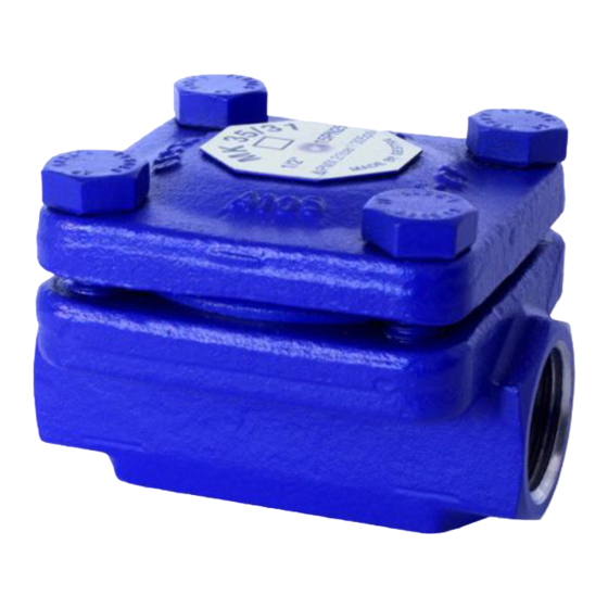
- Página 5 Systembeschreibung Thermischer Kondensatableiter mit korrosionsbeständiger, wasser- schlaggeschützter Mono-Regelmembran und Schmutzfänger. Asbestfreie Gehäusedichtung (Graphit/ CrNi). Einbau in jeder Lage. MK 35-31 mit Tandemabschluss (Doppeldichtung) ■ Speziell für kleine Kondensatmengen. Wahlweise mit Regelmembran 5 N 1 (Normal) oder Regelmembran 5 U 1 (Unterkühlung).
- Página 6 Einbau Einbau 1. Einbaulage beachten. 2. Durchflussrichtung beachten. Der Durchflussrichtungspfeil befindet sich auf dem Ableitergehäuse! 3. Servicemaß berücksichtigen. Wenn der Ableiter fest eingebaut ist, wird zur Demontage der Haube ein Freimaß von mindesten 30 mm benötigt! 4. Kunststoff-Verschlussstopfen entfernen. Die Kunststoff-Verschlussstopfen dienen nur als Transportsicherung! 5.
-
Página 7: Technische Daten
Technische Daten Technische Daten ä , " " ß i ü t i r ° [ ä l ü c i l ) Einsatzgrenzen für den bestimmungsgemäßen Gebrauch. - Página 8 Usage for the intended purpose Usage for the intended purpose Use steam trap MK 35 only for the discharge of condensed water from steam lines or for air venting. Important Safety Note Installation must only be performed by qualified staff. Qualified staff are those persons who –...
- Página 9 Danger Danger The trap is under pressure during operation. When disassembling or opening the trap, or loosening sealing plugs, hot water and steam may escape. This presents the danger of severe burns to the whole body. Installation and maintenance work should only be carried out when the system is depressurized.
- Página 10 Ratings pursuant to article 9 of the PED Ratings pursuant to the PED Fluid liquid Fluid group Exception pursuant Category to article 4.3 Nominal size DN 10 - 15 CE marking ) PED = Pressure Equipment Directive...
-
Página 11: System Description
Thermostatic steam trap with membrane regulator and integral strainer. Corrosion-resistant thermostatic capsule unaffected by waterhammer. Asbestos-free cover gasket (graphite/CrNi). Installation in any position. MK 35-31 with tandem seat (double seat) ■ In particular for low condensate flowrates. Optionally either with standard capsule “5 N 1”... - Página 12 Installation Installation 1. Observe position of installation. 2. Observe direction of flow. The flow direction arrow is located on the trap body. 3. Leave at least 30 mm free space around the equipment for disassembly of the cover at a later date. 4.
-
Página 13: Technical Data
Technical Data Technical Data , " " ° [ l a i ) Specified only for the intended purpose of the equipment. - Página 14 Emploi conformément à l’utilisation prevue Emploi conformément à l’utilisation prevue N’utiliser le purgeur MK 35 que pour l’évacuation de condensat des tuyauteries de vapeur et pour la désaération. Avis important pour la sécurité L’appareil ne doit être installé que par du personnel qualifié. Le personnel doit avoir la qualification nécessaire pour l’installation et la mise en service de l’appareil et posséder la compétence et l’expérience acquise par...
- Página 15 Danger Danger En service le purgeur est sous pression et très chaud. Lors du desserrage des brides ou bouchons, de l’eau bouillante ou de la vapeur peut s’échapper. Il y a risque de brûlures graves sur tout le corps. S’assurer que l’appareil n’est plus sous pression avant d’effectuer le démontage et les travaux d’entretien.
- Página 16 Classification selon la directive concernant Classification selon l’article 9 de la directive concernant les appareils soumis à pression les appareils soumis à pression Fluide Liquide Groupe de fluide Utilisation Exception selon Catégorie article 4.3 Diamètre nominal DN 10 - 15 Marque CE...
-
Página 17: Description Du Système
Description du système Description du système Purgeur thermique à membrane auto-régulatrice (thermostat à vaporisation), résistant à la corrosion et insensible aux coups de bélier. Filtre incorporé. Joint de capot sans amiante (graphite/CrNi). Montage dans n’importe quelle position. MK 35/31 à fermeture tandem (double étanchéité) ■... - Página 18 Installation Installation 1. Tenir compte de la position d’installation. 2. Respecter le sens d’écoulement indiqué sur le corps du purgeur par une flèche. 3. Tenir compte d’une hauteur libre de 30 mm au minimum pour le démontage ultérieur du capot. 4.
-
Página 19: Données Techniques
Données techniques Données techniques u ’ l i t t è , " " é é é é ° [ é f e l l ) Limites en utilisation conforme. -
Página 20: Aplicación Para El Uso Previsto
Aplicación para el uso previsto Aplicación para el uso previsto Utilícese el purgador MK 35 exclusivamente para la evacuación de agua condensada en conductos de vapor y para la desaireación. Advertencia sobre seguridad El purgador sólo debe ser instalado por personal especializado. El personal especializado se limita a personas con formación para instalar y poner en servicio el aparato, disponiendo de la calificación profesional y la experiencia requerida. - Página 21 Peligro Peligro El purgador está bajo presión durante el funcionamiento. Al desmontar o al abrir el purgador o al soltar los tornillos de cierre habrá escape de agua caliente o vapor. Existe el peligro de sufrir severas quemaduras en todo el cuerpo. Realizar el montaje o los trabajos de mantenimiento únicamente cuando el equipo no esté...
- Página 22 Clasificación según artículo 9 de la directriz Clasificación según la directriz de equipos de equipos a presión a presión Tipo de fluido líquido Grupo de fluido sí sí Aplicación Excepción según Clase artículo 4.3 Diámetro nominal DN 10 - 15 Marca CE...
-
Página 23: Descripción De Sistema
Con filtro interior. Junta del cuerpo, sin amianto (grafito/CrNi). Montaje en cualquier posición. MK 35-31 con cierre Tandem (cierre doble) ■ Especial para pequeños caudales de condensado. Alternativamente, con membrana de regulación “5 N1” (N = normal) o membrana de regulación “5 U1”... -
Página 24: Montaje
Montaje Montaje 1. Tener en cuenta la posición de instalación. 2. Hay que considerar la dirección del flujo. La flecha que indica la dirección del flujo está en el cuerpo del purgador. 3. Tener en cuenta un espacio libre de por lo menos 30 mm para el caso que se tenga que desmontar la tapa más adelante. -
Página 25: Datos Técnicos
Datos técnicos Datos técnicos ó i , " " ó i ° [ ó i é f l a i á ó i á r ó i ) Limites de acuerdo con la finalidad especificada. -
Página 26: Avvertenza Di Sicurezza
Corretto impiego Corretto impiego Usare gli scaricatori MK 35 solamente per lo scarico delle condense da linee vapore o per l’ evacuazione di aria. Avvertenza di sicurezza L’ installazione deve essere eseguita da personale qualificato. Per personale qualificato si intendono persone che abbiano: seguito corsi di formazione termotecnica/elettromeccanica ■... - Página 27 Pericolo Pericolo Durante l’esercizio lo scaricatore è sotto pressione ed è molto caldo, attenzione alle probabili scottature. Smontando lo scaricatore o allentando le viti il fluido fuoriesce violentemente con probabili scottature. Questi lavori devono sempre essere eseguiti ad impianto freddo e senza pressione.
- Página 28 Impiego in base PED Impiego in base all’articolo 9 della PED Fluido liquido Gruppi fluidi Impiego Eccezione Categoria all’articolo 4.3 Diametro nom DN 10 - 15 Marcatura CE ) PED = Direttiva Apparecchi in Pressione...
- Página 29 Scaricatore di condensa termostatico con membrana di regolazione resistente alla corrosione ed ai colpi d’ariete. Filtro ad «Y», guarnizioni del coperchio in Grafite/CrNi. Installazione in qualsiasi posizione. MK 35-31 (con chiusura doppia) ■ Adatto per piccole portate. In opzione con membrana standard «5 N 1»...
- Página 30 Installazione Installazione 1. Verificare la posizione di montaggio. 2. Verificare la direzione del flusso. Una freccia è riportata sul corpo dello scaricatore. 3. Per un eventuale smontaggio del coperchio prevedere uno spazio di almeno 30 mm. 4. Togliere i tappi di plastica (sono utilizzati solamente per protezione). 5.
-
Página 31: Dati Tecnici
Dati tecnici Dati tecnici i t i i ’ i r t , " " ° [ ) Limiti d’impiego per il uso appropriato. - Página 32 GESTRA AG Münchener Straße 77 28215 Bremen Germany Telefon +49 421 3503-0 Telefax +49 421 3503-393 E-mail info@de.gestra.com www.gestra.de 808495-03/06-2017cmp · GESTRA AG · Bremen · Printed in Germany...