
Manuales relacionados para Pentair BIOSHIELD PRO


Resumen de contenidos para Pentair BIOSHIELD PRO
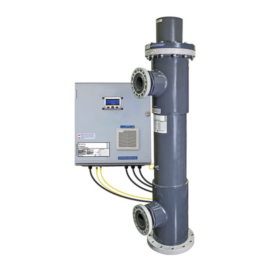
- Página 1 BIOSHIELD ® UV SYSTEM INSTALLATION AND USER'S GUIDE IMPORTANT SAFETY INSTRUCTIONS READ AND FOLLOW ALL INSTRUCTIONS SAVE THESE INSTRUCTIONS...
- Página 2 10951 WEST LOS ANGELES AVE., MOORPARK, CA 93021 • (805) 553-5000 WWW.PENTAIR.COM All indicated Pentair trademarks and logos are property of Pentair. Third party registered and unregistered trademarks and logos are the property of their respective owners. P/N 523573 01/2023...
- Página 3 TABLE OF CONTENTS Section 1: Introduction ..........4 Section 7: Operation ..........17 Section 8: Maintenance ......... 18 General Information ..........4 Glossary ..............4 Routine Inspection ..........18 Section 2: Health and Safety Precautions ..... 5 UV Lamp Replacement ........18 Safety Symbols .............
- Página 4 SECTION 1: INTRODUCTION General Information Pentair Water Pool and Spa, Inc. (Pentair) accepts no responsibility for any problems arising from incorrect In this manual you will find user information for installation, lack of routine maintenance as specified in your BioShield PRO UV System.
- Página 5 IMPORTANT: For your safety the quartz sleeve and/or the than its intended use. The use of attachments not recommended or sold by Pentair may cause unsafe conditions and possibly void any UV lamp in this product may have been broken or damaged during shipping.
- Página 6 SECTION 2: HEALTH AND SAFETY PRECAUTIONS HAZARDOUS SITUATIONS & APPROPRIATE ACTIONS SITUATION LOCATION HAZARD ACTIONS Isolate UV system from water source, shutdown system Lamp or Quartz UV Vessel Burn using external On/ Off switch and lock-out disconnect Sleeve Removal from input power source. Broken Quartz Handle quartz sleeves and UV lamps with extreme care, UV Vessel...
- Página 7 SECTION 3: INSTALLATION Pre-Installation Inspection The UV System consists of: Purpose • Quartz Sleeve Module (QSM) Faceplate (assembled on Vessel) To familiarize the installer/operator with the UV Systems Lines’ components, to assure proper delivery of all the • QSM Faceplate Gasket (assembled on Vessel) system’s components and to inspect each component •...
- Página 8 SECTION 3: INSTALLATION UV Vessel Installation Procedure Purpose IMPORTANT: The installation of the UV system must be carried out in accordance with local regulations and Proper installation of the UV Vessel achieves expected codes. results and ensures safe operation. 1. Install the UV system after the mechanical filtration. Frequency This eliminates debris from entering the vessel and diminishing the unit’s effectiveness, as well as...
- Página 9 SECTION 3: INSTALLATION Vertical Installation 4. Isolation Valves are necessary for vessel removal and chemical cleaning procedure. It is recommended Vertical installation requires the bottom port to be to install the isolation valves in conjunction with a used as the vessel’s inlet and the port closest to the separate set of, matching size &...
- Página 10 SECTION 3: INSTALLATION Quartz Sleeve Installation 2. Carefully slide the quartz sleeve(s) into the Quartz Sleeve Faceplate’s “Quartz Sleeve Module” (QSM) Purpose until quartz sleeve stops (don't push down on quartz sleeve). To thermally protect the UV lamp and isolate it from water.
- Página 11 SECTION 3: INSTALLATION Mounting Power Supplies (Ballasts) The BioShield PRO UV System's power supply should ® always be mounted to a surface which does not expose the power supply to standing water. NOTE: DO NOT mount the power supply in an extremely confined space where heat and moisture can be retained.
- Página 12 SECTION 3: INSTALLATION Flow Switch Interconnect Box and Ballast The recommended position for flow switch installation Locate the ballast cable with the black M12 male is on the outlet of the UV system. Ensure the flow connector. switch is not subject to flow agitation resulting in false Connect the ballast cable to the connector labeled flow conditions.
- Página 13 SECTION 4: MANDATORY WATER TEST Mandatory Water Test 2. Place rolled-up paper towels into the Quartz Sleeve Retaining Nuts. During the water test, the paper Purpose towels may absorb moisture. The presence of any moisture identifies that a quartz sleeve seal failure The Mandatory Water Test identifies a potential quartz (leak) has occurred.
- Página 14 SECTION 5: UV LAMP INSTALLATION Purpose 3. Loosen (not remove) the lamp Water Tight Connector nut (2) to release tension on the lamp cable allowing To instruct the operator how to properly install the UV the cable to slide freely through the adapter. This will lamp(s).
- Página 15 SECTION 5: UV LAMP INSTALLATION Lamp Field Safety Cover Installation 3. Once the cover is in place, tighten the four Retaining Screws down until the cover is snugly held in place. Purpose To instruct the operator how to properly install the 4.
- Página 16 SECTION 6: COMMISSIONING Start-Up Procedure Purpose 1. Confirm that all personnel operating this UV system have thoroughly reviewed these instructions prior to This section contains the necessary steps required operating. to prepare the BioShield PRO UV System for proper ® operation.
- Página 17 SECTION 7: OPERATION Initial Start-Up 1. Verify the white quartz sleeve nuts for the quartz sleeve modules are secure. 2. Turn on pump. 3. Give time for the vessel to fill with water. 4. Energize UV system ballasts. a. The ballast will delay the UV Lamp from illuminating for 25 seconds once flow is above the “On”...
- Página 18 SECTION 8: MAINTENANCE DANGER: OBEY ALL SITE-SPECIFIC SAFETY PROTOCOLS. General risk due to pressurized piping and UV ALWAYS REMOVE STATIC AND DYNAMIC WATER PRESSURE FROM THE UV REACTOR BEFORE DOING ANY MAINTENANCE TASK. vessel! APPLY LOCKOUT/TAGOUT AS NECESSARY TO PREVENT UNEXPECTED EXPOSURE TO HIGH WATER PRESSURE OR PROJECTILES EJECTING FROM THE END PLATE.
- Página 19 SECTION 8: MAINTENANCE Quartz Sleeve Removal WARNING: DO NOT ALLOW REACTOR Purpose QUARTZ SLEEVE ADAPTER NUT TO LOOSEN. To inspect or replace broken quartz sleeve(s) in order to maintain required/expected UV intensity. 3. Unthread the Water Tight Connector Fitting from the White Quartz Sleeve Adapter Nut.
- Página 20 SECTION 8: MAINTENANCE Procedure Quartz Sleeve Cleaning Purpose 1. Unplug the Power Supply Enclosure from the electrical outlet. To manually check and clean quartz sleeve(s). 2. Drain the vessel completely. 3. Remove UV lamp(s). See Page 17 for instructions. Frequency 4.
- Página 21 The removal of this build-up (calcium, etc.) can be carried out with a cleaning pump. Pentair recommends WARNING: If a sleeve nut is removed when there the use of muriatic acid to chemically clean the quartz is dynamic water pressure inside the UV system, the sleeves.
- Página 22 SECTION 8: MAINTENANCE Procedure UV Vessel Disassembly Purpose 1. With the quartz sleeves still installed in the UV vessel, unplug the Power Supply Enclosure from the To disassemble the vessel for internal inspection. electrical outlet. 2. Isolate the UV vessel from the water flow using Frequency the required isolation valves and drain the vessel UV vessel disassembly is only required if a problem...
- Página 23 SECTION 8: MAINTENANCE Procedure 9. Fit the QSM Faceplate Rubber Gasket onto the alignment posts. IMPORTANT: DO NOT Attempt to remove the QSM Faceplate with the quartz sleeves assembled. ALL IMPORTANT: To properly align the QSM Faceplate, lamps and quartz sleeves MUST be removed before set the #1 lamp position (as stamped on the faceplate, disassembling the QSM Faceplate from the UV vessel.
- Página 24 SECTION 9: REPLACEMENT PARTS SYSTEM PART NUMBER ITEM # ITEM DESCRIPTION 523575 523576 523577 523578 523579 523580 NSF SAFETY CAP 523613 523613 523614 523614 523614 523614 QUARTZ SLEEVE QSRA-HDPE RETAINING NUT QUARTZ O-RING EP50-318Z FACEPLATE CLPHO-2-6BF CLPHO-4-6BF CLPHO-4-8BF CLPHO-5-8BF CLPHO-5-10BF CLPHO-6-10BF FACEPLATE GASKET 17-060 17-060...
- Página 25 SECTION 10: SYSTEM SPECIFICATIONS Dimensional Data VESSEL DIMENSIONS (Inches) HEIGHT W/ MAINTENANCE MODEL NO. OFLAMPS FLANGE SIZE CLEARANCE PORT TO PORT VESSEL HEIGHT VESSEL SIZE 523575 4” 114” 43.375 62.375 523576 4” 114” 43.375 62.375 523577 6” 117” 42.125 65.875 523578 6”...
- Página 26 NOTES BioShield® PRO UV System Installation and User's Guide...
- Página 27 BIOSHIELD ® SISTEMA UV GUÍA DE INSTALACIÓN Y MANUAL DE USUARIO INSTRUCCIONES DE SEGURIDAD IMPORTANTES LEA Y SIGA TODAS LAS INSTRUCCIONES GUARDE ESTAS INSTRUCCIONES...
- Página 28 10951 WEST LOS ANGELES AVE., MOORPARK, CA 93021 • (805) 553-5000 WWW.PENTAIR.COM Todas las marcas comerciales y los logotipos de Pentair indicados son propiedad de Pentair. El resto de marcas comerciales y logotipos registrados o sin registrar de terceros son propiedad de sus respectivos propietarios.
- Página 29 ÍNDICE English ................ 1 Sección 7: Funcionamiento ........43 Sección 1: Introducción .........30 Sección 8: Mantenimiento ........44 Información general ..........30 Inspección rutinaria ..........44 Glosario .............. 30 Sustitución de la lámpara UV ......44 Sección 2: Precauciones sobre salud Extracción de la lámpara UV ......44 y seguridad ...........
- Página 30 UV. Siga estrictamente las instrucciones Pentair Water Pool and Spa, Inc. (Pentair) no se hace contenidas en este manual para proteger tanto su salud responsable de ningún problema que pueda surgir y seguridad como la del sistema UV.
- Página 31 El empleo de accesorios no recomendados ni la manga de cuarzo y/o la lámpara de este producto pueden vendidos por Pentair puede dar lugar a condiciones poco haberse dañado o roto durante el envío. Es CRUCIAL seguras, y es posible que anule la garantía existente.
- Página 32 SECCIÓN 2: PRECAUCIONES SOBRE SALUD Y SEGURIDAD SITUACIONES PELIGROSAS Y ACCIONES ADECUADAS SITUACIÓN UBICACIÓN RIESGO ACCIONES Aísle el sistema UV de la fuente de agua, apague Extracción de la el sistema usando el interruptor externo de encendido/ manga de cuarzo Depósito UV Quemadura apagado y bloquee o desconecte la fuente de o la lámpara...
- Página 33 SECCIÓN 3: INSTALACIÓN Inspección de la preinstalación El sistema UV consta de: Objetivo • Placa frontal del módulo de manga de cuarzo (QSM) (montado en el depósito) Lograr que el instalador/operario esté familiarizado con los componentes de las líneas de sistemas UV, garantizar •...
- Página 34 SECCIÓN 3: INSTALACIÓN Instalación del depósito UV Procedimiento Objetivo IMPORTANTE: La instalación del sistema UV debe llevarse a cabo de acuerdo con las regulaciones La instalación adecuada del depósito UV permite y códigos locales. lograr los resultados esperados y garantiza un funcionamiento seguro.
- Página 35 35 35 SECCIÓN 3: INSTALACIÓN Instalación vertical 4. Las válvulas de aislamiento son necesarias para la extracción del depósito y limpiar los productos La instalación vertical requiere que el puerto inferior se químicos. Se recomienda instalar las válvulas de use como entrada del depósito y el puerto más cercano aislamiento en combinación con un conjunto distinto al extremo eléctrico se use como salida, para permitir de conexiones para el puerto de agua (del tipo y...
- Página 36 36 36 SECCIÓN 3: INSTALACIÓN Instalación de la manga de cuarzo 2. Deslice la(s) manga(s) de cuarzo con cuidado en el «módulo de la manga de cuarzo» (QSM) de la placa Objetivo frontal hasta el fondo (no presione la manga de cuarzo). Proteger la lámpara UV del calor y aislarla del agua.
- Página 37 37 37 SECCIÓN 3: INSTALACIÓN Montaje de las fuentes de alimentación (lastres) Alimentación de la lámpara - 20 pies La fuente de alimentación del sistema UV BioShield ® PRO debe montarse siempre sobre una superficie que 6 pies no la exponga a agua estancada. NOTA: NO monte la fuente de alimentación en Caja de Lastre...
- Página 38 SECCIÓN 3: INSTALACIÓN Interruptor de flujo Caja de interconexión y lastre La posición recomendada para instalar el interruptor de Localice el cable del lastre con el conector hembra flujo se encuentra en la salida del sistema UV. Asegúrese M12 negro. de que el interruptor de flujo no se ve afectado por la Conecte el cable del lastre al conector etiquetado agitación del flujo, lo que podría dar como resultado como «Salida del lastre 1».
- Página 39 39 39 SECCIÓN 4: PRUEBA DE AGUA OBLIGATORIA Prueba de agua obligatoria Objetivo La prueba de agua obligatoria identifica posibles fallos en el sellado de la estructura de la manga de cuarzo. Durante el funcionamiento normal del sistema UV cualquier fallo en la estructura de la manga de cuarzo puede provocar daños importantes en la lámpara UV, la manga de cuarzo y el lastre.
- Página 40 SECCIÓN 5: INSTALACIÓN DE LA LÁMPARA UV Objetivo 3. Afloje (pero no retire) la tuerca del conector hermético (2) para liberar la tensión del cable de la Enseñar al operario cómo instalar correctamente la(s) lámpara y así permitir que este se deslice libremente lámpara(s) UV.
- Página 41 41 41 SECCIÓN 5: INSTALACIÓN DE LA LÁMPARA UV Instalación de la cubierta de seguridad 2. La cubierta de seguridad del campo de la lámpara emplea un método de acople con bloqueo por giro del campo de la lámpara que solo se puede colocar de una manera. Sujete Objetivo la estructura de la cubierta con la ranura del cable hacia abajo y alinee las cuatro muescas con ranura...
- Página 42 SECCIÓN 6: PUESTA EN SERVICIO Puesta en marcha Procedimiento Objetivo 1. Asegúrese de que todo el personal que vaya a utilizar este sistema UV ha leído con atención estas Esta sección contiene los pasos necesarios para preparar instrucciones antes de ponerlo en funcionamiento. el sistema UV BioShield PRO para su funcionamiento ®...
- Página 43 SECCIÓN 7: FUNCIONAMIENTO Puesta en marcha inicial 1. Compruebe que las tuercas blancas de la manga de cuarzo están bien colocadas en el módulo. 2. Encienda la bomba. 3. Espere a que el depósito se llene de agua. 4. Suministre corriente a los lastres del sistema UV. a.
- Página 44 SECCIÓN 8: MANTENIMIENTO DANGER: PELIGRO: OBEY ALL SITE-SPECIFIC SAFETY PROTOCOLS. PELIGRO: OBEDEZCA TODOS LOS PROTOCOLOS DE SEGURIDAD ¡Riesgo general debido a la presión de las tuberías CORRESPONDIENTES A ESE LUGAR. ALWAYS REMOVE STATIC AND DYNAMIC WATER PRESSURE FROM THE UV REACTOR BEFORE ELIMINE SIEMPRE LA PRESIÓN ESTÁTICA Y DINÁMICA DEL AGUA DEL REACTOR UV ANTES DOING ANY MAINTENANCE TASK.
- Página 45 SECCIÓN 8: MANTENIMIENTO Extracción de la manga de cuarzo ADVERTENCIA: NO DEJE QUE LA TUERCA Objetivo DE RETENCIÓN BLANCA DE LA MANGA DE CUARZO SE AFLOJE. Revisar o sustituir una o varias mangas de cuarzo rotas para conservar la intensidad UV requerida/esperada. 3.
- Página 46 SECCIÓN 8: MANTENIMIENTO Procedimiento ADVERTENCIA: WARNING: REALIZAR TAREAS 1. Desconecte la carcasa de la fuente de alimentación SERVICING WHILE DE MANTENIMIENTO MIENTRAS EXISTA de la toma de corriente eléctrica. PRESSURIZED CAN CAUSE PRESURIZACIÓN PUEDE CAUSAR LESIONES GRAVES. SEVERE INJURY. 2. Vacíe el depósito completamente. BLOQUEE EL ACCESO A LA FUENTE LOCK OUT SOURCE AND RELIEVE 3.
- Página 47 (calcio, etc.) se puede llevar a cabo En caso de contacto de la piel con el limpiador, retirar con un limpiador a presión. Pentair recomienda utilizar inmediatamente lavando con agua y jabón. ácido clorhídrico para efectuar una limpieza química de las mangas de cuarzo.
- Página 48 SECCIÓN 8: MANTENIMIENTO Procedimiento 11. Neutralice el limpiador usado con un elemento básico (p. ej., una solución de hidróxido de sodio, 1. Con las mangas de cuarzo aún instaladas en el una solución de carbonato de sodio) que cumpla depósito UV, desconecte la carcasa de la fuente de todas las normas pertinentes en materia de alimentación de la toma de corriente eléctrica.
- Página 49 SECCIÓN 8: MANTENIMIENTO Procedimiento IMPORTANTE: Para alinear correctamente la placa frontal del QSM, sitúe la posición de la lámpara n.º 1 IMPORTANTE: NO trate de retirar la placa frontal del (que aparece marcada en la placa frontal, al lado del QSM con las mangas de cuarzo montadas. Se DEBEN módulo de la manga de cuarzo) en la posición de las 3 retirar TODAS las lámparas y mangas de cuarzo antes en punto mirando hacia la placa frontal del QSM.
- Página 50 SECCIÓN 9: PIEZAS DE REPUESTO REFERENCIA DEL SISTEMA DESCRIPCIÓN 523575 523576 523577 523578 523579 523580 DEL ARTÍCULO PLACA FRONTAL CLPHO-2-6BF CLPHO-4-6BF CLPHO-4-8BF CLPHO-5-8BF CLPHO-5-10BF CLPHO-6-10BF JUNTA DE LA 17-060 17-060 17-080 17-080 17-100 17-100 PLACA FRONTAL LÁMPARA UV 523037 MANGA 523041 DE CUARZO JUNTA TÓRICA DE EP50-318Z...
- Página 51 NOTAS Guía de instalación y manual de usuario del sistema UV BioShield® PRO...
- Página 52 1620 HAWKINS AVE., SANFORD, NC 27330 • (919) 566-8000 10951 WEST LOS ANGELES AVE., MOORPARK, CA 93021 • (805) 553-5000 WWW.PENTAIR.COM This document is subject to change without notice. © 2023 Pentair. All Rights Reserved. Pentair.com P/N 523573 01/2023...