Eaton Pulsar Serie Manual De Instalación, Usuario
Ocultar thumbs
Ver también para Pulsar Serie:
- Manual de instalacion y uso (278 páginas) ,
- Manual de instalación y empleo (200 páginas) ,
- Manual de instalación y usuario (172 páginas)

Manuales relacionados para Eaton Pulsar Serie


Resumen de contenidos para Eaton Pulsar Serie
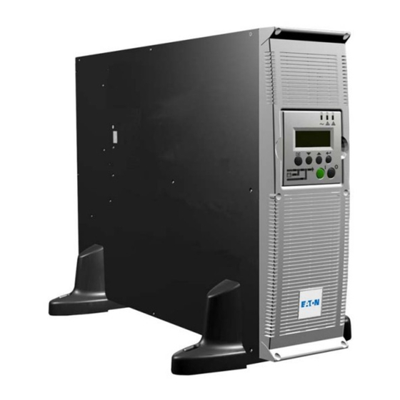
- Página 1 4000 RT 5000 RT Installation and user manual English Français Deutsch Italiano Español Nederlands Pulsar Series...
- Página 2 3400803000/AD...
-
Página 3: Pulsar Series
4000 RT 5000 RT Installation and user manual Pulsar Series... - Página 4 34008030EN/AD - Page 2...
-
Página 5: Environmental Protection
Before installing MX, please read the booklet on the required safety instructions. Then follow the indications in this manual. To discover the entire range of EATON products and the options available for the MX range, we invite you to visit our web site at www.eaton.com or contact your EATON representative. - Página 6 Introduction Pictograms Important instructions that must always be followed. Information, advice, help. Visual indication. Action. Audio signal. In the illustrations on the following pages, the symbols below are used: LED off LED on 34008030EN/AD - Page 4...
-
Página 7: Tabla De Contenido
Contents Presentation Standard positions ........................7 Tower position..........................7 Rack position..........................7 Rear panels ........................... 8 MX 4000 RT / 5000 RT ........................8 PMX EXB RT (optional battery module) ..................8 Display and control panel ......................9 Options ............................9 Rack mounting kit .......................... - Página 8 Contents Troubleshooting Troubleshooting LEDS (21) and (22) ..................28 Troubleshooting not requiring EATON after-sales support .............28 Troubleshooting requiring EATON after-sales support............29 Life Cycle Monitoring (LCM) Description ..........................30 Secure your installation power continuity..................30 Reset or disable LCM ........................30 Maintenance Hot swapping the power sub-module..................31 Hot swapping the battery sub-module ..................31...
-
Página 9: Presentation
1. Presentation 1.1 Standard positions Tower position Dimensions (H x W x D) in mm / Inches MX 4000 RT 444.5 x 131 x 700 / 17.5 x 5.16 x 27.56 MX 5000 RT 444.5 x 131 x 700 / 17.5 x 5.16 x 27.56 MX EXB RT 444.5 x 131 x 650 /... -
Página 10: Rear Panels
1. Presentation 1.2 Rear panels MX 4000 RT / 5000 RT (1) Two groups of 2 programmable (10A) outlets for connection of equipment (2) Groups of 4 (10A) outlets for connection of equipment (3) Groups of 2 (16A) outlets for connection of equipment (4) 12A thermal switch (5) 20A thermal switch... -
Página 11: Display And Control Panel
1. Presentation 1.3 Display and control panel (20) Load protected LED (21) Downgraded operation LED (22) Load not protected LED (23) Alphanumeric display (24) Escape (cancel) button (25) (26) Function buttons (scroll down / scroll up) (27) Enter (confirm) button (28) UPS OFF button (29) UPS ON button (30) Rectifier LED... - Página 12 1. Presentation ModularEasy MX ModularEasy enables parallel operation when combining two MX UPSs. Consequently you can enhance the availbility level of your equipment (N+1 redundancy). You can also double your secured power capacity according to your needs (migration, network extension...). In the unlikely event a major fault would occur, the manual maintenance bypass of MX ModularEasy would allow the UPS...
-
Página 13: Battery Extensions For Ups Backup Times Up To 80 Minutes
1. Presentation Battery extensions for UPS backup times up to 80 minutes (at full load) MX RT offers a standard backup time of 5/7 minutes at full load. To increase backup time, it is possible to connect MX EXB RT modules to the UPSs. Battery extensions for MX RT Battery Integration System The Battery Integration System is... -
Página 14: Installation
2. Installation 2.1 Unpacking and contents check (40) MX 4000 or 5000 UPS. (46) Screw driver. (41) Two sets of tower stands. (47) Solution-Pac power management suite CD-ROM. (42) RS232 communications cable (48) Network Management card (optional, or standard in NetPack version). -
Página 15: Installation In Tower Position
2. Installation 2.3 Installation in tower position Follow steps 1 to 3 to adjust the tower stands for the upright position. Always keep 150 mm free space behind the UPS rear panel. The distance between the tower stands should be 450 mm. 34008030EN/AD - Page 13... -
Página 16: Installation In Rack Position
2. Installation 2.4 Installation in rack position Adjustment of the orientation of the logo and control panel UPS module rack mounting (optional rails required) MX RT is very heavy. To ease its rack integration, we strongly recommend to remove the battery tray as shown below: 1 - Remove the 6 fixing screws to free the main front panel bezel. -
Página 17: Ups Or Battery Module Rack Mounting
Follow steps 1 to 4 for rack mounting the UPS onto the rails. The rails and the necessary mounting hardware are supplied by EATON. Note for step 1: it is possible to adjust the position of both front mounting ears. -
Página 18: Communication Ports
The output contact port is used for basic signaling or for protection of IT systems like IBM iSeries (formerly AS400) and more. The slot is compatible with any EATON communication card (check www.eaton.com web site for the complete list of compatible cards). -
Página 19: Remote Power Off Communication Port
2. Installation Remote Power Off communication port (16) (see page 8) Installation of a Remote Power Off function must be carried out in compliance with applicable regulations. In order to fully de-energize devices and MX RT with the RPO port, it is necessary: to use a two-position switch (Normally Open or Closed contact should be held more than 1 second to be taken into account). -
Página 20: Required Protective Devices And Cable Cross-Sections
2. Installation 2.6 Required protective devices and cable cross-sections Recommended upstream protection The indicated protection ensures UPS power rating Upstream circuit breaker discrimination for each output circuit 4000 RT D curve - 32A downstream of the UPS. If these recommendations are not 5000 RT D curve - 32A followed, protection discrimination is not... -
Página 21: Connection Of Input/Output Power Cables To Ups Terminals
2. Installation 2.7 Connection of input/output power cables on UPS terminals This type of connection must be carried out by qualified electrical personnel. Before carrying out any connection, check that the battery circuit breaker (19) (see page 8) and that the upstream protection device (Normal AC source) is open ("0"). -
Página 22: Connection Of Iec Cables To Output Receptacles
16 A outlet (3). To program shutdown of outlets (2) during operation on battery power and thus optimise the available backup time, the EATON communication software is required. 2 - Fit the connection securing system (44) that prevents the plugs from being pulled out accidentally. -
Página 23: Operation
3. Operation 3.1 Initial start-up It is essential to contact our Customer Service to ensure that your system is commissionned in complete safety and to benefit from the manufacturer’s guarantee. 1 - Check that the battery switch (60) (see section 2.2, page 12) on top cover is connected. -
Página 24: Operating Modes
3. Operation 3.3 Operating modes Normal mode This is the standard operating mode, set by default in the factory. Under normal condition (Normal AC source available): LED (20) is ON. LEDs (30), (32), (34) are green. The equipments are protected by the UPS. -
Página 25: Operation On Battery Power
3. Operation 3.4 Operation on battery power When the Normal AC source is not available, the load continues to be protected by the UPS. Power is supplied by the battery. Transfer to battery power LEDs (20), (21) are ON. LEDs (31), (32), (34) are green. The audio alarm beeps every 10 seconds. -
Página 26: Ups Shutdown
3. Operation 3.6 UPS shutdown 1 - Press the "0" button (28) more than 3s. The buzzer beeps once, and the load is no longer protected by the UPS. It is powered via the Normal AC source. If the UPS is set in frequency converter mode, the equipments will not be powered. -
Página 27: Access To Measurements And Personalisation Data
4. Access to measurements and personalisation data 4.1 Display organisation Measurements UPS Set-up Maintenance 4.2 Access to measurements Press the scroll button (24) (see section 1.3, page 9) to access measurements for voltage, current, frequency, power output and battery capacity. 4.3 Access to UPS set-up and maintenance using the control panel (23) Press the scroll button (25) a number of times to point the UPS set-up or... -
Página 28: Output Settings
4. Access to measurements and personalisation data 4.4 UPS set-up Local settings Function Factory setting Options English French, German, Italian, Portuguese, Spanish Language Date / Time Format International US (MM-DD-YYYY/HH:MM AM/PM) (DD-MM-YYYY/HH :MM) Date / Time Change GMT + 1 MM-DD-YYYY/HH :MM adjustable (Continental Europe) Audible Alarm... -
Página 29: Battery Settings
User Batt Settings UPS reads number of From 0 to 40 Ah 5 Ah increment battery modules connected Protection against deep discharge. Deep Disch Protect If disable, EATON warranty will be void 4.5 Maintenance Function Sub-Function Option / Display Comments Model... -
Página 30: Troubleshooting
(25) to get access to further details. In case of "LCM WARNING", refer to LCM section (see section 6). 5.2 Troubleshooting not requiring EATON after-sales support Press the "Enter" button (27) to display the details below : Displayed details Signification... -
Página 31: Troubleshooting Requiring Eaton After-Sales Support
5. Troubleshooting 5.3 Troubleshooting requiring EATON after-sales support Note: In case of multiple fault, press the "Enter" button (27) and the scroll button (25) to get access to further details. Display Signification Correction POWER MODULE FAULT Internal power sub-module fault detected. -
Página 32: Life Cycle Monitoring (Lcm)
: LCM warning details Signification BATTERY CHECK RECOMMENDED Battery is approaching its reliability end of life. Risk to reduce CONTACT EATON AT dramatically backup time www.eaton.com Reset or disable LCM In case of any LCM messages displayed:... -
Página 33: Maintenance
7. Maintenance 7.1 Hot swapping the power sub-module This operation must be carried out by qualified electrical personnel only. This operation can be performed without interrupting the equipments. Disconnecting the power sub-module : 1 - Remove the 6 fixing screws to free the main front panel bezel. -
Página 34: Maintenance On A Ups Equipped With The Modulareasy Mx Module
Reconnecting the battery sub-module : Carry out the above instructions in reverse order. To ensure safety and high performance, use only batteries supplied by EATON. 7.3 Maintenance on a UPS equipped with the ModularEasy MX module Before any action on the manual bypass (61) located on the ModularEasy module front panel, always check that the inverter is stopped (press the "0"... -
Página 35: Training Centre
7. Maintenance 7.4 Training centre To fully master operation of your EATON product and carry out level 1 servicing, see our complete range of technical training courses, available in both French and English. For further information, please visit our website: www.eaton.com... -
Página 36: Appendices
8. Appendices 8.1 Technical specifications MX 4000 MX 5000 MX EXB Output power 4000 VA / 5000 VA 3600 W 4500 W Electrical supply network Rated input voltage Single phase 230 V Input voltage range 120 / 156 V to 280 V Frequency 50/60 Hz (autoselection) Power factor... -
Página 37: Glossary
Personalisation It is possible to modify certain UPS parameters set in the factory. Certain UPS functions can also be modified by the EATON power management products to better suit user needs. These outlets can be automatically shut down during operation on battery power... - Página 38 34008030EN/AD...
-
Página 39: Pulsar Series
4000 RT 5000 RT Manuel d’installation et d’utilisation Pulsar Series... - Página 40 34008030FR/AD - Page 2...
-
Página 41: Respect De L'environnement
Avant l’installation de MX, lire le livret qui présente les consignes de sécurité à respecter. Suivre ensuite les instructions du présent manuel. Nous vous invitons à découvrir l'offre de EATON ainsi que les options de la gamme MX en visitant notre site WEB : www.eaton.com, ou en contactant votre représentant EATON. -
Página 42: Pictogrammes Utilisés
Introduction Pictogrammes utilisés Consignes à suivre impérativement. Informations, conseils, aide. Indication visuelle à observer. Action à réaliser. Signalisation sonore. Les conventions adoptées pour représenter les voyants dans les illustrations sont les suivantes : Voyant éteint. Voyant allumé. 34008030FR/AD - Page 4... - Página 43 Sommaire Présentation Positions standards ........................7 Position tour ........................... 7 Position rack ........................... 7 Faces arrières ..........................8 MX 4000 RT / 5000 RT ........................8 MX EXB RT (module batterie optionnel) ..................8 Panneau d'affichage et de commande ..................9 Options ............................
- Página 44 Sommaire Dépannage Dépannage à l’aide des voyants (21) et (22) ................28 Dépannage sans recours au service après vente EATON............28 Dépannage avec recours au service après vente EATON............29 Life Cycle Monitoring (LCM) Description ..........................30 Sécuriser la continuité de fonctionnement de l’installation ............30 Mise hors service du LCM ......................30...
-
Página 45: Présentation
1. Presentation 1.1Positions standards Position tour Dimensions (H x L x P) en mm MX 4000 RT 444.5 x 131 x 700 MX 5000 RT 444.5 x 131 x 700 MX EXB RT 444.5 x 131 x 650 Poids en kg MX 4000 RT MX 5000 RT MX EXB RT... -
Página 46: Faces Arrières
1. Présentation 1.2 Faces arrières MX 4000 RT / 5000 RT (1) 2 groupes de 2 prises programmables SWITCHED SWITCHED GROUP 2 GROUP 1 pour le raccordement des équipements (2) Groupe de 4 prises pour le raccordement des équipements (3) 2 prise 16A pour le raccordement des équipements (4) Disjoncteur thermique 12A (5) Disjoncteur thermique 20A... -
Página 47: Panneau D'affichage Et De Commande
1. Presentation 1.3 Panneau d'affichage et de commande (20) Voyant équipements protégés (21) Voyant de fonctionnement dégradé (22) Voyant équipements non protégés (23) Affichage alphanumérique (24) Bouton d’abandon, de retour (25) (26) Boutons de fonction (défilement haut / défilement bas) (27) Bouton de validation (28) Bouton d’arrêt de l’ASI (29) Bouton de mise en marche de l’ASI... -
Página 48: Modulareasy Mx
1. Présentation ModularEasy MX MX ModularEasy permet d'associer deux ASI MX pour les faire fonctionner en parallèle. Vous pouvez ainsi augmenter le niveau de disponibilité de vos équipements raccordés (redondance N+1). Vous pouvez aussi doubler la puissance de votre réseau secours en fonction de vos besoins (migration, augmentation du nombre de postes connectés...). -
Página 49: Système D'assemblage Des Modules Batterie Sur Chariot
1. Présentation Extensions batterie pour autonomies batterie de 80 minutes maximum (à pleine puissance) MX RT offre une autonomie standard de 5/7 minutes à puissance nominale. Pour augmenter l’autonomie, il est possible de raccorder des modules supplémentaires MX EXB RT à l’ASI. EXtensions batterie pour MX RT Système d’assemblage des modules batterie sur chariot Ce système permet d’assembler, dans le... -
Página 50: Installation
2. Installation 2.1 Déballage et vérification du contenu (40) ASI MX 4000 ou MX 5000. (46) Tournevis. (41) Pieds de maintien. (47) CD-ROM contenant la suite logicielle Solution-Pac. (42) Câble de communication RS232. (48) Carte de communication «Network Management card» (option, ou standard dans la version NetPack). (43) Documentation. -
Página 51: Installation En Position Tour
2. Installation 2.3 Installation en position tour Suivre les étapes 1 à 3 pour ajuster les pieds de maintien en vue de maintenir l’ASI en position verticale. Veiller à toujours conserver un espace libre de 150 mm à l’arrière de l’ASI. L’écartement entre les deux paires de pieds de maintien doit être de 450 mm. -
Página 52: Installation En Position Rack
2. Installation 2.4 Installation en position rack Modification de l’orientation du logo et du panneau de commande Montage en rack du module ASI (rails optionnels requis) MX RT est très lourd. Pour une manipulation aisée lors du montage, il est recommandé d’extraire les éléments batterie du module comme indiqué... -
Página 53: Montage En Rack Du Module De Puissance Ou Batterie
Suivre les étapes 1 à 4 pour le montage du module sur ses rails. Les rails et le nécessaire de montage sont fournis par EATON. Note pour l’étape 1: il est possible d’ajuster la position des équerres de fixation frontales. -
Página 54: Ports De Communication
MX RT fournit trois modes de communication qui peuvent être utilisés simultanément : 2 ports de communication, RS 232 et USB qui utilisent le protocole EATON SHUT compatible avec les logiciels de supervision et de protection inclus dans le CD-Rom Solution Pac. Il est à noter que les deux ports ne doivent pas être utilisés simultanément. -
Página 55: Raccordement De L'arrêt D'urgence
2. Installation Raccordement de l’arrêt d’urgence (16) (voir son implantation page 8) L'installation d'un arrêt d'urgence doit être réalisée conformément aux normes en vigueur. Afin d'obtenir une mise hors tension totale de l'installation et de MX RT par l'action d'un arrêt d'urgence, il est nécessaire : D'utiliser un bouton à... -
Página 56: Organes De Protection Et Sections De Câbles Recommandés
2. Installation 2.6 Organes de protection et sections de câbles recommandés Protection amont recommandée Les protections indiquées assurent la Puissance nominale de l’ASI Disjoncteur amont discrimination entre chaque départ aval 4000 RT D courbe - 32A de l’ASI. Si ces recommandations ne sont pas 5000 RT D courbe - 32A respectées, la sélectivité... -
Página 57: Raccordement Des Câbles De Puissance D'entrée Et Sortie
2. Installation 2.7 Raccordement des câbles de puissance d’entrée et sortie Ces raccordements doivent être réalisés par du personnel qualifié. Avant d’effectuer les raccordements, vérifier que le disjoncteur batterie (19) (voir son implantation page 8) et le disjoncteur de protection amont (réseau AC Normal) sont en position ouverts ("0"). Utiliser les embouts de câblage fournis. -
Página 58: Raccordement Des Câbles De Type Iec Sur Les Prises De Sortie
Pour programmer l’arrêt des prises (2) lors d’un fonctionnement sur batterie et optimiser ainsi l’autonomie batterie, il est nécessaire de recourir au logiciel de communication EATON. 2 - Pour prévenir tout arrachement accidentel des câbles, les bloquer à l’aide du système de verrouillage (44). -
Página 59: Utilisation
3. Utilisation 3.1 Mise en service initiale Il est essentiel de contacter notre service après vente pour s’assurer que l’ASI fonctionne en toute sécurité et bénéficier de la garantie constructeur. 1 - Vérifier que le connecteur batterie (60) (voir paragraphe 2.2, page 12) sur le dessus de l’appareil est fermé... -
Página 60: Modes De Fonctionnement
3. Utilisation 3.3 Modes de fonctionnement Mode de fonctionnement normal C’est le mode de fonctionnement standard. Dans des conditions normales (réseau AC Normal présent) : Le voyant (20) est allumé. Les voyants (30), (32), (34) sont allumés en vert. Les équipements sont protégés par l’ASI. Mode ECO Le principal avantage du mode ECO (voir glossaire) est la réduction de la... -
Página 61: Fonctionnement Sur Batterie
3. Utilisation 3.4 Fonctionnement sur batterie Quand le réseau AC Normal est absent, les équipements raccordés continuent d’être alimentés par l’ASI. L’énergie est fournie par la batterie. Passage sur batterie Les voyants (20), (21) sont allumés. Les voyants (31), (32), (34) sont allumés en vert. -
Página 62: Arrêt De L'asi
3. Utilisation 3.6 Arrêt de l’ASI 1 - Presser le bouton "0" (28) plus de 3 secondes. Le buzzer émet un seul bip, et les équipements raccordés ne sont plus protégés par l’ASI. Ils sont alimentés par le réseau AC Normal. Si l’ASI est paramétrée en mode convertisseur de fréquence, les équipements ne sont plus alimentés. -
Página 63: Accès Aux Mesures Et Personnalisation
4. Accès aux mesures et personnalisation 4.1 Synoptique de l’afficheur ETATS ET ALARMES MESURES MESURES ENTREE ASI MESURES SORTIE ASI MESURES BATTERIE CONFIGURATION ASI MAINTENANCE REGLAGES LOCAUX MODELE REGLAGES DE SORTIE HISTORIQUE DEFAUTS REGLAGES ON/OFF TEST BATT MANUEL REGLAGES BATTERIE TEST LEDS &... - Página 64 4. Accès aux mesures et personnalisation 4.4 Configuration de l’ASI REGLAGES LOCAUX Fonction Personnalisation usine Autres choix ANGLAIS FRANCAIS, ALLEMAND, ITALIEN, ESPAGNOL, PORTUGAIS LANGUE FORMAT DATE/HEURE INTERNATIONAL US (MM-JJ-AAAA/HH:MM AM/PM) (JJ-MM-AAAA/HH :MM) MODIF DATE/HEURE GMT + 1 MM-JJ-AAAA/HH :MM réglables (Continental Europe) ALARME SONORE REGLAGES DE SORTIE...
-
Página 65: Maintenance
Détection automatique De 0 à 40 Ah Par pas de 5 Ah BATT du nombre de modules batterie PROTECT DECHA PROF Si inactive, perte de la garantie EATON. 4.5 Maintenance Fonction Sous fonction Options / Affichage Commentaires MODULE PUISSANCE SN: xxxxxxxxx Numéro de série... -
Página 66: Dépannage
(27) et le bouton de fonction (25) pour accéder aux détails. En cas d’affichage "ALERTE LCM", se référer au chapitre LCM (chapitre 6). 5.2 Dépannage sans recours au service après vente EATON CHARGE PROTEGEE x.xkVA / xxx% CHARGE DEF ENVIRONNEMENT... -
Página 67: Dépannage Avec Recours Au Service Après Vente Eaton
5. Dépannage 5.3 Dépannage avec recours au service après vente EATON Nota : en cas de défauts multiples, presser le bouton de validation (27) et le bouton de fonction (25) pour accéder aux détails. CHARGE PROTEGEE x.xkVA / xxx% CHARGE... -
Página 68: Life Cycle Monitoring (Lcm)
Détails des alarmes LCM Signification CONTROLE BATTERIES RECOMMANDE La batterie est proche de sa fin de vie. L’autonomie batterie risque de CONTACTER EATON : diminuer fortement. www.eaton.com Mise hors service du LCM Dans le cas d’affichage de messages LCM : pour un acquitement temporaire : presser le bouton d’abandon (24) plus de 3... -
Página 69: Maintenance
7. Maintenance 7.1 Remplacement du sous-module de puissance Cette opération ne doit être exécutée que par du personnel qualifié. Cette opération peut être exécutée sans interrompre l’alimentation des équipements raccordés. Déconnexion du sous-module de puissance : 1 - Enlever le panneau frontal (fixé par 6 vis). -
Página 70: Maintenance D'une Asi Équipée D'un Module Modulareasy Mx
Remise en place du sous-module batterie : Suivre les instructions ci-dessus dans l’ordre inverse. Pour garantir sécurité et bonnes performances, utiliser uniquement des batteries fournies par EATON. 7.3 Maintenance d’une ASI équipée d’un module ModularEasy MX Avant toute manoeuvre du commutateur manuel de By-pass (61) situé en face avant du module ModularEasy, vérifier que l’ASI est à... -
Página 71: Centre De Formation
7. Maintenance 7.4 Centre de formation Pour maîtriser l'exploitation de votre appareil EATON et intervenir au premier niveau, nous mettons à votre disposition un programme complet de formations techniques en langues anglaise et française. Pour plus d'informations, consulter notre site internet : www.eaton.com... -
Página 72: Annexes
8. Annexes 8.1 Spécifications techniques MX 4000 MX 5000 MX EXB Puissance de sortie 4000 VA / 5000 VA 3600 W 4500 W Réseau électrique d’alimentation Tension d’entrée nominale Monophasée 230 V Plage de tension d’entrée 120 / 156 V à 280 V Fréquence 50/60 Hz (auto-sélection) Facteur de puissance... -
Página 73: Glossaire
8. Annexes 8.2 Glossaire AC By-pass Voie dérivée du réseau électrique d’alimentation, commandée par l’ASI et permettant une alimentation directe des équipements raccordés par le réseau électrique en cas de surcharge ou de dysfonctionnement de l’onduleur. Alimentation Sans Interruptions Autonomie Temps pendant lequel les équipements raccordés sont alimentés par l’ASI fonctionnant sur batterie. - Página 74 34008030FR/AD...
-
Página 75: Pulsar Series
4000 RT 5000 RT Installations- und Bedienungsanleitung Pulsar Series... - Página 76 34008030DE/AD - Page 2...
- Página 77 Einführung Wir danken Ihnen, dass Sie sich für ein Produkt von EATON zum Schutz Ihrer Geräte entschieden haben. Die Baureihe MX wurde mit größter Sorgfalt entwickelt. Um die Leistungen Ihrer USV (Unterbrechungsfreien Strom Versorgung) optimal nutzen zu können, empfehlen wir Ihnen, sich ein wenig Zeit zu nehmen und das vorliegende Handbuch aufmerksam zu lesen.
-
Página 78: Bedeutung Der Piktogramme
Einführung Bedeutung der Piktogramme WICHTIG! Hinweise unbedingt befolgen. Informationen, Ratschläge, Hilfe. Optische Anzeige. Maßnahmen, Handlungen. Akustischer Alarm. In den Abbildungen der nachfolgenden Seiten sind die LED-Anzeigen durch folgende Symbole dargestellt: LED aus. LED an. 34008030DE/AD - Page 4... - Página 79 Inhalt Ansichten und Beschreibung Aufstellungsarten......................... 7 Tower-Modell..........................7 Rack-Modell ........................... 7 Rückansicht ..........................8 MX 4000 RT / 5000 RT ........................8 MX EXB RT (optional erhältliches Batteriemodul) ................8 Anzeige- und Bedienfeld ......................9 Optionen ............................9 Montagematerial für Rackeinbau ....................9 ModularEasy MX...........................10 Batterieerweiterungsmodule für Autonomiezeiten bis zu 80 Minuten .........11 Rahmengestell für den Einbau mehrerer Batteriemodule ............11...
- Página 80 Inhalt Fehlerbehebung Fehlerbehebung mit Hilfe der Leuchtdioden (21) und (22) .............28 Fehlerbehebung ohne Inanspruchnahme des EATON-Kundendienstes ........28 Fehlerbehebung mit Inanspruchnahme des EATON-Kundendienstes........29 Life Cycle Monitoring (LCM) Beschreibung ..........................30 Sicherung des unterbrechungsfreien Betriebs der Anlage ............30 Abschalten des LCM ........................30 Wartung und Service Austausch des Leistungsmoduls ....................31...
-
Página 81: Ansichten Und Beschreibung
1. Ansichten und Beschreibung 1.1 Aufstellungsarten Tower-Modell Abmessungen (H x B x T) in mm MX 4000 RT 444,5 x 131 x 700 MX 5000 RT 444,5 x 131 x 700 MX EXB RT 444,5 x 131 x 650 Gewicht in kg MX 4000 RT MX 5000 RT MX EXB RT... -
Página 82: Rückansicht
1. Ansichten und Beschreibung 1.2 Rückansicht MX 4000 RT / 5000 RT (1) 2 Gruppen mit je 2 fernsteuerbaren Steckdosen für den Anschluss der Verbraucher (2) Gruppe mit 4 Steckdosen für den Anschluss der Verbraucher (3) 2 Steckdose 16 A für den Anschluss der Verbraucher (4) Thermischer Schutzschalter 12 A (5) Thermischer Schutzschalter 20 A... -
Página 83: Anzeige- Und Bedienfeld
1. Ansichten und Beschreibung 1.3 Anzeige- und Bedienfeld (20) LED: Verbraucher geschützt (21) LED: Leichte Störung (22) LED: Verbraucher nicht geschützt (23) Alphanumerische Anzeige (24) Abbruch-/Rücksprungtaste (25) (26) Funktionstasten (aufwärts/ abwärts) (27) Bestätigungstaste (28) Taster USV AUS (29) Taster USV EIN (30) LED: Gleichrichter (31) LED: Batterie (32) LED: Wechselrichter... -
Página 84: Modulareasy Mx
1. Ansichten und Beschreibung ModularEasy MX Mit dem MX ModularEasy können zwei MX parallel geschaltet werden. Sie können so die Verfügbarkeit Ihrer angeschlossenen Verbraucher erhöhen (Redundanz N+1). Außerdem können Sie die Leistung Ihres Notstromnetzes je nach Bedarf verdoppeln (Systemumstellung, Anzahl der angeschlossenen Systeme...). -
Página 85: Batterieerweiterungsmodule Für Autonomiezeiten Bis Zu 80 Minuten
1. Ansichten und Beschreibung Batterieerweiterungsmodule für Autonomiezeiten bis zu 80 Minuten (bei Volllast) MX RT bietet standardmäßig eine Autonomiezeit von 5/7 Minuten bei Nennleistung. Zur Erhöhung der Autonomiezeit können zusätzliche MX EXB RT-Erweiterungsmodule an die USV angeschlossen werden. Batterie-Erweiterungsmodule für MX RT Rahmengestell für den Einbau mehrerer Batteriemodule Dieses Rahmengestell erlaubt die Zusammenfassung von bis zu 9 Modulen,... -
Página 86: Aufstellung Und Installation
2. Aufstellung und Installation 2.1 Entfernen der Verpackung und Überprüfung des Lieferumfangs (40) USV-Modul MX 4000 oder MX 5000. (46) Schraubendreher. (41) Aufstellfüße. (47) CD-ROM mit der Software Solution-Pac. (42) RS232-Kommunikationskabel. (48) Netzwerkkarte „Network Management Card“ (Standard bei NetPack, sonst Option). (43) Unterlagen. -
Página 87: Aufstellung Des Tower-Modells
2. Aufstellung und Installation 2.3 Aufstellung des Tower-Modells Um die Aufstellfüße für eine vertikale Ausrichtung der USV einzustellen, befolgen Sie die Schritte 1 bis 3. Achten Sie darauf, an der Rückseite der USV einen Abstand von 150 mm zu lassen. Der Abstand zwischen den zwei Paar Aufstellfüßen muss 450 mm betragen. -
Página 88: Aufstellung Des Rack-Modells
2. Aufstellung und Installation 2.4 Aufstellung des Rack-Modells Drehen des Firmenschilds und des Bedien- und Anzeigefelds Einbau des USV-Moduls (optional erhältliche Montageschienen erforderlich) MX RT ist sehr schwer. Zur leichteren Handhabung empfiehlt es sich, die Batterieelemente wie nachstehend abgebildet für die Dauer der Montage herauszunehmen: 1 - Die 6 Befestigungsschrauben herausdrehen, um die Frontabdeckung zu entfernen. -
Página 89: Einbau Des Leistungs- Oder Batteriemoduls
Die USV und das Batteriemodul müssen in einem belüfteten Raum installiert werden. Zur Befestigung des Moduls auf den Montageschienen Schritte 1 bis 4 befolgen. Die Schienen und das benötigte Montagematerial werden von EATON geliefert. Hinweis zu Schritt 1: Die vorderen Befestigungswinkel können in mehreren Positionen montiert werden. -
Página 90: Schnittstellen
2 Schnittstellen stehen für eine Kommunikation über eine RS232- oder USB-Verbindung mit eigenem SHUT- Protokoll von EATON zur Verfügung. Dieses Protokoll ist mit der auf CD-ROM mitgelieferten USV-Software Solution Pac kompatibel. Bitte beachten Sie, dass die beiden Schnittstellen nicht gleichzeitig benutzt werden dürfen. -
Página 91: Anschluss Der Not-Aus-Verbindung
2. Aufstellung und Installation Anschluss der Not-AUS-Verbindung (16) (Anordnung siehe Seite 8) Der Anschluss einer Not-AUS-Verbindung muss übereinstimmend mit den geltenden Normen ausgeführt werden. Um eine vollständige Trennung sämtlicher an die MX RT angeschlossenen Spannungsquellen im Falle eines Not- Aus-Befehls zu gewährleisten, ist es erforderlich: Einen Taster mit Rastfunktion zu benutzen (Der S- oder Ö-Kontakt muss mehr als eine Sekunde gehalten werden, damit der Befehl ausgeführt wird), An den Taster mit Rastfunktion eine einzige Vorrichtung anzuschließen, die das Öffnen des (der) vor... -
Página 92: Empfohlene Schutzorgane Und Leiterquerschnitte
2. Aufstellung und Installation 2.6 Empfohlene Schutzorgane und Leiterquerschnitte Empfohlene netzseitige Absicherung Die angegebenen Absicherungen USV-Nennleistung Sicherungsautomat gewährleisten die Selektivität jedes USV- 4000 RT D-Kurve - 32 A Abgangs. Bei Nichteinhaltung dieser Empfehlungen 5000 RT D-Kurve - 32 A ist der Selektivschutz nicht gewährleistet, und es kann zur Unterbrechung der Stromversorgung der angeschlossenen Verbraucher kommen. -
Página 93: Anschluss Der Leistungskabel Am Usv-Eingang Und -Ausgang
2. Aufstellung und Installation 2.7 Anschluss der Leistungskabel am USV-Eingang und -Ausgang Die Anschlüsse müssen durch qualifiziertes Fachpersonal ausgeführt werden. Vor Ausführung der Anschlüsse ist sicherzustellen, dass der Batterie-Leistungsschalter (19) (Anordnung siehe Seite 8) und der netzseitige Sicherungsautomat (Netz AC Normal) ausgeschaltet sind (Stellung „0“). Mitgelieferte Kabelendhülsen verwenden. -
Página 94: Anschluss Der Iec-Kabel An Die Ausgangssteckdosen
Um die Abschaltung der Steckdosen (2) bei Batteriebetrieb zu parametrieren und somit die Autonomiezeit zu optimieren, benötigt man die Kommunikationssoftware EATON. 2 - Um ein unbeabsichtigtes Abziehen der Kabel zu vermeiden, werden diese mit einem Sicherheitsbügel (44) befestigt. 34008030DE/AD - Page 20... -
Página 95: Betriebszustände
3. Betriebszustände 3.1 Erstinbetriebnahme Um den sicheren Betrieb der USV zu überprüfen und die Herstellergarantie in Anspruch zu nehmen, wenden Sie sich bitte an unseren Kundendienst. 1 - Prüfen, ob der Batterieanschluss (60) (siehe Abschnitt 2.2, Seite 12) auf dem Gerät geschlossen ist (Anzeige „connected“... -
Página 96: Betriebsarten
3. Betriebszustände 3.3 Betriebsarten Normalbetrieb Dies ist die Standardbetriebsart. Normale Bedingungen (Einspeisenetz AC Normal vorhanden): LED (20) leuchtet. Die Leuchtdioden (30), (32) und (34) leuchten grün. Die angeschlossenen Verbraucher sind durch die USV geschützt. ECO-Modus Ein wesentlicher Vorteil des ECO-Modus (siehe Fachbegriffe) ist die Verringerung des Energieverbrauchs. -
Página 97: Batteriebetrieb
3. Betriebszustände 3.4 Batteriebetrieb Bei Ausfall von Netz AC Normal bleiben die angeschlossenen Verbraucher weiterhin durch die USV geschützt. Die erforderliche Versorgungsenergie wird von der Batterie geliefert. Umschaltung auf Batteriebetrieb Die Leuchtdioden (20) und (21) leuchten. Die Leuchtdioden (31), (32) und (34) leuchten grün. -
Página 98: Abschaltung Der Usv
3. Betriebszustände 3.6 Abschaltung der USV 1- Taste „0“ (28) länger als 3 Sekunden gedrückt halten. Der Summer ertönt ein einziges Mal und die angeschlossenen Verbraucher sind nicht mehr durch die USV geschützt. Die Versorgung erfolgt über das Netz AC Normal. -
Página 99: Zugriff Auf Die Messwerte Und Kundenspezifische Anpassung
4. Zugriff auf die Messwerte und kundenspezifische Anpassung 4.1 Übersicht Messwerte USV Setup Wartung 4.2 Zugriff auf die Messwerte Um die Messwerte für Spannung, Strom, Frequenz, Ausgangsleistung und Autonomiezeit der Batterie aufzurufen, Funktionstaste (24) drücken (siehe Abschnitt 1.3 auf Seite 9). 4.3 Kundenspezifische Anpassung und Wartung über das Bedienfeld (23) Mehrmals die Funktionstaste (25) drücken, bis das Menü... -
Página 100: Konfiguration Der Usv
4. Zugriff auf die Messwerte und kundenspezifische Anpassung 4.4 Konfiguration der USV EINSTELLUNGEN Funktion Werksseitige Optionen Einstellung SPRACHE ENGLISCH FRANZÖSISCH, DEUTSCH, ITALIENISCH, SPANISCH, PORTUGIESISCH DATUM/ZEITFORMAT INTERNATIONAL US (MM-TT-JJJJ/HH:MM AM/PM) (TT-MM-JJJJ/HH:MM) DATUM/ZEIT ÄNDERN GMT + 1 MM-TT-JJJJ/HH:MM einstellbar (Kontinentaleuropa) AKUST. ALARM NEIN AUSG.-PARAMETER Funktion... -
Página 101: Wartung
BAT. -PARAMETER Automatische 0 bis 40 Ah Einstellbar in Schritten von 5 Ah Erkennung der Anzahl der Batteriemodule TIEFENTLADESCHUTZ NEIN Bei Einstellung „inaktiv“ Verlust der EATON Garantie. 4.5 Wartung Funktion Unterfunktion Optionen / Anzeige Anmerkungen MODELL POWER MODUL SN: xxxxxxxxx... -
Página 102: Fehlerbehebung
Anzeige erscheint, Bestätigungstaste (27) und Funktionstaste (25) drücken, um Einzelheiten abzufragen. Wenn „LCM-WARNUNG“ in der Anzeige erscheint, siehe Kapitel LCM (Kapitel 6). 5.2 Fehlerbehebung ohne Inanspruchnahme des EATON-Kundendienstes Bestätigungstaste (27) drücken, um folgende Informationen im Display aufzurufen: Fehleranzeige Fehlerursache Fehlerbehebung... -
Página 103: Fehlerbehebung Mit Inanspruchnahme Des Eaton-Kundendienstes
5. Fehlerbehebung 5.3 Fehlerbehebung mit Inanspruchnahme des EATON-Kundendienstes Hinweis: Bei Mehrfachfehlern Bestätigungstaste (27) und Funktionstaste (25) drücken, um Einzelheiten abzufragen. Fehleranzeige Fehlerursache Fehlerbehebung LEISTUNGSMODUL Leistungsmodulstörung Kundendienst benachrichtigen. FEHLER Taste (27) drücken, um Einzelheiten Anweisungen für den Austausch des abzufragen. Leistungsmoduls befolgen (siehe Abschnitt 7.1) -
Página 104: Life Cycle Monitoring (Lcm)
Die Lebensdauer der Batterie ist fast abgelaufen. Es besteht die Gefahr, ERFORDERLICH dass die Autonomiezeit der Batterie stark abnimmt. KONTAKTIEREN SIE www.eaton.com Abschalten des LCM Bei folgenden LCM-Meldungen: für eine zeitweilige Quittierung: Abbruchtaste (24) auf der Bildschirmseite „Status und Alarme“, länger als 3... -
Página 105: Wartung Und Service
7. Wartung und Service 7.1 Austausch des Leistungsmoduls Dieser Vorgang muss von einer qualifizierten Fachkraft durchgeführt werden. Der Austausch kann ohne Unterbrechung der Verbraucherversorgung durchgeführt werden. Lösen der Verbindungen: 1 - Frontabdeckung abnehmen (befestigt mit 6 Schrauben). 2 - Die Frontplatte auf die USV legen. 3 - Die 4 Befestigungsschrauben auf der linken Seite entfernen, um das Leistungsmodul aus seiner Befestigung zu... - Página 106 7. Wartung und Service Wiedereinbau des Batteriemoduls: Oben beschriebenen Vorgang in umgekehrter Reihenfolge ausführen. Um die Sicherheit und Leistungsfähigkeit zu gewährleisten, sind ausschließlich von EATON gelieferte Batterien einzusetzen. 7.3 Wartung einer mit dem ModularEasy MX-Modul ausgestatteten USV Vor Betätigung des an der Frontseite des ModularEasy-Moduls befindlichen Handumgehungsschalters (61) prüfen, ob die USV ausgeschaltet ist (Taste „0“...
-
Página 107: Schulungszentrum
7. Wartung und Service 7.4 Schulungszentrum Um Ihnen eine optimale Nutzung der Anlagen sowie eine umfassende Fehleranalyse und -behebung zu ermöglichen, bietet EATON umfangreiche Kundenschulungen in englischer und französischer Sprache an. For further information, please visit our website: www.eaton.com 34008030DE/AD - Page 33... -
Página 108: Anhang
8. Anhang 8.1 Technische Spezifikationen MX 4000 MX 5000 MX EXB Ausgangsleistung 4000 VA / 5000 VA 3600 W 4500 W Eingangsnetz Nennspannung Einphasig 230 V Spannungsbereich 120 / 156 V bis 280 V Frequenz 50/60 Hz (autom. Wahl) Leistungsfaktor >... -
Página 109: Fachbegriffe
8. Anhang 8.2 Fachbegriffe AC Bypass Durch die USV gesteuerte Umgehung des Einspeisenetzes, die bei Überlast oder einer Funktionsstörung des Wechselrichters eine direkte Versorgung der angeschlossenen Verbraucher aus dem Stromnetz ermöglicht. Autonomiezeit Zeitdauer, während der die Versorgung der Verbraucher durch die Batterie der USV erfolgt. ECO-Modus Betriebsart zur direkten Verbraucherversorgung über das Netz, wenn dessen Kennwerte innerhalb der kundenspezifischen Toleranzgrenzen liegen. - Página 110 34008030DE/AD...
-
Página 111: Pulsar Series
4000 RT 5000 RT Manuale di installazione e di utilizzazione Pulsar Series... - Página 112 34008030IT/AD - Page 2...
-
Página 113: Tutela Dell'ambiente
Prima di installare MX, leggere attentamente il libretto contenente le norme di sicurezza da rispettare. Leggere quindi le istruzioni del presente manuale. Vi invitiamo a scoprire l’offerta della EATON, come pure le opzioni della gamma MX visitando il nostro sito WEB www.eaton.com o contattando il vostro rappresentante EATON. - Página 114 Introduzione Pittogrammi utilizzati Istruzioni da seguire tassativamente Informazioni, consigli, guida. Indicazione visiva da osservare. Azione da eseguire. Segnalazione acustica. Le convenzioni adottate per rappresentare le spie all’interno delle illustrazioni sono le seguenti: Spia spenta. Spia accesa. 34008030IT/AD - Page 4...
- Página 115 Sommario Presentazione Posizioni standard........................7 Posizione tower..........................7 Posizione slot ..........................7 Vista posteriore ..........................8 MX 4000 RT / 5000 RT ........................8 MX EXB RT (modulo batteria opzionale) ..................8 Pannello di visualizzazione e di comando ................. 9 Opzioni............................
- Página 116 Riparazione dei guasti Riparazione dei guasti tramite spie (21) e (22) ................28 Riparazione dei guasti senza ricorso all’assistenza post-vendita EATON......28 Riparazione dei guasti con ricorso all’assistenza post-vendita EATON ........29 Life Cycle Monitoring (LCM) Descrizione..........................30 Sicurezza del funzionamento continuo dell’installazione ..............30 Fuori servizio dell’LCM .........................30...
-
Página 117: Presentazione
1. Presentazione 1.1 Posizioni standard Posizione tower Dimensioni (A x L x P) in mm MX 4000 RT 444,5 x 131 x 700 MX 5000 RT 444,5 x 131 x 700 MX EXB RT 444,5 x 131 x 650 Peso in kg MX 4000 RT MX 5000 RT MX EXB RT... -
Página 118: Vista Posteriore
1. Presentazione 1.2 Vista posteriore MX 4000 RT / 5000 RT (1) 2 gruppi da 2 prese programmabili per SWITCHED SWITCHED GROUP 2 GROUP 1 il raccordo diretto degli impianti (2) Gruppo di 4 prese per il raccordo diretto degli impianti (3) 2 presa 16A per il raccordo diretto degli impianti (4) Interruttore termico 12A... -
Página 119: Pannello Di Visualizzazione E Di Comando
1. Presentazione 1.3 Pannello di visualizzazione e di comando (20) Spia impianti protetti (21) Spia di funzionamento deteriorato (22) Spia impianti non protetti (23) Display alfanumerico (24) Tasto in uscita, indietro (25) (26) Tasti funzione (scorrimento su/ giù) (27) Tasto di conferma (28) Tasto di arresto dell’UPS (29) Tasto di accensione dell’UPS (30) Spia raddrizzatore... -
Página 120: Modulareasy Mx
1. Presentazione ModularEasy MX MX ModularEasy consente di unire due UPS MX per il funzionamento in parallelo, aumentando così il livello di disponibilità degli impianti collegati (ridondanza N+1) e raddoppiando inoltre la potenza della rete di emergenza in funzione delle proprie esigenze (migrazione, aumento del numero di postazioni collegate, ecc.). -
Página 121: Sistema Di Assemblaggio Dei Moduli Batteria Su Carrello
1. Presentazione Estensioni batteria per autonomia fino a 80 minuti massimo (piena potenza) MX RT offre un’autonomia standard di 5/7 minuti a potenza nominale. Per aumentarla, è possibile collegare i moduli supplementari MX EXB RT all’UPS. Estensioni batteria per MX RT Sistema di assemblaggio dei moduli batteria su carrello Il sistema consente di assemblare, nel caso di UPS con autonomia della batteria... -
Página 122: Installazione
2. Installazione 2.1 Apertura dell’imballaggio e verifica del contenuto (40) UPS MX 4000 o MX 5000. (46) Cacciavite. (41) Piedini di sostegno. (47) CD-ROM contenente il pacchetto software Solution- Pac. (42) Cavo di comunicazione RS232. (48) Scheda di comunicazione«Network Management (43) Documentazione. - Página 123 2. Installazione 2.3 Installazione in posizione tower Seguire le fasi da 1 a 3 per regolare i piedini di sostegno in modo da tenere l’UPS in posizione verticale. Mantenere uno spazio libero di 150 mm dietro l’UPS. Lo scarto tra le due coppie di piedini di sostegno deve essere di 450 mm. 34008030IT/AD - Page 13...
-
Página 124: Modifica Dell'orientamento Del Logo E Del Pannello Di Comando
2. Installazione 2.4 Installazione in posizione slot Modifica dell’orientamento del logo e del pannello di comando Montaggio a slot del modulo UPS (necessarie guide opzionali) MX RT è molto pesante. Per facilitarne la movimentazione durante il montaggio, si consiglia di estrarre gli elementi batteria del modulo come indicato di seguito. - Página 125 Per il montaggio del modulo sulle guide, seguire i passaggi da 1 a 4. Le guide e il materiale necessario per il montaggio sono forniti da EATON. Nota alla fase 1: è possibile regolare la posizione delle squadre di fissaggio anteriori.
-
Página 126: Porte Di Comunicazione
MX RT fornisce tre modalità di comunicazione, utilizzabili simultaneamente: 2 porte di comunicazione, RS232 e USB che utilizzano il protocollo EATON SHUT compatibile con i software di supervisione e protezione inseriti nel CD-Rom Solution Pac. Si osservi che le due porte non devono essere utilizzate contemporaneamente. -
Página 127: Raccordo Dell'arresto Di Emergenza
2. Installazione Raccordo dell’arresto di emergenza (16) (vedere l’impianto a pagina 8) L’installazione dell’arresto di emergenza deve essere eseguita in conformità alle normative vigenti. Per la messa fuori tensione completa dell'installazione e di MX RT tramite arresto di emergenza, è necessario: utilizzare un tasto di collegamento (premere il contatto NA o NC per almeno un secondo per consentire l’esecuzione), collegare al tasto di collegamento un dispositivo unico che consenta l’apertura dell’interruttore (degli interruttori) posizionato(i) a monte... -
Página 128: Organi Di Protezione E Sezioni Di Cavo Consigliate
2. Installazione 2.6 Organi di protezione e sezioni di cavo consigliate Protezione a monte consigliata Le protezioni indicate garantiscono la Potenza nominale dell’UPS Interruttore a monte distinzione tra ogni avvio a valle dell’UPS. 4000 RT curva D - 32A In caso di mancato rispetto di tali raccomandazioni, non è... -
Página 129: Raccordo Dei Cavi Di Potenza In Entrata E Uscita
2. Installazione 2.7 Raccordo dei cavi di potenza in entrata e uscita I raccordi devono essere eseguiti da personale qualificato. Prima di procedere, accertare che l’interruttore batteria (19) (vedere l’impianto a pagina 8) e quello di protezione a monte (rete AC Normale) siano aperti ("0"). Utilizzare gli attacchi di cablaggio in dotazione. -
Página 130: Raccordo Dei Cavi Di Tipo Iec Sulle Prese In Uscita
Per programmare l’arresto delle prese (2) durante il funzionamento a batteria e ottimizzare quindi l’autonomia della batterie stessa, è necessario ricorrere al software di comunicazione EATON. 2 - Per prevenirne lo strappo accidentale, bloccare i cavi utilizzando il sistema di fissaggio (44). -
Página 131: Utilizzo
3. Utilizzo 3.1 Messa in servizio iniziale È fondamentale contattare l’assistenza post-vendita per accertare il funzionamento dell’UPS in totale sicurezza e usufruire della garanzia del costruttore. 1 - Verificare che il connettore batteria (60) (vedere paragrafo 2.2, pagina 12) sopra l’apparecchio sia chiuso (indicazione "connected"... -
Página 132: Modalità Di Funzionamento
3. Utilizzo 3.3 Modalità di funzionamento Modalità di funzionamento normale È la modalità di funzionamento standard. In condizioni normali (presenza delle rete AC Normale): La spia (20) è accesa. Le spie (30), (32) e (34) sono accese con luce verde. Gli impianti sono protetti dall’UPS. -
Página 133: Funzionamento Su Batteria
3. Utilizzo 3.4 Funzionamento su batteria In assenza di rete AC Normale, gli impianti collegati continuano a essere alimentati dall’UPS. L’energia è fornita dalla batteria. Passaggio su batteria Le spie (20) e (21) sono accese. Le spie (31), (32) e (34) sono accese con luce verde. -
Página 134: Arresto Dell'ups
3. Utilizzo 3.6 Arresto dell’UPS 1- Tenere premuto il pulsante "0" (28) per almeno 3 secondi. Il cicalino emette un solo bip e gli impianti collegati non sono più protetti dall’UPS, ma dalla rete AC Normale. Se l’UPS è parametrato in modalità convertitore di frequenza, gli impianti non sono più... -
Página 135: Accesso Alle Misure E Alla Personalizzazione
4. Accesso alle misure e alla personalizzazione 4.1 Sinottico del display STATI E ALLARMI MISURAZIONI MISURAZIONI SU ENTRATA UPS MISURIAZIONI SU USCITA UPS MISURAZIONI SULLA BATTERIA CONFIGURAZIONE UPS MANUTENZIONE REG. LOCALI MODELLO REG. USCITA STORICO EVENTI REG. ON/OFF TEST BATT MANUALE REG. -
Página 136: Configurazione Dell'ups
4. Accesso alle misure e alla personalizzazione 4.4 Configurazione dell’UPS REG. LOCALI Funzione Configurazione di Altre impostazioni fabbrica INGLESE FRANCESE, TEDESCO, ITALIANO, SPAGNOLO, PORTOGHESI LINGUA FORMATO DATO/ORA INTERNAZIONALE US (MM-GG-AAAA/HH:MM AM/PM) (GG-MM-AAAA/HH :MM) REG. ORA/GIORNO GMT + 1 Impostazione MM-GG-AAAA/HH :MM (Continental Europe) ALLARME SONORO SÌ... -
Página 137: Manutenzione
RISPARMIO ENERGIA Rilevazione automatica Da 0 a 40 Ah In step da 5 Ah del numero di moduli batteria PROT SCARICA PROF SÌ Se inattiva, perdita di garanzia EATON. 4.5 Manutenzione Funzione Sotto-funzione Opzioni/ Osservazioni Visualizzazione MODELLO MODULO POTENZA SN: xxxxxxxxx... -
Página 138: Riparazione Dei Guasti
(27) e il tasto funzione (25) per accedere ai dettagli. In caso di visualizzazione"ALLERTA LCM", fare riferimento al capitolo LCM (capitolo 5.2 Riparazione dei guasti senza ricorso all’assistenza post-vendita EATON CARICO PROTETTO x.xkVA / xxx% CARICO DIF AMBIENTE EXT UPS UNITARIO... -
Página 139: Riparazione Dei Guasti Con Ricorso All'assistenza Post-Vendita Eaton
5. Riparazione dei guasti 5.3 Riparazione dei guasti con ricorso all’assistenza post-vendita EATON Nota: se si verificano più guasti, premere il tasto di conferma (27) e il tasto funzione (25) per accedere ai dettagli. CARICO PROTETTO x.xkVA / xxx% CARICO... -
Página 140: Life Cycle Monitoring (Lcm)
Dettagli degli allarmi LCM Significato CONTROLLO BATTERIE La batteria sta per esaurirsi. L’autonomia rischia di ridursi notevolmente. RACCOMANDATO CONTATTA EATON: www.eaton.com Fuori servizio dell’LCM In caso di visualizzazione del messaggio LCM: soluzione temporanea: tenere premuto il tasto in uscita (24) almeno 3... -
Página 141: Manutenzione
7. Manutenzione 7.1 Sostituzione del sotto-modulo di potenza L’intervento deve essere eseguito unicamente da personale qualificato e non prevede l’interruzione dell’alimentazione agli impianti collegati. Distacco del sotto-modulo di potenza: 1 - Rimuovere il pannello anteriore (fissato con 6 viti). 2 - Deporre il pannello anteriore sopra l’UPS. -
Página 142: Manutenzione Di Ups Dotato Di Modulo Modulareasy Mx
Riposizionamento del sotto-modulo batteria Seguire le istruzioni precedenti in ordine inverso. Per garantire sicurezza e prestazioni ottimali, utilizzare esclusivamente le batterie fornite da EATON. 7.3 Manutenzione di UPS dotato di modulo ModularEasy MX Prima di avviare il commutatore manuale di By-pass (61) situato anteriormente al modulo ModularEasy, verificare che l’UPS sia spento (tenere premuto il pulsante "0"... -
Página 143: Centro Di Formazione
7. Manutenzione 7.4 Centro di formazione Per tenere sotto controllo l’impianto EATON e intervenire al primo livello, viene da noi messo a disposizione dei clienti un programma completo di formazione tecnica in lingua inglese e in lingua francese. For further information, please visit our website: www.eaton.com... -
Página 144: Allegati
8. Allegati 8.1 Specifiche tecniche MX 4000 MX 5000 MX EXB Potenza in uscita 4000 VA / 5000 VA 3600 W 4500 W Rete elettrica di alimentazione Tensione in ingresso nominale Monofase 230 V Range di tensione in ingresso da 120 / 156 V a 280 V Frequenza 50/60 Hz (selezione automatica) Fattore di potenza... -
Página 145: Glossario
8. Allegati 8.2 Glossario AC By-pass Via derivata dalla rete elettrica di alimentazione, comandata dall'UPS per consentire l'alimentazione diretta degli impianti mediante la rete elettrica in caso di sovraccarico o di malfunzionamento dell'UPS. Autonomia Periodo di tempo durante il quale gli impianti vengono alimentati dall’UPS funzionante su batteria. - Página 146 34008030IT/AD...
-
Página 147: Pulsar Series
4000 RT 5000 RT Manual de instalación y Pulsar Series... - Página 148 34008030ES/AD - Page 2...
-
Página 149: Introducción
Antes de la instalación de MX, leerse el cuaderno con las instrucciones de seguridad a seguir. Seguir, a continuación, las instrucciones del presente manual. Les invitamos a que descubran la oferta de EATON así como las opciones de la gama MX visitando nuestro sitio WEB: www.eaton.com, o poniéndose en contacto con su representante EATON. -
Página 150: Pictogramas Utilizados
Pictogramas utilizados Instrucciones a seguir obligatoriamente Informaciones, consejos, ayuda. Indicación visual de obligatoria observancia Operación a realizar. Señalización acústica. Los símbolos convencionales adoptados para representar los indicadores luminosos en las ilustraciones son los siguientes: Indicador luminoso apagado. Indicador luminoso encendido. 34008030ES/AD - Page 4... - Página 151 Índice Presentación Posiciones estándar ........................7 Posición torre ..........................7 Posición rack ..........................7 Caras traseras..........................8 MX 4000 RT / 5000 RT ........................8 MX EXB RT (módulo de batería opcional) ..................8 Panel de visualización y de mando .................... 9 Opciones ............................
- Página 152 Corrección de anomalías Corrección de anomalías por medio de los indicadores luminosos (21) y (22).....28 Corrección de anomalías sin recurrir al servicio postventa de ........28 EATON Corrección de anomalías recurriendo al servicio postventa de .........29 EATON Life Cycle Monitoring (LCM) Descripción..........................30...
-
Página 153: Presentación
1. Presentación 1.1 Posiciones estándar Posición de torre Dimensiones (A x L x P) en mm MX 4000 RT 444,5 x 131 x 700 MX 5000 RT 444,5 x 131 x 700 MX EXB RT 444,5 x 131 x 650 Peso en kg. -
Página 154: Caras Traseras
1. Presentación 1.2 Caras traseras MX 4000 RT / 5000 RT (1) 2 grupos de 2 tomas programables SWITCHED SWITCHED GROUP 2 GROUP 1 para la conexión de los equipos (2) Grupo de 4 tomas para la conexión de los equipos (3) 2 toma 16A para la conexión de los equipos (4) Disyuntor térmico 12A... -
Página 155: Panel De Visualización Y De Mando
1. Presentación 1.3 Panel de visualización y de mando (20) Indicador luminoso equipos protegidos (21) Indicador luminoso de funcionamiento degradado (22) Indicador luminoso equipos no protegidos (23) Pantalla de visualización alfanumérica (24) Botón de salir y de volver atrás (25) (26) Botones de función (desplazamiento hacia arriba / desplazamiento hacia abajo) (27) Botón de validación... -
Página 156: Modulareasy Mx
1. Presentación ModularEasy MX MX ModularEasy permite asociar dos SAI MX para que funcionen en paralelo. De este modo, podrán aumentar el nivel de disponibilidad de los equipos que tienen conectados (redundancia N+1). También podrán obtener el doble de potencia de su red de emergencia en función de sus necesidades (migración, aumento del número de aparatos conectados...). -
Página 157: Extensiones De Batería Para Autonomías De Ésta De 80 Minutos Máximo (A Plena Potencia)
1. Presentación Extensiones de batería para autonomías de ésta de 80 minutos máximo (a plena potencia) MX RT ofrece una autonomía estándar de 5/7 minutos a potencia nominal. Para aumentar la autonomía, se pueden conectar módulos adicionales MX EXB RT al SAI. Extensiones de batería para MX RT Sistema de ensamblado de los módulos de batería sobre carro Este sistema permite ensamblar, en caso... -
Página 158: Instalación
2. Instalación 2.1 Desembalaje y comprobación del contenido (40) SAI MX 4000 o MX 5000. (46) Destornillador. (41) Soportes de mantenimiento. (47) CD-ROM con la última versión del software Solution- Pac. (42) Cable de comunicación RS232. (48) Tarjeta de comunicación «Network Management (43) Documentación. -
Página 159: Instalación En Posición De Torre
2. Instalación 2.3 Instalación en posición de torre Seguir las etapas 1 a 3 para ajustar los soportes de mantenimiento a fin de que el SAI se mantenga en posición vertical. Procurar siempre que haya un espacio libre de 150 mm detrás del SAI. La separación entre ambos pares de soportes de mantenimiento tiene que ser de 450 mm. -
Página 160: Instalación En Posición De Rack
2. Instalación 2.4 Instalación en posición de rack Modificación de la orientación del logotipo y del panel de mando Montaje en rack del módulo SAI (rieles opcionales requeridos) MX RT es muy pesado. Para una manipulación cómoda en el momento del montaje, se recomienda extraer los elementos de batería del módulo tal y como se indica a continuación: 1 - Quitar los 6 tornillos de fijación para liberar el panel frontal. -
Página 161: Montaje En Rack Del Módulo De Potencia O Batería
Seguir las etapas 1 a 4 para el montaje del módulo sobre sus rieles. Los rieles y el material necesario para el montaje son suministrados por EATON. Nota para la etapa 1: se puede ajustar la posición de las escuadras de fijación frontales. -
Página 162: Puertos De Comunicación
MX RT proporciona tres modos de comunicación que se pueden utilizar simultáneamente: 2 puertos de comunicación, RS232 y USB que utilizan el protocolo EATON SHUT compatible con los softwares de supervisión y de protección incluidos en el CD-Rom Solution Pac. Cabe señalar que no se han de utilizar ambos puertos de forma simultánea. -
Página 163: Conexión De La Parada De Emergencia
2. Instalación Conexión de la parada de emergencia (16) (ver su implantación página 8) La instalación de una parada de emergencia se ha de realizar de conformidad con las normas vigentes. Con el fin de dejar completamente sin tensión la instalación y el MX RT a través de la acción de una parada de emergencia, será... -
Página 164: Órganos De Protección Y Secciones De Cables Recomendadas
2. Instalación 2.6 Órganos de protección y secciones de cables recomendadas Protección recomendada aguas arriba Las protecciones indicadas garantizan la Potencia nominal del SAI Disyuntor aguas arriba discriminación entre cada salida aguas 4000 RT D curva - 32A abajo del SAI. Si no se siguen estas recomendaciones, la 5000 RT D curva - 32A... -
Página 165: Conexión De Los Cables De Potencia De Entrada Y Salida
2. Instalación 2.7 Conexión de los cables de potencia de entrada y salida Estas conexiones han de ser realizadas por personal cualificado. Antes de proceder a realizar las conexiones, comprobar que el disyuntor de batería (19) (ver su implantación página 8) y el disyuntor de protección aguas arriba (red AC Normal) estén en posición abierta ("0"). -
Página 166: Conexión De Los Cables Del Tipo Iec A Las Tomas De Salida
Para programar la desconexión de las tomas (2) durante un funcionamiento con batería y optimizar así la autonomía de ésta, será necesario recurrir al software de comunicación EATON. 2 - Para prevenir cualquier arrancadura accidental de los cables, bloquearlos utilizando el sistema de bloqueo (44). -
Página 167: Utilización
3. Utilización 3.1 Puesta en servicio inicial Es esencial ponerse en contacto con nuestro servicio postventa para asegurarse de que el SAI funciona con toda seguridad y beneficiarse de la garantía del fabricante. 1 - Comprobar que el conector de batería (60) (ver párrafo 2.2, página 12) en la parte superior del aparato esté... -
Página 168: Modos De Funcionamiento
3. Utilización 3.3 Modos de funcionamiento Modo de funcionamiento normal Es el modo de funcionamiento estándar. En condiciones normales (con la red AC Normal presente): El indicador luminoso (20) está encendido. Los indicadores luminosos (30), (32) y (34) están encendidos de color verde. Los equipos están siendo protegidos por el SAI. -
Página 169: Funcionamiento Con Batería
3. Utilización 3.4 Funcionamiento con batería Cuando la red AC Normal está ausente, los equipos conectados siguen estando alimentados por el SAI. La energía es suministrada por la batería. Cambio a batería Los indicadores luminosos (20) y (21) estarán encendidos. Los indicadores luminosos (31), (32) y (34) están encendidos de color verde. -
Página 170: Parada Del Sai
3. Utilización 3,6 Parada del SAI 1- Presionar el botón "0" (28) durante más de 3 segundos. El buzzer emite un solo bip, y los equipos conectados ya no están siendo protegidos por el SAI. Están siendo alimentados por la red AC Normal. Si el SAI utiliza como parámetro el modo convertidor de frecuencia, los equipos ya no estarán siendo alimentados. -
Página 171: Acceso A Las Medidas Y Personalización
4. Acceso a las medidas y personalización 4.1 Descripción sinóptica del visualizador ESTADOS Y ALARMAS MEDIDAS MEDIDAS EN LA ENTRADA DEL SAI MEDIDAS EN LA SALIDA DEL SAI MEDIDAS EN LA BATERíA CONFIGURACIÓN SAI MANTENIMIENTO AJUSTES LOCALES MODELO AJUSTES DE SALIDA HSTÓRICO DEFECTOS AJUSTES ON/OFF PRUEBA MANUAL BAT. -
Página 172: Configuración Del Sai
4. Acceso a las medidas y personalización 4.4 Configuración del SAI AJUSTES LOCALES Función Personalización de Otras opciones a elegir fábrica IDIOMA INGLÉS FRANCÉS, ALEMÁN, ITALIANO, ESPAÑOL, PORTUGUÉS FORMATO DE FECHA/ INTERNACIONAL EEUU (MM-DD-AAAA/HH:MM AM/PM) HORA (DD-MM-AAAA/HH :MM) CAMBIO FECHA/ GMT + 1 MM-DD-AAAA/HH :MM ajustables HORA... -
Página 173: Mantenimiento
Detección automática De 0 a 40 Ah Por paso de 5 Ah del número de módulos de batería PROT. DESC. PROF. SÍ Si desactivado, pérdida de la garantía EATON. 4.5 Mantenimiento Función Subfunción Opciones / Comentarios Visualización MODELO MÓDULO POTENCIA SN: xxxxxxxxx Número de serie... -
Página 174: Corrección De Anomalías
(27) y el botón de función (25) para acceder a los detalles. En el caso de que se visualice "ALERTA LCM", remitirse al capítulo LCM (capítulo 5.2 Corrección de anomalías sin recurrir al servicio postventa de EATON CARGA PROTEGIDA x.xkVA / xxx% CARGA DEF. DEL ENTORNO SAI UNITARIO Presionar el botón de validación (27) para visualizar la siguiente información:... -
Página 175: Corrección De Anomalías Recurriendo Al Servicio Postventa De Eaton
5. Corrección de anomalías 5.3 Corrección de anomalías recurriendo al servicio postventa de EATON Nota: en caso de fallos múltiples, presionar el botón de validación (27) y el botón de función (25) para acceder a los CARGA PROTEGIDA detalles. x.xkVA / xxx% CARGA... -
Página 176: Life Cycle Monitoring (Lcm)
La batería se aproxima al final de su vida útil. La autonomía de la batería CONTROL BATERIAS corre el riesgo de reducirse mucho. CONTACTAR EATON www.eaton.com Puesta en fuera de servicio del LCM En el caso de que se visualicen mensajes LCM: para solventar temporalmente: presionar el botón de salir (24) durante más de 3... -
Página 177: Mantenimiento
7. Mantenimiento 7.1 Sustitución del submódulo de potencia Esta operación sólo tiene que ser ejecutada por personal cualificado. Esta operación puede ser ejecutada sin interrumpir la alimentación de los equipos conectados. Desconexión del submódulo de potencia: 1 - Retirar el panel frontal (fijado con 6 tornillos). -
Página 178: Mantenimiento De Un Sai Equipado Con Un Módulo Modulareasy Mx
Colocación de nuevo en su sitio del submódulo de batería: Seguir las instrucciones más arriba en orden inverso. Para garantizar seguridad y altas prestaciones, utilizar únicamente baterías suministradas por EATON. 7.3 Mantenimiento de un SAI equipado con un módulo ModularEasy MX Antes de cualquier maniobra del conmutador manual de By-pass (61) situado en la cara delantera del módulo... -
Página 179: Centro De Formación
7. Mantenimiento 7.4 Centro de formación Para adquirir dominio en la explotación de su aparato EATON e intervenir a primer nivel, ponemos a su disposición un programa completo de formaciones técnicas en inglés y en francés. For further information, please visit our website: www.eaton.com... -
Página 180: Anexos
8. Anexos 8.1 Especificaciones técnicas MX 4000 MX 5000 MX EXB Potencia de salida 4000 VA / 5000 VA 3600 W 4500 W Red eléctrica de alimentación Tensión de entrada nominal Monofásica 230 V Margen de tensión de entrada 120 / 156 V a 280 V Frecuencia 50/60 Hz (autoselección) Factor de potencia... -
Página 181: Glosario
8. Anexos 8,2 Glosario AC By-pass Vía derivada de la red eléctrica de alimentación, controlada por el SAI y que permite una alimentación directa de los equipos conectados a través de la red eléctrica en caso de sobrecarga o de fallo en el funcionamiento del ondulador. Autonomía Tiempo durante el cual los equipos conectados son alimentados por el SAI funcionando con batería. - Página 182 34008030ES/AD...
- Página 183 4000 RT 5000 RT Installatie- en gebruikershandleiding Pulsar Series...
- Página 184 34008030NL/AD - Page 2...
-
Página 185: Zorg Voor Het Milieu
Inleiding Hartelijk dank dat u een van de producten van EATON hebt gekozen voor de beveiliging van uw apparatuur. De MX-lijn is met de grootst mogelijke zorg ontwikkeld. Voor een optimaal gebruik van uw UPS (Uninterruptible Power Supply- ononderbroken stroomvoorziening), adviseren wij u om de tijd te nemen en deze handleiding goed te lezen. - Página 186 Inleiding Gebruikte pictogrammen Volg deze aanwijzingen altijd op. Informatie, tips, hulp. Handel volgens de zichtbare aanduiding. Voer de aangegeven handeling uit. Geluidssignaal. In deze handleiding wordt het branden van lampjes in de illustraties als volgt aangegeven: Lampje uit. Lampje aan. 34008030NL/AD - Page 4...
- Página 187 Inhoud Beschrijving Standaardopstellingen ........................ 7 Tower-opstelling ..........................7 Rack-opstelling ..........................7 Achterkant ............................ 8 MX 4000 RT / 5000 RT ........................8 MX EXB RT (optionele accumodule) ....................8 Bedieningspaneel......................... 9 Opties............................9 Montageset rack-opstelling......................9 ModularEasy MX...........................10 Extra accu voor accutijd van maximaal 80 minuten ..............11 Montagesysteem voor accumodules op wagentje ...............
- Página 188 Inhoud Verhelpen van storingen Verhelpen van storingen met de lampjes (21) en (22).............28 Verhelpen van storingen zonder hulp van de service-afdeling van EATON ......28 Verhelpen van storingen met hulp van de service-afdeling van EATON .......29 Life Cycle Monitoring (LCM) Beschrijving..........................30 De bedrijfszekerheid van de installatie waarborgen ..............30...
-
Página 189: Beschrijving
1. Beschrijving 1.1Standaardopstellingen Tower-opstelling Afmetingen (H x B x D) in mm MX 4000 RT 444,5 x 131 x 700 MX 5000 RT 444.5 x 131 x 700 MX EXB RT 444.5 x 131 x 650 Gewicht in kg MX 4000 RT MX 5000 RT MX EXB RT Rack-opstelling... -
Página 190: Achterkant
1. Beschrijving 1.2 Achterkant MX 4000 RT / 5000 RT (1) 2 groepen van 2 instelbare SWITCHED SWITCHED GROUP 2 GROUP 1 contactdozen voor het aansluiten van apparatuur (2) Groep van 4 contactdozen voor het aansluiten van apparatuur (3) 2 16A contactdoos voor het aansluiten van apparatuur (4) Thermische hoofdschakelaar 12A (5) Thermische hoofdschakelaar 20A... -
Página 191: Bedieningspaneel
1. Beschrijving 1.3 Bedieningspaneel (20) Apparatuur wordt beveiligd (21) Storingsbedrijf (22) Apparatuur wordt niet beveiligd (23) Alfanumeriek display (24) Stop-toets, Terug-toets (25) (26) Scrolltoetsen (naar boven/ beneden) (27) Bevestigingstoets (28) UPS uit (29) UPS aan (30) Gelijkrichter (31) Accu (32) Wisselrichter (33) By-pass (34) Apparatuur wordt gevoed 1.4 Opties... -
Página 192: Modulareasy Mx
1. Beschrijving ModularEasy MX Met de MX ModularEasy kunnen twee MX UPS-toestellen worden gekoppeld voor parallelbedrijf. Zo kunt u de beschikbaarheid van de aangesloten apparatuur vergroten (redundantie N+1). Ook kunt u het vermogen van uw noodnet vergroten wanneer dat nodig is (migratie, uitbreiding van het aantal aangesloten stations enz.). -
Página 193: Systeem Voor Montage Van Accumodules Op Een Wagentje
1. Beschrijving Accu-uitbreidingen voor een accutijd van maximaal 80 minuten (bij vol vermogen) MX RT voor een standaard accutijd van 5 tot 7 minuten bij nominaal vermogen. Om de accutijd te verlengen, kunnen extra MX EXB RT-modules op de UPS worden aangesloten. Accu-uitbreidingen voor de MX RT Systeem voor montage van accumodules op een wagentje Met dit systeem kunnen voor een UPS met... -
Página 194: Installatie
2. Installatie 2.1 Uitpakken en controleren van de inhoud (40) UPS MX 4000 of MX 5000. (46) Schroevendraaier. (41) Voetjes. (47) Cd-rom met Solution-Pac-softwaresuite. (42) RS232 communicatiekabel. (48) "Network Management card" communicatiekaart (optie, of standaard bij de NetPack-versie). (43) Documentatie. (49) 4 IEC 10A uitgangskabels. -
Página 195: Plaatsing In Tower-Opstelling
2. Installatie 2.3 Plaatsing in tower-opstelling Volg de stappen 1 tot en met 3 om de voetjes te verstellen en de UPS vertikaal te plaatsen. Houd aan de achterkant van de UPS altijd 150 mm ruimte vrij. Tussen de twee paar voetjes moet 450 mm afstand zitten. 34008030NL/AD - Page 13... -
Página 196: Plaatsing In Rack-Opstelling
2. Installatie 2.4 Plaatsing in rack-opstelling Aanpassen van de stand van het logo en het bedieningspaneel Montage van de UPS-module in een rack (optionele rails noodzakelijk) De MX RT is erg zwaar. Om het toestel beter te kunnen hanteren terwijl u het monteert, wordt aanbevolen om de accu-elementen uit de module te halen. - Página 197 Volg de stappen 1 tot en met 4 voor de montage van de module op de rails. De rails en de montagebenodigdheden worden geleverd door EATON. Opmerking voor stap 1: de positie van de hoekplaten voor de bevestiging van de voorkant kan worden aangepast Bevestigingssysteem achter(hoort bij de railsset) Dit systeem moet worden gebruikt voor het vervoeren van de kast met modules.
-
Página 198: Communicatiepoorten
De relaisgestuurde communicatiepoort wordt gebruikt voor elementaire signalen of voor de beveiliging van IT- systemen, waaronder IBM iSeries (vooral AS400) of andere systemen. Het slot voor communicatiekaarten is geschikt voor alle kaarttypes van EATON (zie de website www.eaton.com voor een overzicht van alle compatibele kaarten). -
Página 199: Aansluiten Van De Noodstop
2. Installatie Aansluiten van de noodstop (16) (voor de plaats, zie pag. 8) Een noodstopvoorziening dient volgens de geldende normen te worden uitgevoerd. Om de installatie en de MX RT met de noodstop volledig spanningsloos te maken, moet: Gebruik worden gebruik worden gemaakt van een vasthoudknop (het NO- of NC-contact moet langer dan een seconde worden ingedrukt om te worden verwerkt), Op de vasthoudknop een unieke voorziening worden aangesloten waarmee zowel de vóór als ná... -
Página 200: Aanbevolen Beveiliging Vóór De Ups
2. Installatie 2.6 Beveiligingen en aanbevolen kabeldiktes Aanbevolen beveiliging vóór de UPS De aangegeven beveiligingen zorgen Nominaal vermogen van de UPS Hoofdschakelaar vóór de UPS ervoor dat alle afzonderlijke uitgaande 4000 RT D curve - 32A leidingen van de UPS van elkaar worden onderscheiden. -
Página 201: Aansluiten Van In- En Uitgaande Vermogenskabels
2. Installatie 2.7 Aansluiten van in- en uitgaande vermogenskabels Deze aansluitingen moeten door een deskundige worden gemaakt. Controleer voordat de kabels worden aangesloten of de veiligheidsschakelaar van de accu (19) (zie pag. 8 voor de plaats van deze schakelaar) en de hoofdschakelaar vóór de UPS (AC Normal-net) geopend zijn (stand "0"). Gebruik de bijgeleverde kabeleindstukken. -
Página 202: Aansluiten Van Iec-Kabels Op De Uitgaande Contactdozen
Om het toestel zo in te stellen dat de aansluitingen (2) worden uitgeschakeld bij accubedrijf en daarmee de accutijd te verlengen, gebruikt u de communicatiesoftware van EATON. 2 - Om te voorkomen dat kabels per ongeluk worden losgetrokken, zet u ze vast met bevestigingssysteem (44). -
Página 203: Gebruik
3. Gebruik 3.1 Ingebruikname Neem altijd contact met onze serviceafdeling op om er zeker van te zijn dat de UPS veilig werkt en om aanspraak te kunnen maken op de fabrieksgarantie. 1 - Controleer of accuconnector (60) (zie paragraaf 2.2, pag. 12) aan de bovenkant van het toestel gesloten is (het woord "connected"... -
Página 204: Bedrijfstypen
3. Gebruik 3.3 Bedrijfstypen Normaal bedrijf Hierbij functioneert het toestel normaal. Normale omstandigheden (AC Normal-net aanwezig): Lampje (20) brandt. De lampjes (30), (32) en (34) branden groen. De apparatuur wordt beveiligd door de UPS. ECO-bedrijf Het belangrijkste voordeel van het ECO- bedrijf (zie de begrippenlijst) is een lager elektriciteitsverbruik. -
Página 205: Accubedrijf
3. Gebruik 3.4 Accubedrijf Wanneer het AC Normal-net is weggevallen, wordt de aangesloten apparatuur nog steeds door de UPS gevoed. De energie wordt door de accu geleverd. Overschakelen op accubedrijf De lampjes (20) en (21) branden. De lampjes (31), (32) en (34) branden groen. -
Página 206: Uitschakelen Van De Ups
3. Gebruik 3.6 Uitschakelen van de UPS 1 - Druk langer dan 3 seconden op toets "0" (28). Er klinkt één pieptoon en de aangesloten apparatuur wordt niet meer door de UPS beveiligd. Zij wordt door het AC Normal- net gevoed. Als de UPS is ingesteld als frequentie-omzetter, wordt de apparatuur niet meer gevoed. -
Página 207: Toegang Tot Metingen En Instellingen
4. Toegang tot metingen en instellingen 4.1 Overzicht displayweergaves STATUS- EN ALARMMELDINGEN METINGEN METINGEN AAN DE INGANG VAN DE UPS METINGEN AAN DE UITGANG VAN DE UPS BATTERIJMETINGEN UPS SET-UP MAINTENANCE LOCAL SETTINGS MODEL OUTPUT SETTINGS ALARM HISTORY ON/OFF SETTINGS MANUAL BATT TEST BATTERY SETTINGS LED &... -
Página 208: Configuratie Van De Ups
4. Toegang tot metingen en instellingen 4.4 Configuratie van de UPS LOCAL SETTINGS (LOKALE INSTELLINGEN ) Functie Fabrieksinstellingen Alternatieven LANGUAGE (Taal) ENGLISH (Engels) FRENCH, GERMAN, ITALIAN, SPANISH, PORTUGUESE DATE/TIME FORMAT INTERNATIONAL US (MM-DD-JJJJ/UU:MM AM/PM) (Formaat tijd/datum) (DD-MM-JJJJ/UU :MM) DATE/TIME CHANGE GMT + 1 MM-DD-JJJJ/UU :MM instelbaar (Wijzigen datum/tijd) -
Página 209: Onderhoud
Instellen accuparameters. van het aantal In stappen van 5 Ah accumodules YES (Ja) NO (Nee) Bij uitschakeling vervalt de DEEP DISCH PROTECT (Ontladingsbeveiliging) garantie van EATON. 4.5 Onderhoud Functie Subfunctie Opties / Weergave Opmerkingen MODEL POWER MODULE SN: xxxxxxxxx Serienummer... -
Página 210: Verhelpen Van Storingen
Wanneer op het display de melding "LCM WARNING" (LCM-melding) verschijnt, zie dan het hoofdstuk over LCM (hoofdstuk 6). 5.2 Verhelpen van storingen zonder hulp van de serviceafdeling van EATON LOAD PROTECTED x.xkVA / xxx% LOADED x x x x x x x x FAULT... -
Página 211: Verhelpen Van Storingen Met Hulp Van De Service-Afdeling Van Eaton
5. Verhelpen van storingen 5.3 Verhelpen van storingen met hulp van de service-afdeling van EATON NB: druk bij meervoudige storingen op bevestigingstoets (27) en functietoets (25) voor meer informatie. LOAD PROTECTED x.xkVA / xxx% LOADED x x x x x x x x FAULT... -
Página 212: Life Cycle Monitoring (Lcm)
Op basis van de automatische meldingen op het display kunt u de volgende onderhoudswerkzaamheden plannen: LCM-melding Betekenis BATTERY CHECK Advies: controleer de accu's. Ga naar www.eaton.com/lcm; RECOMMENDED De levensduur van de accu is bijna verstreken. De accutijd kan sterk CONTACT EATON AT verminderen. -
Página 213: Onderhoud
7. Onderhoud 7.1 Vervangen van de vermogens-submodule De vermogens-submodule mag alleen door een deskundige worden vervangen. De vervanging kan plaatsvinden zonder dat de voeding van de aangesloten apparatuur wordt onderbroken. Loskoppelen van de vermogens-submodule: 1 - Verwijder het voorpaneel (bevestigd met 6 schroeven). -
Página 214: Onderhoud Van Een Ups Met Een Modulareasy Mx-Module
Terugplaatsen van de accu-submodule: Volg bovenstaande aanwijzingen in omgekeerde volgorde. Met het oog op veiligheid en goede prestaties wordt aanbevolen om alleen accu's van EATON te gebruiken. 7.3 Onderhoud van een UPS met een ModularEasy MX-module Controleer voordat u de schakelaar voor handmatige By-pass (61) aan de voorkant van de ModularEasy omzet altijd of de UPS is uitgeschakeld (knop "0"... -
Página 215: Opleidingscentrum
7. Onderhoud 7.4 Opleidingscentrum Om volledig vertrouwd te raken met het gebruik van uw toestel van EATON en om op het hoogste niveau problemen te kunnen verhelpen, bieden wij u een compleet programma met technische trainingen aan. Deze worden in het Engels en het Frans gegeven. -
Página 216: Bijlagen
8. Bijlagen 8.1 Technische gegevens MX 4000 MX 5000 MX EXB Uitgangsvermogen 4000 VA / 5000 VA 3600 W 4500 W Elektrisch voedingsnet Nominale ingangsspanning Enkelfasig 230 V Spanningsbereik ingang 120 / 156 V - 280 V Frequentie 50/60 Hz (automatische selectie) Vermogensfactor >... -
Página 217: Begrippenlijst
8. Bijlagen 5.2 Begrippenlijst AC By-pass Aftakking van het voedende elektriciteitsnet die door de UPS wordt bediend en waarmee aangesloten apparatuur rechtstreeks vanuit het elektriciteitsnet kan worden gevoed bij overbelasting of storing van de wisselrichter. Accutijd De tijd gedurende welke de aangesloten apparatuur wordt gevoed door de UPS wanneer deze op accubedrijf draait. - Página 218 34008030NL/AD...
- Página 219 3400803000/AD...
- Página 220 3400803000/AD...