Tabla de contenido
Publicidad
Idiomas disponibles
Idiomas disponibles
Enlaces rápidos
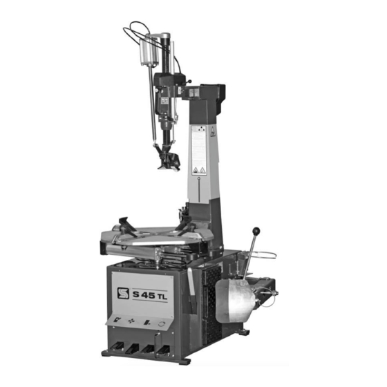
S 45 TL
S 45 TL
SMONTAGOMME AUTOMATICO
AUTOMATIC TYRE CHANGER
DEMONTE-PNEUS AUTOMATIQUE
AUTOMATISCHE REIFENMONTIERMASCHINE
DESMONTADORA AUTOMATICA DE NEUMATICOS
MANUALE ISTRUZIONI ............................
3
INSTRUCTION MANUAL ............................ 23
MANUEL D'INSTRUCTIONS ....................... 43
BETRIEBSANLEITUNG .............................. 63
MANUAL DE INSTRUCCIONES ................... 83
Publicidad
Capítulos
Tabla de contenido

Manuales relacionados para SICE S 45 TL


Resumen de contenidos para SICE S 45 TL
- Página 1 S 45 TL S 45 TL SMONTAGOMME AUTOMATICO AUTOMATIC TYRE CHANGER DEMONTE-PNEUS AUTOMATIQUE AUTOMATISCHE REIFENMONTIERMASCHINE DESMONTADORA AUTOMATICA DE NEUMATICOS MANUALE ISTRUZIONI ......INSTRUCTION MANUAL ......23 MANUEL D'INSTRUCTIONS ....... 43 BETRIEBSANLEITUNG ......63 MANUAL DE INSTRUCCIONES ....83...
- Página 2 ITALIANO • Manuale d’uso S 45 TL...
-
Página 3: Tabla De Contenido
5. TRASPORTO ............................5 6. INSTALLAZIONE ............................. 5 6.1 Luogo di installazione ........................5 6.2 Disimballo ............................6 6.3 Montaggio (solo S 45 TL GP) ........................6 6.4 Fissaggio al pavimento ........................7 6.5 Allacciamento pneumatico ........................7 6.6 Allacciamento elettrico ........................7 6.7 Installazione limitatore di corsa (optional) ....................8 7. -
Página 4: Generalita
ITALIANO • Manuale d’uso 1. GENERALITA’ Lo smontagomme SICE S 45 TL è una macchina realizzata per smontare e montare pneumatici di autovetture e veicoli industriali leggeri con cerchi da 12" a 27" e diametro max. 1100 mm (43”). Qualsiasi altro utilizzo è da ritenersi improprio e quindi irragionevole e non consentito. -
Página 5: Dispositivi Di Sicurezza
3,5 bar. La versione S 45 TL GP è inoltre dotata di una valvola di massima (1,Fig. A), situata sul serbatoio esterno, tarata a 11 bar. Questa valvola entra in funzione ogni qualvolta la pres- sione all'interno del serbatoio tende a superare gli 11 bar. -
Página 6: Disimballo
4) Aprire la fiancata sinistra dello smontagomme. 5) All’interno dello smontagomme sono presenti 2 tubi, provenienti dal dispo- sitivo di gonfiaggio, già predisposti con il raccordo a innesto rapido. Collegare il tubo (7, Fig. C4) contrassegnato dal bollino adesivo “A”, al corri- S 45 TL... -
Página 7: Fissaggio Al Pavimento
(posizionato sul cavo di alimentazione dello smontagomme). E' assolutamente obbligatorio che l'impianto sia corredato di una buona rete di terra. La macchina deve essere collegata ad interruttore automatico di alimentazione (differenziale) tarato a 30 mA. S 45 TL... -
Página 8: Installazione Limitatore Di Corsa (Optional)
8) Montare il supporto del grasso, distanziandolo dalla posizione originale tramite la staffa e le viti in dotazione al kit (vedi Fig. K/9). 9) Inserire il perno di regolazione (2, Fig. K/3) nel foro del limitatore di corsa contrassegnato dal numero 0. S 45 TL... -
Página 9: Identificazione Delle Parti
12- Gruppo filtro lubrificatore 13- Appoggio in gomma 14- Paletta stallonatrice 15- Leva di comando torretta TL 16- Torretta di montaggio/smontaggio TL 17- Leva pneumatico 18- Pedale di gonfiaggio (versione GP) 19- Unità analogica di gonfiaggio (versione GP) S 45 TL... -
Página 10: Identificazione Segnali Di Pericolo
Presenza tensione di rete Pericolo schiacciamento delle gambe Pericolo di fuoriuscita di un forte getto d'aria. durante la stallonatura Pericolo schiacciamento mani tra cerchio Pericolo dovuto allo spostamento laterale del e autocentrante durante la stallonatura braccio. S 45 TL... -
Página 11: Controllo Corretto Funzionamento
7) Azionare la leva di comando (15, Fig. D) verso il basso: si deve azionare il movimento dell’unghia di montaggio “leverless” (vedi Fig. E4); riportando la leva di comando in alto l’unghia deve ritornare nella posizione di riposo (vedi Fig. E5). S 45 TL... -
Página 12: Uso
ITALIANO • Manuale d’uso PER VERSIONE S 45 TL GP: Azionare il pedale di gonfiaggio (Fig. E6 in posizione 1: dalla testina di gonfiaggio deve uscire aria; azionare il pedale di gonfiaggio (Fig. E6) in posizione 2: dai fori presenti nei 4 scorrevoli di bloccaggio deve uscire un forte getto d’aria. - Página 13 RUN FLAT, RIBASSATI, UHP). Il braccio stallonatore dello smontagomme S 45 TL ha 2 posizioni di lavoro (vedi Fig. F1 ed F2): - la posizione di Fig. F1 viene consigliata per operare su ruote con cerchio di larghezza fino a 10”;...
-
Página 14: Bloccaggio Ruota
Non tenere le mani sulla ruota: il ritorno in posizione di “ lavoro “ del palo potrebbe causarne lo schiacciamento fra cerchio e torretta. 2) Premere, in posizione intermedia, il pulsante situato sulla maniglia (9, Fig. D) S 45 TL... - Página 15 N.B.: Nel caso il tallone tenda a restare nel canale agevolare l’operazione con l’ausilio della spatola in plastica (vedi Fig. G5). ATTENZIONE: Nel caso si operi su ruote con cerchio in ferro l’utilizzo della spatola in plastica è obbligatorio per evitare che il cerchio possa andare a danneggiare il tallone del pneumatico. S 45 TL...
-
Página 16: Montaggio
5 (vedi Fig. H1). ATTENZIONE : Se il pneumatico è dotato di sensore di pressione iniziare il montaggio con la valvola posizionata a ore 7 rispetto la torretta. S 45 TL... -
Página 17: Tallonatura E Gonfiaggio
RUOTE SPECIALI L’ S 45 TL dotato di appositi accessori, disponibili a richiesta, è in grado di operare su ruote speciali: PAX SYSTEM (con PT+KPX), SR Support Ring (con PT+KSR), Run Flat, ribassate, UHP (con PT). -
Página 18: Pneumatici Con Camera D'aria
(HUMP, DOUBLE HUMP, etc.). 6) Proseguire, sempre introducendo aria a brevi tratti e sempre verificando negli intervalli la pressione, fino al raggiungimento della pressione desiderata. S 45 TL GP PNEUMATICI CON CAMERA D’ARIA 1) Svitare il coprivalvola e l’interno valvola. -
Página 19: Accessori
Con lo smontagomme viene fornito un apposito catalogo nel quale sono elencati gli accessori disponibili. Tutti gli accessori SICE vengono sempre forniti completi di istruzione per l'eventuale montaggio sullo smontagomme ed il corretto utilizzo. Non utilizzare MAI accessori non originali. -
Página 20: Norme Anti Incendio
9) Passare la seconda cinghia fra i due scassi anteriori del piatto autocentrante come mo- strato in Fig. Z/1. 10) Con apposito anello di cinghia raccogliere, al di sopra della macchina, i capi delle cinghie di sostegno. 11) Sollevare e trasportare con dispositivo idoneo adeguatamente dimensionato. S 45 TL... -
Página 21: Accantonamento
Con il vostro aiuto si può ridurre la quantità di risorse naturali impiegate per la realizzazione di apparecchiature elettriche ed elettroniche, minimizzare l’uso delle discariche per lo smaltimento dei prodotti e migliorare la qualità della vita evitando che sostanze potenzialmente pericolose vengano rilasciate nell’ambiente. S 45 TL... -
Página 22: Dati Di Targa
ATTENZIONE: Se le indicazioni sopra elencate non riportano lo smontagomme ad un corretto funzionamento o si riscontrano anomalie di altro tipo, NON utilizzare lo smontagomme e chiamare immediatamente il servizio tecnico di assistenza. S 45 TL S 45 TL... - Página 23 6. INSTALLATION ............................25 6.1 Installation place ..........................25 6.2 Unpacking ............................26 6.3 Assembly (S 45 TL GP only) ......................26 6.4 Fixing to the ground ........................27 6.5 Pneumatic hook up .......................... 27 6.6 Electric hook up ..........................27 6.7 Installing the stroke limiter (optional) ....................
-
Página 24: General Information
ENGLISH • Instructions manual 1. GENERAL INFORMATION The SICE S 45 TL tyre changer has been specially designed to demount and mount car and light industrial vehicle tyres with rims from 12” to 27” and a maximum diameter of 1100 mm (43”). -
Página 25: Safety Devices
The machine is delivered in a carton box with pallet. Shipping weight is: - S 45 TL: 305 kg. - S 45 TL GP: 323 kg. The machine must be handled with a fork-lift truck with the forks positioned as shown in the figure B. -
Página 26: Unpacking
4) Open the tyre changer’s left-hand side panel. 5) Inside the tyre changer there are 2 hoses leading from the inflation device, already fitted with snap connectors. Connect the hose (7, Fig. C2) labelled “A” to the corresponding hose (9, S 45 TL... -
Página 27: Fixing To The Ground
It is absolutely essential that the system is equipped with a good grounding circuit. The machine must be connected to a power supply line circuit breaker set for 30mA. Note the required power draw as highlighted on the tag-plate fixed to the back of the tyre changer. S 45 TL... -
Página 28: Installing The Stroke Limiter (Optional)
8) Fit the grease pot holder, moving it away from its original position using the bracket and screws supplied in the kit (see Fig. K/9). 9) Fit the adjuster pin (2. Fig. K/3) into the hole marked 0 on the stroke limiter. S 45 TL... -
Página 29: Identification Of Parts
12- Filter and lubricator 13- Rubber tyre rest 14- Bead breaker (loosener) shoe 15- TL mounting/demounting head control lever 16- TL mounting/demounting head 17- Tyre lever 18- Inflation pedal (GP version) 19- Analogue inflation unit (GP version) S 45 TL... -
Página 30: Identifying Warning Signal
Hand-crushing hazard between rim and jaw during tyre locking. Danger: electric voltage Leg-crushing hazard during Air jet hazard bead-breaking Hand-crushing hazard between rim and Hazard due to sideways movement of the arm. self-centering chuck during bead breaking. S 45 TL... -
Página 31: Correct Operation Checks
7) Push the control lever (15, Fig. D) downwards: this should make the leverless mount hook (see Fig. E4) move; by pulling the control lever up the hook should go back to the rest position (see Fig. E5). S 45 TL... -
Página 32: Operation
ENGLISH • Instructions manual For S 45 TL GP version: Activate the inflation pedal (Fig. E6) in position 1: air must flow out of the inflation head; activate the inflation pedal (Fig. E6) in position 2: a powerful jet of air must flow out through the holes in the four locking slides. - Página 33 (especially when working on RUN FLAT, LOW PROFILE or UHP tyres). The bead breaker arm of the S 45 TL has 2 working positions (see Fig. G/4 and G/5): - the position shown in Fig. G/4 is recommended for working on wheels with rims up to 10”...
-
Página 34: Wheel Clamping
1) Depress the pedal (7, Fig. D) to bring the arm (11, Fig. D) to its working position. WARNING! Do not place your hands on the wheel: when moving the arm to its working position your hands could be crushed between the rim and the mounting head. S 45 TL... - Página 35 N.B.: If the bead remains in the wheel rim well, use the plastic spatula to facilitate the procedure (see Fig. G5). CAUTION: Always use the plastic spatula when working with steel wheel rims to prevent damage to the tyre bead. S 45 TL...
-
Página 36: Mounting
6) Guide the tyre with the hands so that the bead passes under the hooked part of the head, and seat as much as possible onto the wheel by pressing in approximately the 5 o’clock position (see Fig. H1). S 45 TL... -
Página 37: Bead Seating And Inflating
SPECIAL WHEELS When equipped with special optional accessories, the S 45 TL is able to work on special wheels: PAX SYSTEM (with PT+KPX), SR Support Ring (with PT+KSR) and Run Flat, low profile and UHP (with PT). The correct working procedures for these wheels are described in the instruction manuals provided with the specific accessories. - Página 38 Special take must be taken when seating beads on humped or double humped anti-bead breaking rims. 6) Continue to inflate the tyre with short bursts of air and constantly checking the pressure between bursts until the required pressure has been reached. S 45 TL GP TUBED TYRES 1) Remove the valve stem.
-
Página 39: Accessories
A catalogue containing a list of the accessories available is supplied with the tyre changer. All SICE accessories come with a complete set of instructions for mounting on tyre changers and correct use. USE ONLY ORIGINAL SPARES. Using accessories that are not original can affect the safety of the tyre changer and immediately cause the SICE warranty to become invalid. -
Página 40: Fire-Fighting
9) Pass the second strap between the two front slots on the turntable plate as shown in Fig. Z/1. 10) Gather the ends of the slings in a suitable ring above the machine. 11) Hoist and move the machine with a sufficiently strong lift truck. S 45 TL... -
Página 41: Storing
With your help it is possible to reduce the amount of natural resources used to produce electrical and electronic equipments, to minimize the use of landfills for the disposal of the products and to improve the quality of life by preventing that potentially hazardous substances are released in the environment. S 45 TL... -
Página 42: Data On Serial Plate
2) Check and correct any hose defects. Replace hose if damaged. WARNING: If, inspite of the above mentioned indications the tyre changer doesn’t work properly, do not use it and call for technical assistance. S 45 TL S 45 TL... - Página 43 5. TRANSPORT ............................45 6. INSTALLATION ............................45 6.1 Lieu de installation .......................... 45 6.2 Deballage ............................46 6.3 Montage (seulement S 45 TL GP) ......................46 6.4 Fixation au sol ..........................47 6.5 Raccordement pneumatique ....................... 47 6.6 Raccordement électrique ........................47 6.7 Installation du limiteur de course (option) ..................
-
Página 44: Generalites
FRANÇAIS • Manuel d’instructions 1. GENERALITES Le démonte-pneus SICE S 45 TL est une machine réalisée pour démonter et monter des pneumatiques de voitures et de véhicules utilitaires avec des jantes de 12” à 27” et un diamètre max. de 1100 mm (43”). -
Página 45: Dispositifs De Securite
La machine est fournie dans un emballage en carton avec palette. Le poids de la machine emballée est: - S 45 TL: 305 kg. - S 45 TL GP: 323 kg. Manutentionner la machine avec un chariot élévateur en plaçant les fourches dans les points indiqués (Fig. B). -
Página 46: Deballage
N.B. : Les éléments de l’emballage ne doivent pas être laissés à la portée des enfants car ils représentent des sources de danger. Les matériaux d’emballage polluants ou non biodégradables doivent être jetés dans des décharges prévus à cet effet. 6.3 MONTAGE (SEULEMENT S 45 TL GP) MONTAGE DU RESERVOIR : 1) Retirer les 4 vis TH M 8x16 déjà... -
Página 47: Fixation Au Sol
(placée sur le câble d’alimentation du démonte-pneus). Il est indispensable que le circuit soit équipé d’un bon réseau de mise à la terre. La machine doit être reliée à un disjoncteur d’alimentation (différentiel) calibré à 30 mA. S 45 TL... -
Página 48: Installation Du Limiteur De Course (Option)
Monter le support porte-graisse en l’espaçant de sa position d’origine avec la plaque et kit (voir Fig. K/9). les vis fournies en équipement au 9) Enfiler le pivot de réglage (2, Fig. K/3) dans le trou du limiteur de course portant le numéro 0. S 45 TL... -
Página 49: Identification Des Pieces
13 - Butée en caoutchouc 14 - Palette détalonneur 15- Levier commande tourelle de montage/démontage TL 16- Tourelle de montage/démontage TL 17- Levier pneumatique 18 - Pédale de gonflage (version GP) 19 - Unité analogique de gonflage (version GP) S 45 TL... -
Página 50: Identification Des Signaux De Danger
Danger: présence de courant électrique. pneumatique. Danger d’écrasement des jambes pendant Danger: Jet d’air puissant le détalonnage. Danger d’écrasement des mains entre la Danger dû au déplacement latéral du bras. jante et le mandrin pendant le détalonnage. S 45 TL... -
Página 51: Controle Du Bon Fonctionnement
7) Abaisser le levier de commande (15, Fig. D), ce qui provoque la levée du crochet de montage “leverless” (cf. Fig. E4) ; la remontée du levier de commande replace le crochet dans sa position de repos (cf. Fig. E5). S 45 TL... -
Página 52: Utilisation
FRANÇAIS • Manuel d’instructions POUR LA VERSION S 45 TL GP: Enfoncer la pédale de gonflage (Fig. E6) dans la position 1: de l’air doit s’échapper de la tête de gonflage. Actionner la pédale de gonflage (Fig. E6) dans la position 2: un jet d’air puissant doit sortir des trous des 4 éléments coulissant de blocage. - Página 53 (RUN FLAT, SURBAISSÉS, UHP). Le bras détalonneur du démonte-pneus S 45 TL a 2 positions de travail (voir Fig. F1 et F2) : - la position de la Fig. F1 est conseillée pour intervenir sur des roues avec jantes de largeur jusqu’à...
-
Página 54: Blocage De La Roue
2) Appuyer sur le bouton situé sur la poignée (9, Fig. D) (dans une position intermédiaire) pour faire descendre la tourelle (16, Fig. D). Lorsque la tourelle touche le pneu, tirer le bras vers la jante jusqu’à ce que la tourelle aille se S 45 TL... - Página 55 N.B. : En cas de difficulté à extraire le talon du creux, faciliter l’opération avec la spatule en plastique (voir Fig. G5). ATTENTION ! En cas de roue avec une jante en acier, l’utilisation de la spatule en plastique est obligatoire afin d’éviter que la jante endommage le talon du pneu. S 45 TL...
-
Página 56: Montage
6) Accompagner le pneu avec les mains, de façon à ce que le talon passe sous la partie en forme de griffe de la tourelle, et l’encastrer le plus possible sur la jante en l’écrasant à 5 heures environ (voir Fig. H1). S 45 TL... -
Página 57: Roues Speciales
ROUES SPECIALES Le S 45 TL peut être doté d’accessoires, fournis sur demande ; dans ce cas, il est en mesure d’opérer sur des roues spéciales : PAX SYSTEM (avec PT+KPX), SR Support Ring (avec PT+KSR), Run Flat, surbaissées, UHP (avec PT). - Página 58 (HUMP, DOUBLE HUMP, etc). 6) Continuer en introduisant de l’air par petites doses et en vérifiant la pression dans les intervalles, jusqu’à atteindre la pression désirée. S 45 TL GP PNEUMATIQUES AVEC CHAMBRE A AIR 1) Dévisser le capuchon de la valve et l’intérieur de la valve.
-
Página 59: Accessoires
Un catalogue spécial est fourni avec le démonte-pneus dénommé “ACCESSOIRES DEMONTE-PNEUS DE VOITURE” dans lequel sont répertoriés les accessoires disponibles. Tous les accessoires SICE sont fournis avec les notices d’emploi de montage sur le démonte-pneus et sur leur utilisation N’utiliser jamais des accessoires qui ne sont pas d’origine. -
Página 60: Normes Contre Les Incendies
9) Passer la deuxième courroie entre les deux rainures avant du plateau autocentreur comme illustré dans la Fig. Z/1. 10) Avec un anneau de courroie, recueillir, au-dessus de l’appareil, les bouts des cour- roies de soutien. 11) Soulever et transporter avec un dispositif ayant les capacités appropriées. S 45 TL... -
Página 61: Remisage
Avec votre aide, il sera possible de réduire la quantité de ressources naturelles nécessaires à la fabrication des appareils électriques et électro- niques, de minimiser l’usage des déchetteries pour l’élimination des produits et d’améliorer la qualité de la vie en évitant que des substances potentiellement dangereuses ne souillent la nature. S 45 TL... -
Página 62: Plaque Signaletique
ATTENTION: Si les indications ci-dessus ne permettent pas de remettre correctement en service le démonte-pneus ou s’il y a des anomalies de type différent, NE PAS utiliser le démonte-pneus et appeler immédiatement le S.A.V. S 45 TL S 45 TL... - Página 63 10.5 Aufziehen und Aufpumpen ....................... 77 11. ZUBEHÖR ............................79 12. WARTUNG ............................79 13. BRANDBEKÄMPFUNGSVORSCHRIFTEN .....................80 14. BEWEGEN DER MASCHINE ........................80 15. LAGERHALTUNG ..........................81 16. VERSCHROTTEN ...........................81 17. DATEN DES TYPENSCHILDS ........................82 18. FEHLERSUCHE .............................82 S 45 TL S 45 TL...
-
Página 64: Allgemeines
DEUTSCH • Betriebsanleitung 1. ALLGEMEINES Die Reifenmontiermaschine SICE S 45 TL ist eine Maschine zum Demontieren und Montieren von Pkw- und Lkw-Reifen mit Felgen von 12“ bis 27“ und max. Durchmesser von 1100 mm. (43“). Jede andere Verwendung ist als bestimmungswidrig und daher unzulässig zu betrachten. -
Página 65: Sicherheitsvorrichtungen
Reifenfüllvorrichtungen abgegebene Druck den Wert von 3,5 bar überschreitet. Die Version S 45 TL GP verfügt ferner über ein Überdruckventil (1, Abb. A), das sich am externen Druckluftspeicher befindet und auf 11 bar eingestellt ist. Dieses Ventil nimmt seine Funktion jedes Mal auf, wenn der Druck innerhalb des Druckluftspeichers auf über 11 bar ansteigt. -
Página 66: Auspacken
3) Die zwei von der Ableseeinheit ausgehenden Schläuche (7-8, Abb. C2) an der Bohrung auf der Rückseite der Reifenmontiermaschine einfügen (siehe Abb. C2). 4) Die linke Seitenwand der Reifenmontiermaschine öffnen. 5) Innerhalb der Reifenmontiermaschine befinden sich zwei von der S 45 TL... -
Página 67: Befestigung Am Boden
Spannungsschild angezeigt ist (auf dem Netzkabel der Reifenmontiermaschine angeordnet). Die Anlage muß unbedingt mit einem guten Erdungsnetz verbunden werden. Die Maschine muß an einen Leistungsschalter (Fehlerstromschalter) angeschlossen werden, der auf 30 mA eingestellt ist. S 45 TL... -
Página 68: Installation Des Wegbegrenzers (Option)
Fettbehälterhalterung mit dem im Bausatz mitgelieferten Distanzeisen und den (siehe Abb. K/9). Schrauben auf den vorgesehenen Abstand zur Originalposition montieren 9) Den Einstellbolzen (2, Abb. K/3) in die mit der Zahl 0 gekennzeichnete Bohrung des Wegbegrenzers einfügen. S 45 TL... -
Página 69: Kennzeichnung Der Teile
11 - Waagrechter Arm 12 - Filter und Öler 13 - Reifenanschlag aus Gummi 14 - Abdrückschaufel 15- Bedienhebel des Hakens 16- TL Montier-/Demontierkopf 17- Reifenhebeeisen 18 - Schaltpedal -Reifenfüllen (Version GP) 19 - Analoge Füllmessvorrichtung (Version GP) S 45 TL... -
Página 70: Kennzeichnung Der Warnsignale
Beim Radaufspannen besteht für die Hand Quetschgefahr zwischen Felge und Vorsicht: Spannungsführend. Spannklauen. Beim Abdrücken besteht für die Beine Vorsicht: Austritt kräftiger Druckluft. Quetschgefahr. Beim Abdrücken bersteht für die Hände Quetschgefahr zwischen Felge und Gefahr durch seitliche Schwenkbewegung des Spanntisch. Arms. S 45 TL... -
Página 71: Prüfung Auf Korrekten Betrieb
7) Den Bedienhebel (17, Abb. D) nach unten stellen: es muss die Bewegung des “hebellosen” (leverless) Montagehakens erfolgen (siehe Abb. E4); wenn man den Bedienhebel wieder nach oben stellt, muss der Haken in die Ruheposition zurückkehren (siehe Abb. E5). S 45 TL... -
Página 72: Benutzung
3) Den Abdrückerarm öffnen, indem man ihn von Hand nach außen schiebt. Das Rad gegen den Gummianschlag (13, Abb. D) legen und die Schaufel (14, Abb. D) an den Reifenwulst annähern, und zwar mit einem Abstand von 1 cm zum Felgenhorn (vgl. Abb. F). S 45 TL... - Página 73 Reifentyp es sich handelt (insbesondere im Fall von RUNFLAT-, NIEDERQUERSCHNITTS- oder UHP-Rädern). Der Abdrückerarm der Reifenmontiermaschine S 45 TL weist zwei Arbeitspositionen auf (siehe Abb. F1 und F2): - Die Position von Abb. F1 empfiehlt sich für Arbeiten an Rädern mit Felgenbreiten bis 10 Zoll.
-
Página 74: Radaufspannen
1) Das Pedal (7, Abb. D) drücken, um der Mast (8, Abb. D) wieder in die “Ar- beitsstellung” zu bringen. Die Hände nicht auf das Rad halten: Die Rückkehr des Arms in die “Arbeitsstellung” könte sonst dazu führen, daß die Hände zwischen Felge und Werkzeugkopf eingequetscht werden. S 45 TL... - Página 75 Hinw.: Falls der Wulst dazu neigt, im Felgenbett zu bleiben, mit der Kunststoffspachtel nachhelfen (siehe Abb. G5). ACHTUNG: Falls man an Rädern mit Felgen aus Stahl arbeitet, muss die Kunststoffspachtel immer verwendet werden um zu vermeiden, dass die Felge den Wulst des Reifens beschädigt. S 45 TL...
-
Página 76: Montage
Haken des Montagekopfes durchgeht und ihn so fest wie möglich auf der Felge einspannen, etwa in Position 5-Uhr (siehe Abb. H1). ACHTUNG: Wenn der Reifen mit Drucksensor ausgestattet ist, die Montage mit Ventil auf 7-Uhr in Bezug auf den Montagekopf beginnen. S 45 TL... -
Página 77: Aufziehen Und Aufpumpen
Uhrzeigersinn wird nur gebraucht, um etwaige Bedienungsfehler auszubessern. SPEZIALRÄDER Wird S 45 TL mit entsprechenden, auf Anfrage verfügbaren Zubehörteilen ausgestattet, können mit diesem Modell auch Spezialräder mon- tiert und demontiert werden: PAX SYSTEM (mit PT+KPX), SR Support Ring (mit PT+KSR), Runflat, Niederquerschnittsräder, UHP (mit PT). -
Página 78: Reifen Mit Schlauch
1) Ventilkappe und Ventilschaft abschrauben. 2) Die Reifenfülldüse auf das Ventil stecken und sicherstellen, daß sie korrekt einrastet. 3) Sicherstellen, daß Durchmesser von Felge und Reifen zueinander passen. 4) Sicherstellen, daß Felge und Reifen ausreichend geschmiert sind. Ggf. erneut ein- streichen. S 45 TL... -
Página 79: Zubehör
Zum Lieferumfang der Reifenmontiermaschine gehört ein Katalog, Darin sind die lieferbaren Zubehörteile aufgeführt. Alle SICE-Zubehörteile werden immer mit der dazugehörigen Anleitung für die etwaige Montage auf der Reifenmontiermaschine und die korrekte Benutzung ausgeliefert. Benutzen Sie stets Originalzubehörteile. Die Benutzung von Zubehör, das kein Originalteil ist, kann die Sicherheit des Reifenmontiergeräts in Frage stellen und führt auch zum sofortigen Verfall der Garantie von SICE. -
Página 80: Brandbekämpfungsvorschriften
9) Den zweiten Gurt um die beiden vorderen Spalten in der Spannscheibe herumführen, wie in Abb. Z/1 zu sehen ist. 10) Die Enden der Hebegurte am vorgesehenen Gurtring oberhalb der Maschine einfügen. 11) Die Maschine dann mit einem ausreichend tragfähigem Mittel heben und transportieren. S 45 TL... -
Página 81: Lagerhaltung
Mit Ihrer Hilfe lässt sich die Menge der natürlichen Ressourcen, die für die Realisierung von elektrischen und elektronischen Geräten benötigt werden, reduzieren, die Kosten für die Entsorgung der Produkte minimieren und die Lebensqualität erhöhen, da verhindert wird, dass giftige Substanzen in die Umwelt gebracht werden. S 45 TL... -
Página 82: Daten Des Typenschilds
ACHTUNG: Wenn es ihnen trotz der obigen Angaben nicht gelingt, die Reifenmontiermaschine korrekt zum Laufen zu bringen oder wenn Störungen irgendwelcher Art vorliegen, verwenden Sie die Maschine NICHT, sondern verständigen umghend den technishen Kundendienst. S 45 TL S 45 TL... - Página 83 5. TRANSPORTE ............................85 6. INSTALACION ............................85 6.1 Lugar de instalacion ......................... 85 6.2 Desembalaje ........................... 86 6.3 Montaye (solo S 45 TL GP) ........................ 86 6.4 Fijacion en el suelo .......................... 87 6.5 Conexion neumatica ......................... 87 6.6 Conexion electrica..........................87 6.7 Instalacion del limitador de carrera (opcional) ..................
-
Página 84: Generalidades
ESPANOL • Manual de instrucciones 1. GENERALIDADES La desmontadora SICE S 45 TL es una máquina realizada para desmontar y montar neumáticos de coches y vehículos industriales ligeros con llantas de 12” a 27” y diámetro máx. 1100 mm. (43”) Otros usos se consideran impropios y, por lo tanto, irracionales y no permitidos. -
Página 85: Dispositivos De Securidad
La máquina viene embalada en caja de cartón con palet. El peso de la máquina embalada es: - S 45 TL: 305 kg. - S 45 TL GP: 323 kg. Manipular la desmontadora mediante un fork-lift posicionando las horquillas en los puntos indicados (Fig. B). -
Página 86: Desembalaje
Nota: mantener el material de embalaje fuera del alcance de los niños ya que puede constituir un peligro. Eliminar el material de embalaje conforme a las normas vigentes si éste contiene sustancias nocivas o no es biodegradable. 6.3 MONTAJE (SÓLO S 45 TL GP) MONTAJE DEL DEPÓSITO: 1) Retirar los cuatro tornillos de cabeza hexagonal M8 x 16 colocados en la carcasa en los agujeros de fijación del depósito. -
Página 87: Fijacion En El Suelo
(colocada en el cable de alimentación de la desmontadora). Es totalmente obligatorio que la instalación eléctrica esté dotada de una buena red de tierra. La máquina debe ser conectada a un interruptor automático de alimentación (diferencial) ajustado a 30 mA. S 45 TL... -
Página 88: Instalacion Del Limitador De Carrera (Opcional)
8) Montar el soporte de la grasa, separándolo de la posición original mediante el estribo y los tornillos incluidos en el kit (véase Fig. K/9). 9) Introducir el perno de regulación (2, Fig. K/3) en el agujero del limitador de carrera marcado con el número cero. S 45 TL... -
Página 89: Identificacion De Las Partes
11- Brazo horizontal 12- Filtro/lubricador 13- Apoyo de goma 14- Pala destalonadora 15- Palanca de mando uña TL 16- Torre de montaje/desmontaje TL 17- Palanca neumático 18- Pedal de inflado (versión GP) 19- Unitad analógica de inflado (versión GP) S 45 TL... -
Página 90: Identificacion De Senales De Peligro
Peligro de aplastamiento de los pies Peligro de salida de un fuerte golpe de aire. durante la fase de destalonado. Peligro de aplastamiento de las manos entre lanta y autocentrante durante el Peligro debido al desplazamiento lateral del brazo destalonado. S 45 TL... -
Página 91: Control Del Correcto Funcionamiento
7) Empujar la palanca de mando (15, Fig. D) hacia abajo: la uña de montaje “leverless” (véase Fig. E4) empieza a moverse; al llevar la palanca de mando nuevamente hacia arriba, la uña vuelve a la posición de reposo (véase Fig. E5). S 45 TL... -
Página 92: Utilizacion
ESPANOL • Manual de instrucciones PARA VERSION S 45 TL GP: Accionar el pedal de inflado (Fig. E6) en posición 1. Debe salir aire de la cabeza de inflado. Accionar el pedal de inflado (Fig. E6) en posición 2. Debe salir un gran chorro de aire por los agujeros de las 4 correderas de bloqueo. - Página 93 (sobre todo en caso de operar con ruedas RUN FLAT, REBAJADAS o UHP). El brazo destalonador de la desmontadora de neumáticos S 45 TL cuenta con dos posiciones de trabajo (véanse Fig. F/1 y F/2): - la posición de Fig.
-
Página 94: Bloqueo De La Rueda
1) Pulsar el pedal (7, Fig. D) para colocar el brazo (11, Fig. D) en posición de trabajo. No poner las manos sobre la rueda: el retorno de la columna en posición de “trabajo” puede provocar su aplastamiento entre la llanta y la torre. S 45 TL... - Página 95 NOTA: En caso de que el talón tienda a quedarse en el canal, facilitar la operación con ayuda de la espátula de plástico (ver la Fig. G5). ATENCIÓN: En caso de que se opere en ruedas con llanta de acero, el uso de la espátula de plástico es obligatorio para evitar que la llanta pueda dañar el talón del neumático. S 45 TL...
-
Página 96: Montaje
5 (ver la Fig. H1). ATENCIÓN: Si el neumático está dotado de sensor de presión, comenzar el S 45 TL... -
Página 97: Montaje Del Segundo Talón
El sentido de rotación antihorario sirve solamente para remediar eventuales errores del operador. RUEDAS ESPECIALES El S 45 TL equipado con accesorios específicos, disponibles bajo pedido, está en condiciones de operar en ruedas especiales: PAX SYSTEM (con PT+KPX), SR Support Ring (con PT+KSR), Run Flat, rebajadas y UHP (con PT). -
Página 98: Neumaticos Con Camara De Aire
(HUMP, DOBLE HUMP, etc.). 6) Proseguir, siempre introduciendo aire a breves golpes y siempre verificando en los intervalos la presión, hasta conseguir la presión deseada. S 45 TL GP NEUMATICOS CON CAMARA DE AIRE 1) Desmontar el tapón y el interior de la válvula. -
Página 99: Accesorios
Los accesorios SICE se suministran con las intrucciones para un eventual montaje en la desmontadora y su uso correcto. No utilizar NUNCA accesorios no originales. La utilización de accesorios no originales puede perjudicar la seguridad de la desmontadora y provocar la inmediata anulación de la garantía SICE. 12. MANTENIMIENTO ORDINARIO ATENCION! Antes de cualquier operación de mantenimiento es necesario desconectar la desmontadora de las fuentes de... -
Página 100: Normas Antincendio
9) Pasar la segunda cinta entre las dos guías delanteras como muestra la fig. Z/1. 10) Mediante el respectivo anillo de correa, recoger por encima de la máquina los extremos de las correas de soporte. 11) Levantar y transportar con el dispositivo idóneo adecuadamente dimensionado. S 45 TL... -
Página 101: Almacenado
Con vuestra ayuda se puede reducir la cantidad de recursos naturales empleados en la fabricación de equipos eléctricos y electrónicos, mini- mizar el empleo de los vertederos para la eliminación de los productos y mejorar la calidad de la vida, evitando que sustancias potencialmente peligrosas sean vertidas en el entorno. S 45 TL... -
Página 102: Datos De Matricula
ATENCION: Si las indicaciones arriba mostradas no reportan la desmontadora a un correcto funcionamiento o si se encuentran anomalias de otro tipo, NO utilzar la desmontadora y llamar al servicio de asistencia técnica. S 45 TL S 45 TL... - Página 103 ITALIANO • Manuale d’uso DICHIARAZIONE CE DI CONFORMITÀ Noi SICE SPA, Via Modena 34, 42015 Correggio (RE), ITALIA, dichiariamo che il prodotto Smontagomme S 45 TL al quale questa dichiarazione si riferisce e di cui abbiamo costituito e detenia- mo il relativo fascicolo tecnico è conforme alle seguenti norme e/o documenti...
-
Página 104: Ec Declaration Of Conformity
ITALIANO • Manuale d’uso EC DECLARATION OF CONFORMITY We, SICE SPA, Via Modena 34 - 42015 CORREGGIO (RE), ITALY, do hereby declare, that the product S 45 TL Tyre Changer to which this statement refers, manufactured by us and for which we hold the relative technical dos-... -
Página 105: Declaración Ec De Conformidad
Die vorliegende Erklärung entspricht in Form und Inhalt den Vorgaben der Norm EN ISO/IEC 17050-1 und EN ISO/IEC 17050-2. DECLARACIÓN EC DE CONFORMIDAD La empresa abajo firmante, SICE SPA, Via Modena 34 - 42015 CORREGGIO (PU), ITALY, declara que el producto: Desmontadora de neumaticos S 45 TL al cual se refiere la presente declaración y del que hemos redactado y poseemos el correspondiente expediente... - Página 106 SICE reserves the right to modify its machine at any time without prior notice. SICE declines any and all liability for injury to persons or damage to things caused by use of the machine other than that speci- fied or failure to observe the instructions detailed in this manual.