Tabla de contenido
Publicidad
Idiomas disponibles
Idiomas disponibles
Enlaces rápidos
Model No.:
608695 – 2701
608696 – 2701 Pac
609239 – 2701 Can. Pac
608275 – 3301
608276 – 3301 Pac
609238 – 3301 Can. Pac
NOBLES
12875 RANSOM STREET
HOLLAND MI 49424 U.S.A.
CUSTOMER SERVICE: 1-800-365-6625
FAX: 1–800–678–4240
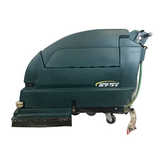
Speed Scrub
2701/3301
Automatic Floor Scrubber
Fregadora Automática
Operator and Parts Manual
Manual de Operación y de Piezas
ENGLISH - ESPAÑOL
t
608290
Rev. 02 (06-01)
Publicidad
Capítulos
Tabla de contenido

Manuales relacionados para Nobles Speed Scrub 2701


Resumen de contenidos para Nobles Speed Scrub 2701
- Página 1 Manual de Operación y de Piezas 608696 – 2701 Pac 609239 – 2701 Can. Pac 608275 – 3301 608276 – 3301 Pac 609238 – 3301 Can. Pac NOBLES 12875 RANSOM STREET HOLLAND MI 49424 U.S.A. 608290 CUSTOMER SERVICE: 1-800-365-6625 FAX: 1–800–678–4240...
-
Página 2: Tabla De Contenido
Printed in U.S.A. phone or mail from any authorized Service Center or Distributor. Nobles is a registered United States trademark of Tennant Company. Speed Scrub is a United States trademark of Tennant Company. This machine will provide excellent service. However, the best results will be obtained at minimum costs if: The machine is operated with reasonable care. -
Página 3: Safety Precautions
OPERATION 4. Before leaving or servicing machine: SAFETY PRECAUTIONS – Stop on level surface. – Turn off machine. 5. When servicing machine: This machine is suited to scrub floors in a indoor – Avoid moving parts. Do not wear loose environment and is not constructed for any other use. -
Página 4: Machine Components
OPERATION MACHINE COMPONENTS 1. Control Console 16. Rear Fill Port 2. Control Grips 17. Squeegee Assembly 3. Main/Drive ON/OFF switch 18. Recovery Tank 4. Vacuum ON/OFF Switch 19. Recovery Tank Lid 5. Brush ON/OFF Switch 20. Solution Fill Door 6. Battery Meter 21. -
Página 5: Machine Installation
OPERATION INSTALLING BATTERIES MACHINE INSTALLATION WARNING: Batteries emit hydrogen gas. Explosion or fire can result. Keep sparks and open flame away. Keep battery compartment open UNCRATING MACHINE when charging. Carefully check carton for signs of damage. Report FOR SAFETY: When servicing machine, wear damages at once to carrier. -
Página 6: Machine Setup
OPERATION 3. Carefully install batteries into compartment and arrange battery posts as shown (Figure 4). INSTALLING BRUSH OR PAD DRIVERS 1. Turn Main switch to the “OFF” position and pull out the Main Power circuit breaker button. FRONT FOR SAFETY: Before leaving or servicing machine, stop on level surface and turn off machine. -
Página 7: Filling Solution Tank
OPERATION 5. (For Pad Installation) Attach pads to pad drivers 3. Shut off solution flow. Pull solution flow lever before connecting drivers to motor hub. To attach completely back to shut off (Figure 9). pad to driver, remove plastic centerlock ring from pad driver. -
Página 8: Machine Operation
OPERATION 4. Turn on the MAIN, VACUUM and BRUSH switches. MACHINE OPERATION NOTE: The brush motors will not start until control grips are rotated. FOR SAFETY: Do not operate machine unless 5. Activate solution flow. Push solution flow lever operator manual is read and understood. slightly forward to activate. -
Página 9: While Operating Machine
OPERATION 5. During brief stops, you do not have to turn off WARNING: Flammable materials or reactive brush switch, the brush will automatically stop metals can cause explosion or fire. Do not pick when control grips are released. 6. While cleaning, view clear tube gallon marker for ATTENTION: Always start machine out slowly to remaining cleaning solution. -
Página 10: Draining Tanks
OPERATION DRAINING SOLUTION TANK DRAINING TANKS To drain leftover cleaning solution from solution tank, follow steps below: FOR SAFETY: Before leaving or servicing 1. Pull clear hose off hose barb at rear of machine machine, stop on level surface and turn off and drain solution into floor drain or bucket machine. -
Página 11: Battery Charging
OPERATION 4. Before charging batteries, check fluid level (A) in each battery cell. If battery plates (B) are exposed, BATTERY CHARGING add just enough distilled water to cover plates, level (A). Never add acid to batteries. DO NOT overfill. Batteries can overflow during charging due The following charging instructions are intended to expansion. -
Página 12: Machine Maintenance
OPERATION 7. Charger will automatically begin charging and 3. Drain and rinse tanks thoroughly. After draining automatically shut off when fully charged. tanks, hinge recovery tank until you can see vacuum intake hole at rear of tank. Remove any 8. After charger has turned off, unplug from wall clogging debris in hole if necessary. -
Página 13: Battery Maintenance
OPERATION BATTERY MAINTENANCE DRIVE CHAIN MAINTENANCE Inspect drive chain periodically for proper tension. WARNING: Batteries emit hydrogen gas. Chain should flex between 6.35mm (0.25 in) and Explosion or fire can result. Keep sparks and 12.7mm (0.50 in) from center. If chain flexes more open flame away. -
Página 14: Transporting Machine
OPERATION TRANSPORTING MACHINE RECOMMENDED STOCK ITEMS When transporting machine by use of trailer or truck, Refer to the Parts List section for recommended stock be certain to follow tie–down procedures below: items. Stock Items are clearly identified with a bullet preceding the parts description. -
Página 15: Trouble Shooting
OPERATION TROUBLE SHOOTING PROBLEM CAUSE SOLUTION No power, nothing runs. Batteries need charging. See CHARGING BATTERIES. Faulty battery(s). Replace battery(s). Loose battery cable. Tighten loose cable. Battery connection is improper. See BATTERY INSTALLATION. Faulty main switch Contact Service Center. Main Power circuit breaker has Determine cause and reset circuit tripped. - Página 16 OPERATION TROUBLE SHOOTING –continued PROBLEM CAUSE SOLUTION Poor squeegee pick up. Recovery tank water inlet is Empty recovery tank and tilt it plugged. Inlet is located at bottom sideways to locate inlet hole, of recovery tank. remove clogged debris. Drain hose plug is loose. Tighten drain plug.
-
Página 17: Specifications
OPERATION SPECIFICATIONS MODEL SPEED SCRUBt 2701 SPEED SCRUBt 3301 LENGTH 1500 mm (59 in) 1500 mm (59 in) WIDTH 740 mm (29 in) 890 mm (35 in) HEIGHT 1040 mm (41 in) 1040 mm (41 in) WEIGHT – 352kg (760 lbs) 355kg (765 lbs) W/ BATTERIES TANKS CAPACITY... - Página 18 OPERATION Speed Scrubt 2701/3301 (10–00)
-
Página 19: Datos De La Máquina
OPERACIÓN Este manual acompaña a todos los modelos estándar nuevos. En él se indican las instrucciones necesarias DATOS DE LA MÁQUINA para la utilización y el mantenimiento de la máquina. Lea el manual entero para comprender el funcionamiento de la máquina antes de utilizarla o Sírvase llenar los datos en el momento de la preparación para revisarla. -
Página 20: Operación
OPERACIÓN 3. ANTES DE ESTACIONAR O REVISAR LA MÁQUINA MEDIDAS DE SEGURIDAD – Asegúrese de que la máquina esté apagada, o tire hacia fuera del botón del cortacircuitos principal (MAIN). Esta máquina ha sido diseñada para barrer suelos de – Desconecte las baterías. -
Página 21: Componentes De La Máquina
OPERACIÓN COMPONENTES DE LA MÁQUINA 1. Panel de control 13. Pedal para elevar el cepillo 2. Mandos giratorios de control 14. Manguera de vaciado del depósito de 3. Interruptor principal (MAIN) y de recuperación Encendido/Apagado de la transmisión 15. Manguera de vaciado del depósito de 4. -
Página 22: Instalación De La Máquina
Cuatro baterías de 6 voltios, de ciclo profundo, de 305 haciéndola rodar porque podría averiarla. amp–hora; pieza Nobles número 130870. Las dimensiones máximas de las baterías son 178 mm (7 plg) de ancho x 308 mm (12–1/8 plg) de largo x 356 FIJACIÓN DEL CONJUNTO DE LA ESCOBILLA DE... -
Página 23: Preparación De La Máquina
OPERACIÓN ATENCIÓN: Para evitar que los motores 4. Conecte los cables a los bornes de la batería en el arranquen accidentalmente, asegúrese de tirar orden numérico indicado en la etiqueta (ROJO EN hacia fuera del botón del cortacircuitos principal EL POSITIVO Y NEGRO EN EL NEGATIVO) (MAIN) antes de instalar las baterías. -
Página 24: Importante
OPERACIÓN 2. Eleve el cabezal del cepillo, pise con fuerza la parte inferior del pedal de elevación del cepillo para elevarlo (Figura 5). FIG. 7 6. Conecte los impulsores del cepillo/de la almohadilla a los cubos del motor. Alinee los (3) FIG. -
Página 25: Llenado Del Depósito De La Disolución
OPERACIÓN ADVERTENCIA: Utilice únicamente LLENADO DEL DEPÓSITO DE LA DISOLUCIÓN productos químicos de limpieza no inflamables. 1. Empuje o dirija la máquina a la estación de llenado. Levante la escobilla de goma y el cepillo FUNCIONAMIENTO DE LA MÁQUINA durante el transporte. 2. -
Página 26: Durante La Utilización De La Máquina
OPERACIÓN 4. Bajada del cabezal del cepillo: Pise con fuerza la parte superior del pedal de elevación del cepillo y empuje dicho pedal hacia delante para liberarlo (Figura 13). FIG. 15 7. Gire lentamente los mandos giratorios de control hacia delante para comenzar la operación de barrido. -
Página 27: Cortacircuitos
OPERACIÓN ATENCIÓN: No permita que el agua o la espuma ATENCIÓN: No siga utilizando la máquina cuando se introduzcan en el tubo vertical de aspiración la aguja del indicador de carga de la batería se porque podría averiar el motor de aspiración. El encuentre en la zona roja porque podría dañar la flotador de cierre no evitará... -
Página 28: Vaciado De Los Depósitos
OPERACIÓN VACIADO DEL DEPÓSITO DE LA DISOLUCIÓN VACIADO DE LOS DEPÓSITOS Para vaciar los restos de disolución del depósito de la disolución haga lo siguiente: ATENCIÓN: Levante la escobilla de goma y el 1. Extraiga la lengüeta de la manguera transparente cepillo al transportar la máquina a la zona de con marcas de la parte posterior de la máquina vaciado. -
Página 29: Carga De Las Baterías
CARGA DE LAS BATERÍAS Las instrucciones de carga mostradas a continuación son exclusivamente para los cargadores Nobles. Si no dispone de un cargador de baterías Nobles, utilice un cargador con las características que se nombran a continuación para evitar el deterioro de las baterías. -
Página 30: Mantenimiento De La Máquina
OPERACIÓN 6. Enchufe el cargador en un enchufe de pared con toma de tierra después de conectar el cargador a la máquina (Figura 23). ENCHUFE ENCHUFE CONECTADO CONECTADO A TIERRA A TIERRA (3 ORIFICIOS) CLAVIJA DE CONEXION FIG. 24 A TIERRA 3. -
Página 31: Mantenimiento Mensual
OPERACIÓN 2. Controle el nivel de agua (A) de cada elemento de MANTENIMIENTO MENSUAL todas las baterías después de la carga semanal de la batería. El nivel del agua debe alcanzar la 1. Controle si la tensión de la cadena de impulsión parte inferior de los tubos (B). -
Página 32: Mantenimiento De La Cadena De Impulsión
OPERACIÓN 5. Pase las cintas de sujeción por la parte superior MANTENIMIENTO DE LA CADENA DE IMPULSIÓN de la máquina y sujételas al suelo del remolque o camión. Puede ser necesario el instalar varios Controle periódicamente si la tensión de la cadena de soportes de sujeción en el suelo de su camión o impulsión es la correcta. -
Página 33: Localización De Averías
OPERACIÓN LOCALIZACIÓN DE AVERÍAS PROBLEMA CAUSA SOLUCIÓN No hay alimentación, no fun- Defectuoso principal interruptor. Contactar con el Servicio Técnico. ciona nada. Las baterías necesitan ser Consultar el apartado de CARGA DE LAS cargadas. BATERÍAS. Batería(s) defectuosa(s). Sustituir la(s) batería(s). Cable de la batería flojo. - Página 34 OPERACIÓN LOCALIZACIÓN DE AVERÍAS – CONTINUACIÓN PROBLEMA CAUSA SOLUCIÓN El flujo de la disolución es La palanca del flujo de la disolu- Empujar la palanca del flujo de la disolución insuficiente o nulo. ción no ha sido activada. hacia delante. Tubería o filtro de la disolución Extraer la manguera y limpiarla con aire comprimido.
-
Página 35: Especificaciones
OPERACIÓN ESPECIFICACIONES MODELO SPEED SCRUBt 2701 SPEED SCRUBt 3301 LONGITUD 1500 mm (59 inch) 1500 mm (59 inch) ANCHURA 740 mm (29 inch) 890 mm (35 inch) ALTURA 1040 mm (41 inch) 1040 mm (41 inch) PESO – CON BATERÍAS 352kg (760 lbs) 355kg (765 lbs) CAPACIDAD DE LOS DEPÓSITOS... -
Página 36: Electrical Diagrams
(Brush Motors) Main Brush Brush & Breaker Breaker Breaker VACUUM Drive MOTOR Breaker SOLENOID 3 (Vacuum Motor) SPEED CONTROL CIRCUIT BOARD 24 VOLTS D.C. (4 X 6 VOLTS) DRIVE RIGHT LEFT MOTOR BRUSH BRUSH MOTOR MOTOR CHARGER PLUG Nobles (11–97) - Página 37 POTENTIOMETER CHARGER PLUG SPEED CONTROL CIRCUIT BOARD MAIN SWITCH Main Breaker FLASHER LIGHTS & SOLENOID 1 DRIVE Drive Breaker MOTOR BRUSH SWITCH SOLENOID 2 RIGHT LEFT BRUSH BRUSH BREAKER BREAKER BRUSH MOTORS VACUUM SWITCH SOLENOID 3 VACUUM MOTOR Nobles (11–97)
-
Página 38: Parts List
PARTS LIST LISTA DE PIEZAS REPLACEMENT BRUSHES AND PAD DRIVER GROUP CEPILLO DEL REEMPLAZO Y GRUPO DEL MANDO DE LA ALMOHADILLA Speed Scrubt 2701/3301 (10–00) - Página 39 PARTS LIST LISTA DE PIEZAS REPLACEMENT BRUSHES AND PAD DRIVER GROUP CEPILLO DEL REEMPLAZO Y GRUPO DEL MANDO DE LA ALMOHADILLA PART # DESCRIPTION QTY. PART # DESCRIPTION QTY. ∇ ∇ DPAD DRIVER ASM 14” (2701) 240227 BRUSH, POLY SCRUB PK/2 (2701) 240232 DPAD DRIVER ASM 17”...
-
Página 40: Recovery Tank Group
PARTS LIST LISTA DE PIEZAS RECOVERY TANK GROUP CONJUNTO DESPOSITO RECUPERAR Speed Scrubt 2701/3301 (10–00) - Página 41 PARTS LIST LISTA DE PIEZAS RECOVERY TANK GROUP CONJUNTO DESPOSITO RECUPERAR PART # DESCRIPTION QTY. PART # DESCRIPTION QTY. ∇ DCABLE, REC TANK SUPPORT 100162 ASM STANDPIPE W/NIPPLE 140960 ∇ 100759 STANDPIPE, RM–NAT 603437 ASM, DRAIN HOSE DPLUG, EXPANSION 1–1/2”DIA 606088 FITTING, 1–1/2”...
-
Página 42: Chassis Group
PARTS LIST LISTA DE PIEZAS CHASSIS GROUP CONJUNTO TELAIO Speed Scrubt 2701/3301 (06–01) - Página 43 HINGE, COVER 600796 HOSE, DRAIN W/LEVEL INDCTR 140706 RIVET, POP 1/8 608915 CLAMP, HOSE 2 WIRE 3701.6 SCREW, #6X3/8 608448 DECAL, SPEED SCRUB 2701 140032 WASHER, #6 FLAT 608447 DECAL, SPEED SCRUB 3301 602529 FILTER, SCREEN 608184 DECAL, NOBLES LOGO 140300 CLAMP, INSULATED 1/2”...
-
Página 44: Control Console Group
PARTS LIST LISTA DE PIEZAS CONTROL CONSOLE GROUP CONJUNTO CONSOLA DE CONTROLES Speed Scrubt 2701/3301 (10–00) - Página 45 PARTS LIST LISTA DE PIEZAS CONTROL CONSOLE GROUP CONJUNTO CONSOLA DE CONTROLES PART # DESCRIPTION QTY. PART # DESCRIPTION QTY. DMETER, BATTERY VOLTAGE 24V 606020 230649 PIN, HANDLE ADJUSTMENT DSWITCH, ROCKER SPST 130816 230648 PIN, HANDLE ADJUSTMENT LOCK DSWITCH, ROCKER DPST 240V 130764 140415 SPRING, LOCK PIN...
-
Página 46: Lever Group
PARTS LIST LISTA DE PIEZAS LEVER GROUP CONJUNTO DE PALANCAS Speed Scrubt 2701/3301 (10–00) - Página 47 PARTS LIST LISTA DE PIEZAS LEVER GROUP CONJUNTO DE PALANCAS PART # DESCRIPTION QTY. PART # DESCRIPTION QTY. 200816 GRIP, HANDLE 1/4 X 1 X 2 1/4 140201 SCREW, 3/8–16X3/4 230680 HANDLE, VALVE HANDLE 230658 HANDLE, SQUEEGEE LEVER 140202 SCREW, 3/8–16X1 140016 WASHER, 1/4 LOCK 140017...
-
Página 48: Electrical Panel Group
PARTS LIST LISTA DE PIEZAS ELECTRICAL PANEL GROUP CONJUNTO CONSOLA ELÉCTRICO Speed Scrubt 2701/3301 (10–00) - Página 49 PARTS LIST LISTA DE PIEZAS ELECTRICAL PANEL GROUP CONJUNTO CONSOLA ELÉCTRICO PART # DESCRIPTION QTY. PART # DESCRIPTION QTY. 100151 GASKET, TUBE–ADAPTER 140887 SCREW, 10–24X3/8 230664 ADAPTER, TUBE 140031 WASHER, #10 EXTERNAL 140424 SPRING, TUBE–ADAPTER 140012 WASHER, 3/16 FLAT 230939 BRACKET, TUBE WELDMENT 100234 COVER, ELECTRICAL PANEL...
-
Página 50: Drive Wheel Group
PARTS LIST LISTA DE PIEZAS DRIVE WHEEL GROUP CONJUNTO RUEDA DE MANDO Speed Scrubt 2701/3301 (06–01) - Página 51 PARTS LIST LISTA DE PIEZAS DRIVE WHEEL GROUP CONJUNTO RUEDA DE MANDO PART # DESCRIPTION QTY. PART # DESCRIPTION QTY. 600349 SCREW, 5/16–18 X 2–3/4 140510 NUT, 1/4–20 HEXJAM 140015 WASHER, 5/16 SPLITLOCK 230941 BRACKET, FRONT LIFT GUIDE 140232 SCREW, 3/8–16X1–1/4 140015 WASHER, 5/16 630450...
-
Página 52: Brush Drive And Solution Hose Group
PARTS LIST LISTA DE PIEZAS BRUSH DRIVE AND SOLUTION HOSE GROUP ACCIONAMIENTO DEL CEPILLO Y GRUPO DE MANGUERA DE SOLUCION Speed Scrubt 2701/3301 (06–01) - Página 53 PARTS LIST LISTA DE PIEZAS BRUSH DRIVE AND SOLUTION HOSE GROUP ACCIONAMIENTO DEL CEPILLO Y GRUPO DE MANGUERA DE SOLUCION PART # DESCRIPTION QTY. PART # DESCRIPTION QTY. 100764 COVER, BRUSH MOTOR 140417 CLIP, SPRING ∇ DMOTOR, W/GEARBOX 3/4HP IMP 130491 25732 WASHER, 1.25 X .359 X .093...
-
Página 54: Skirt Group
PARTS LIST LISTA DE PIEZAS SKIRT GROUP CONJUNTO JUEGO Speed Scrubt 2701/3301 (10–00) - Página 55 PARTS LIST LISTA DE PIEZAS SKIRT GROUP CONJUNTO JUEGO PART # DESCRIPTION QTY. PART # DESCRIPTION QTY. 603154 SCREW, M8 X 1.25 X 40 230942 BRACKET, SKIRT MOUNT 140015 WASHER, 5/16 SPLITLOCK 608697 SKIRT, LEFT SIDE GREEN (2701) DWHEEL, 76 DIA X 22 WD RUBBER 630450 101071 SKIRT, LEFT SIDE GRAY (2701)
-
Página 56: Squeegee Control Group
PARTS LIST LISTA DE PIEZAS SQUEEGEE CONTROL GROUP GROUPO DE CONTROL DE LA ESCOBILLA DE GOMA Speed Scrubt 2701/3301 (06–01) - Página 57 PARTS LIST LISTA DE PIEZAS SQUEEGEE CONTROL GROUP GROUPO DE CONTROL DE LA ESCOBILLA DE GOMA PART # DESCRIPTION QTY. PART # DESCRIPTION QTY. DHOSE, VAC 1.5 X 30” W/ CUFFS 611847 140546 NUT, 5/16–18 230441 SHAFT, LIFT 611777 BRACKET, SQUEEGEE MOUNT 140209 SCREW, 1/4–20 X 2–1/2 140221...
-
Página 58: Curved Squeegee Group
PARTS LIST LISTA DE PIEZAS CURVED SQUEEGEE GROUP CONJUNTO PALETA ENCORUADO Speed Scrubt 2701/3301 (06–01) - Página 59 PARTS LIST LISTA DE PIEZAS CURVED SQUEEGEE GROUP CONJUNTO PALETA ENCORUADO PART # DESCRIPTION QTY. PART # DESCRIPTION QTY. ∇ 612029 ASM., SQUEEGEE LINATEX & GUM 611661 CASTING, SQUEEGEE RUBBER 965MM (38 IN) (2701 MODEL) (2701 MODEL) 611401 CASTING, SQUEEGEE 612030 ASM., SQUEEGEE LINATEX &...
-
Página 60: Options
OPTIONS OPCIONES ESt KIT ESt JUEGO Speed Scrubt 2701/3301 (10–00) - Página 61 OPTIONS OPCIONES ESt KIT ESt JUEGO PART # DESCRIPTION QTY. PART # DESCRIPTION QTY. ∇ 605555 KIT, ES 25160 TUBING, 5/8X1.25’ 603166 SWITCH, LIQUID LEVEL W/NUT 150415 FITTING, ELBOW 90° 630138 FILTER, SCREEN 578008000 SCREW, M5X.8X30 DTIMER, 24VDC, RANGE: 30SEC 630385 FITTING, 3/4M NIPPLE 630145...
-
Página 62: Squeegee Wand Assembly
OPTIONS OPCIONES SQUEEGEE WAND ASSEMBLY GROUPE D’ASPIRATION ET RACLETTE À MAIN PART # DESCRIPTION QTY. PART # DESCRIPTION QTY. ∇ DASM., WAND DOUBLE BEND DHOSE, VAC 1–1/2X10’ 190928 160481 6108.1 WAND, DOUBLE BEND 160451 CONNECTOR, VAC HOSE 13840 SQUEEGEE ASM PUSH/PULL ∇...