Tabla de contenido
Publicidad
Idiomas disponibles
Idiomas disponibles
Enlaces rápidos
Publicidad
Capítulos
Tabla de contenido

Manuales relacionados para Dalla Corte DC PRO XT


Resumen de contenidos para Dalla Corte DC PRO XT
- Página 1 DC PRO XT manuale UTENTE - user manual benutzerhandbuch - manual de usuario...
- Página 3 XT indice - contents inhalt - Ìndice Manuale utente (Versione originale) User manual (Translated from the original) Benutzerhandbuch (Vom original) Manual de usuario (Traducido del original)
-
Página 5: Tabla De Contenido
Manuale utente Dotazione della macchina espresso Avvertenze generali e di sicurezza Predisposizione per l’installazione Messa in funzione ed utilizzo Descrizione della macchina Display gruppo Preparazione del caffè espresso Preparazione del latte caldo Erogazione acqua calda Utilizzo dello scaldatazze Utilizzo MCS (opzionale) Regolazione del flusso Manutenzione periodica a cura dell’utente Menù... -
Página 6: Targa Dati
MODEL Cxxxxxxxx DC-PROXT YEAR 2018 X GROUPS Maximum water pressure 0.6MPa Coffee circuit pressure 1,1Mpa DALLA CORTE S.R.L. VIA ZAMBELETTI, 10 l XX 0,15Mpa 20021 BARANZATE (ITALY) 380 - 400 V 3N 50/60Hz MADE IN ITALY 220 - 230 V... -
Página 7: Dotazione Della Macchina Espresso
1. Dotazione della macchina espresso • n.3-4 filtri 2 tazze H26 (il numero varia in base al modello 2 o 3 gruppi) • n.2 filtri 1 tazza h23 • n.1 portafiltro completo 1 tazza • n.2-3 portafiltri completi a 2 tazze (il numero varia in base al modello 2 o 3 gruppi) •... -
Página 8: Avvertenze Generali E Di Sicurezza
Le illustrazioni presenti in questo manuale hanno carattere puramente indicativo. Dalla Corte si riserva la facoltà di apportare variazioni alla produzione ed al manuale senza che ciò comporti l’obbligo di aggiornare produzione e manuali precedenti. - Página 9 Prima di collegare l’apparecchio accertarsi che i dati di targa siano rispondenti a quelli della rete di distribuzione elettrica. La targa dati si trova al di sotto della bacinella sul lato sinistro della macchina. L’istallazione deve essere effettuata in ottemperanza alle norme vigenti secondo le istruzioni del costruttore e da personale qualificato.
- Página 10 responsabile per eventuali danni causati da usi impropri, erronei ed irragionevoli. L’apparecchio non è idoneo per l’utilizzo da parte dei bambini, persone con ridotte capacità fisiche, sensoriali, mentali o carenti di conoscenze a meno che non sia data supervisione e istruzione. Le temperature massime e minime di immagazzinamento devono essere comprese nel range 0 °C, +55 °C.
- Página 11 • In caso di guasto e/o di cattivo funzionamento della macchina, spegnerla completamente, astenendosi da qualsiasi tentativo di riparazione diretta. Quindi, rivolgersi esclusivamente al Servizio Assistenza Tecnica autorizzato dal costruttore. • L’apparecchiatura deve essere installato in modo che la superficie più elevata sia almeno a 1,2 metri di altezza.
- Página 12 Non ostruire le griglie di aspirazione e/o di dissipazione in particolare dello scaldatazze. Il cavo di alimentazione non deve essere sostituito dall’utente. In caso di danneggiamento, spegnere l’apparecchio e per la sua sostituzione rivolgersi esclusivamente al personale qualificato. Allorché si decida di non utilizzare più un apparecchio di questo tipo si raccomanda di renderlo inoperante, dopo aver staccato la macchina dall'impianto elettrico, tagliare il cavo di alimentazione.
-
Página 13: Trasporto E Movimentazione
Trasporto e movimentazione ATTENZIONE PERICOLO DI URTO O SCHIACCIAMENTO La macchina viene trasportata in casse di legno su pallet singolarmente; la macchina è fissata al pallet tramite gli appositi bulloni. Prima di procedere a qualsiasi operazione di trasporto o movimentazione l’operatore deve indossare guanti e scarpe antinfortunistici ed una tuta con elastici alle estremità. -
Página 14: Predisposizione Per L'installazione
3. Predisposizione per l’installazione L’apparecchiatura va posta su una superficie che possa garantire un appoggio sicuro della stessa. In fase di predisposizione degli impianti prevedere un’apertura A (Fig.1) di almeno 10x10 cm sulla superficie di appoggio per poter effettuare i collegamenti con gli impianti nel vano sottostante B (Fig.1). L’apparecchiatura deve essere alimentata esclusivamente con acqua fredda destinata al consumo umano, a norma e in ottemperanza alle regole nazionali. - Página 15 Connessioni Fig.1 1 Rubinetto alimentazione idrica 2 Tubi flessibili per connessione idrica 3 Addolcitore acqua (opzionale) 4 Tubo di scarico 5 Sifone di scarico 6 Cavo di alimentazione elettrica 7 Interruttore alimentazione elettrica A Apertura sul piano di appoggio B Vano inferiore | 15...
-
Página 16: Messa In Funzione Ed Utilizzo
4. Messa in funzione ed utilizzo dell’apparecchiatura Eseguire le seguenti istruzioni con l’aiuto dello schema riportato in Fig.1. • Aprire il rubinetto dell’alimentazione idrica (1 Fig.1). • Accendere l’interruttore dell’impianto elettrico (7 Fig.1) e ruotare in sen- so orario l’interruttore generale dell’apparecchiatura (1 Fig.2); verificare quindi che il display si accenda. - Página 17 • Immediatamente dopo inizia la fase di riscaldamento della caldaia, durante la quale il simbolo lampeggerà. • Durante il riscaldamento della caldaia i gruppo erogatori possono già essere utilizzati. Quando la caldaia arriva alla temperatura prestabilita il simbolo termina di lampeggiare e il segnalatore acustico emette 2 bip per indicare che tutta l’apparecchiatura è...
-
Página 18: Descrizione Della Macchina
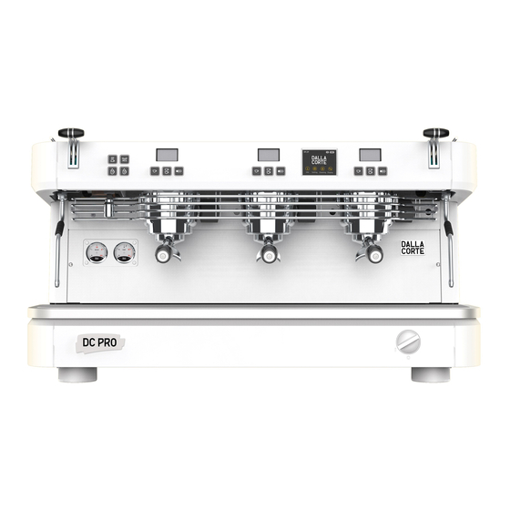
5. Descrizione della macchina Fig.2 1 Interruttore generale 2 Piedini regolabili 3 Bacinella 4 Lancia vapore 5 Leva vapore 6 Uscita acqua calda 7 Manometro caldaia 8 Manometro pompa 9 Gruppo erogatore 10 Portafiltro 18 |... - Página 19 Fig.3 Pulsantiera gruppo P0 Pulsante selezione 1 (default caffè singolo corto) P1 Pulsante selezione 2 (default caffè doppia corto) P2 Pulsante selezione 3 (default erogazione continua) Pulsante touch P3 Pulsante selezione 4 (default flush) Pulsantiera servizi P4 Pulsante interruttore scaldatazze P5 Pulsante dose 1 acqua calda P6 Pulsante interruttore MCS P7 Pulsante dose 2 acqua calda...
-
Página 20: Display Gruppo
6. Display gruppo Campo d’impiego e uso previsto Una volta che il gruppo erogatore raggiunge la temperatura di set dopo l’accensione questa è la schermata che visualizziamo sui display dei singoli gruppi. Possiamo visualizzare i seguenti dati: • CRONOMETRO: viene visualizzato 00.0 s 95.0 °... - Página 21 sopracitati ma apparirà solo la scritta OFF come illustrato nell’immagine che segue. Al momento della riaccensione i parametri rimarranno lampeggianti fino al raggiungimento della tempe- ratura impostata. Funzione bilancia Durante l’erogazione, oltre ad ave- re il peso totale sempre visualizzato alla voce P del display, viene data la possibilità...
-
Página 22: Preparazione Del Caffè Espresso
7. Preparazione del caffè espresso Per ottenere sempre un buon caffè è necessario tenere i portafiltri (10 Fig.2) sempre inseriti nei gruppi erogatori (9 Fig.1) al fine di mantenerli sempre alla corretta temperatura. Per preparare il caffè espresso seguire la seguente procedura: •... -
Página 23: Preparazione Del Latte Caldo
8. Preparazione del latte caldo Versare del latte in un bricco con il manico. Introdurre il tubo vapore (4 Fig.2) nel bricco ed aprire il rubinetto del vapore (5 Fig.2) relativo al tubo del vapore utilizzato. Quando la temperatura del latte è quella desiderata chiudere il rubinetto del vapore. -
Página 24: Erogazione Acqua Calda
9. Erogazione acqua calda Questa apparecchiatura è dotata di due pulsanti di prelievo dell’acqua calda per infusi, dosati a tempo. Mettere un recipiente (resistente a temperature di almeno a 125 °C) sotto il diffusore di uscita dell’acqua calda (6 Fig.2) e premere uno dei due pulsanti di erogazione di acqua calda P5-P7 (Fig.3). -
Página 25: Utilizzo Dello Scaldatazze
10. Utilizzo dello scaldatazze In particolari condizioni ambientali 10:51 Mar 28 Ago 2018 attorno all’apparecchiatura si cre- ano circolazioni di aria fredda che possono compromettere e deviare il normale flusso di aria calda dal- la caldaia verso le tazze, e impedire quindi a queste ultime di raggiunge- re la temperatura corretta. - Página 26 La funzione scaldatazze prevede 2 potenze: premendo il pulsante P4 una volta, lo scaldatazze funziona ad intermittenza fornendo un riscaldamento medio. In questo caso, l’icona scaldatazze sul display lampeggia. Premendo per la seconda volta il pulsante P4 si imposta invece il riscaldamento massimo e l’icona sul display rimane fissa.
-
Página 27: Utilizzo Mcs (Opzionale)
11. Utilizzo MCS (opzionale) L’MCS (Milk Control System) è un sistema automatico di riscaldamento del latte. Attraverso l’utilizzo dell’MCS è possibile ottenere una quantità di latte riscaldata ad una temperatura prestabilita, con una crema di latte comparabile a quella ottenuta dai migliori baristi. Per utilizzare l’MCS è... -
Página 28: Regolazione Del Flusso
12. Regolazione del flusso La macchina è dotata del sistema MFR (Manual Flow Regulator) che permette di regolare il flusso dell’acqua erogata da ogni singolo gruppo. Per la regolazione del flusso occorre utilizzare l’utensile incorporato nel pressino speciale con testa a brugola. La procedura qui di seguito mostra come regolare il flusso in modo appro- priato: 1. - Página 29 3. Inserire l’utensile nel foro del copriscarico ed accertarsi di posizionarlo in modo che la testa della brugola si inserisca propria- mente nella testa della vite. 4. Erogare l’acqua utilizzando il pulsante di erogazione manuale facendo attenzione a non mettere le mani al di sotto del gruppo erogatore per evitare ustioni.
-
Página 30: Manutenzione Periodica A Cura Dell'utente
6. Verificare il corretto flusso tramite i g/s indicati nella voce F sul display del gruppo. 7. Al termine della regolazione riavvitare il tappo sul pannello copriscarico. 13. Manutenzione periodica a cura dell’utente ATTENZIONE Il costruttore non può essere considerato responsabile per i danni a persone, cose o animali causate da una scorretta esecuzione della manutenzione. - Página 31 Pulizia delle parti di carrozzeria Pulire tutte le parti di carrozzeria con un panno umido non gocciolante evitando di usare detergenti o spugne abrasive. Pulizia giornaliera delle parti a contatto con il caffè Tutte le sere, o al termine dell’uso dell’apparecchiatura, sganciare i portafiltri (10 Fig.2) dai gruppi erogatori (9 Fig.2) e togliere i filtri dai portafiltri.
- Página 32 10:51 Pulizia Mar 28 Ago 2018 Caldaia Info Settaggi Pulizia Gruppi • Quindi selezionare il gruppo che si • Premere CLEANING sul display intende pulire. principale. • Ripetere la procedura anche per gli altri gruppi erogatori o premere INDIETRO per tornare alla schermata principale. •...
- Página 33 Lavaggio della caldaia (giornaliera) Per garantire che l’acqua calda per gli infusi sia sempre pulita e potabile effettuare giornalmente il lavaggio della caldaia. Per eseguire il lavaggio della caldaia procedere come segue: • Inserire un tubo flessibile nel bocchettone di uscita dell’acqua calda sull’apparecchiatura da un lato e nel lavandino dall’altro.
-
Página 34: Pulizia Periodica
Pulizia periodica Circa ogni 3-6 giorni (a seconda della mole di lavoro giornaliera) smontare le doccette ed i portadoccette situati sotto i gruppi erogatori e pulirli con l’apposito spazzolino che si trova in dotazione. Rimontare queste parti prestando attenzione a riposizionare tutte le parti correttamente, in caso contrario si potrebbe causare una cattiva estrazione del caffè... -
Página 35: Menù Info - Visualizzazione Delle Informazioni Utili
14. Menù INFO Visualizzazione delle informazioni utili La prima voce che visualizziamo sul Menù INFO display principale riguarda le infor- Info mazioni utili. Premiamo INFO per accedere a que- sto menù: Luci 10:51 Contalitri Mar 28 Ago 2018 Allarmi Grinder Info Info Settaggi... - Página 36 14.1 Luci Premere CONTALITRI per accedere Questa voce del menù serve ad ac- a questo menù: cendere e spegnere l’illuminazione Contalitri anteriore e posteriore della macchi- na espresso. Premere sulla scritta LUCI per attivare o disattivare le Litri utilizzati stesse. Ultimo cambio 14.2 Contalitri 27/08/2018...
- Página 37 14.3 Allarmi La massima capacità di memoria è di Questo menù permette di visualiz- 20 allarmi. Superato questo numero, zare se ci sono state delle anomalie i più vecchi vengono eliminati perché nel funzionamento dell’apparecchia- sovrascritti da quelli nuovi. tura tramite lo storico degli allarmi Premere INDIETRO per tornare al intervenuti.
- Página 38 • Nella colonna Grinder visualizziamo Premere CONTACICLI per accedere i grinder presenti nel sistema GCS. a questo menù: • Nella colonna Conteggio visualiz- Contacicli ziamo il conteggio del sistema GCS. • Nella colonna Errori visualizziamo EV Gruppo 1 gli errori misurati dal sistema GCS EV Gruppo 2 nelle erogazioni considerate nella EV Gruppo 3...
- Página 39 Premere CONTATORI per entrare in 14.6.1 Gruppo 1-2-3 questo menù: In questo menù visualizzo i contato- ri dei caffè dosati erogati dal gruppo Contatori selezionato. Premere su GRUPPO 1-2-3 per ac- Gruppo 1 cedere a questo menù: Gruppo 1 Gruppo 2 Selezione Cont.
- Página 40 Premere INDIETRO per tornare al • Nella colonna “Selezioni” visualiz- menù precedente. ziamo l’elenco dei tasti che vengono contati. 14.6.2 Caffè totali • Nella colonna “Contatori Parziali” In questo menù visualizzo il conteg- visualizziamo il conteggio dei con- gio di tutti caffè dosati erogati su tutti tatori parziali.
- Página 41 Premere INDIETRO per tornare al 14.6.6 Release firmware menù precedente. In questo menù visualizzo la versione del firmware della macchina espres- 14.6.5 Lavaggi so attualmente installato. Questo menu permette di vedere i Premere FIRMWARE per accedere a contatori dei cicli di lavaggio effet- questo menù: tuati al fine di verificare se l’opera- Firmware...
-
Página 42: Accensione E Spegnimento Delle Unità Gruppi E Caldaia
15. Accensione e spegnimento delle unità gruppi e caldaia Dalla schermata principale, sele- Gruppi zionando GRUPPI si accede al menù che permette di accendere e spegne- re i singoli gruppi e la caldaia vapore. 10:51 Mar 28 Ago 2018 Caldaia Al momento della disattivazione di un gruppo erogatore, sul display gruppo del gruppo selezionato ve-... - Página 43 Al momento della disattivazione della caldaia vapore vedremo inve- ce scomparire il simbolo dalla schermata principale. 10:51 Mar 28 Ago 2018 Info Settaggi Pulizia Gruppi | 43...
-
Página 44: Programmazione
16. Programmazione Dalla schermata principale, premen- Entrando nel menù SETTINGS si vi- do SETTINGS, si possono program- sualizza la seguente schermata: mare diverse impostazioni come la temperatura dei gruppi e caldaia e l’abilitazione del timer settimanale. 10:51 Mar 28 Ago 2018 16.0 Password Info Settaggi... - Página 45 A questo punto si può accedere al Settings menù. Service Menù SETTINGS: Reset Settings Dati Macchina Regolazione display Grinder Settings Contalitri Reset Dati Settings Regolazione display Temperature Pulsantiere Timer Cambio password Dosi | 45...
- Página 46 16.1 Temperature 16.2 Timer Questo menù serve per accedere alla Questa apparecchiatura è dotata di schermata di regolazione delle tem- un timer settimanale di accensione perature dei singoli gruppi e della e spegnimento per ogni gruppo ero- caldaia vapore. gatore e per la caldaia. Premere TEMPERATURA per acce- Tutti i timer sono programmabili in dere a questo menù:...
-
Página 47: Programmazione Timer
• Se si desidera attivare il timer se- Timer Gruppo 3 lezionare “SI” nella voce “Attivazio- ne” e procedere premendo sulla 00:00 Lunedì freccia alla voce “Programma”. 00:00 Martedì 16.2.1 Programmazione Timer Sicurezza Mercoledì Timer Copia in Gruppo 3 Imposta Copia Nella schermata di programmazione Gruppo 2... - Página 48 • Selezionare a destra il giorno che si - ON: il gruppo caldaia rimarrà vuole programmare che, una volta in uno stato di sicurezza ad una selezionato, diventerà su sfondo temperatura di 60° per il gruppo nero. Scorrere la settimana utiliz- e 80°...
- Página 49 • Premere INCOLLA a fianco al grup- Cambio password po nel quale si vogliono copiare le regolazioni. 11111 Timer Gruppo 3 Imposta Copia Gruppo 2 Imposta Incolla Gruppo 1 Imposta Incolla In questa schermata visualizziamo la password attualmente impostata. Caldaia Imposta Incolla •...
-
Página 50: Allarmi
• Digitare la nuova password utilizzan- • Premere INDIETRO per tornare al do il tastierino numerico. Nel caso menù precedente. si sbagliasse a digitare, premere per tornare alla cifra precedente. 17. Allarmi Questa apparecchiatura è dotata di un sistema di controllo elettronico che, oltre a gestire tutte le funzioni operative, verifica anche il corretto funziona- mento di tutti i componenti. - Página 51 Allarme Causa Effetto Timeout Questo allarme interviene quando si esegue Spegnimento del gruppo; Gr.1 una erogazione sul gruppo 1 tramite il pulsante premere DEL sul display P5 di erogazione continua per più di 120 secondi per cancellare l’allarme Timeout Questo allarme interviene quando si esegue Spegnimento del gruppo;...
- Página 52 Allarme Causa Effetto Sonda Questo allarme interviene quando la sonda Blocco del riscaldamento caldaia di temperatura della caldaia è fuori campo della caldaia; inter premere DEL sul display per cancellare l’allarme Sonda Questo allarme interviene quando la sonda Blocco del riscaldamento caldaia di temperatura della caldaia è...
- Página 53 Allarme Causa Effetto Timeout Questo allarme interviene quando entro Blocco del riscaldamento sonda 5 minuti dall’accensione del gruppo 1, del gruppo 1; Gr.1 questo non ha raggiunto la temperatura premere DEL sul display di 50 °C per cancellare l’allarme Sonda Questo allarme interviene quando la sonda Blocco del riscaldamento Gr.1...
- Página 54 Allarme Causa Effetto Sonda Questo allarme interviene quando la sonda Blocco del riscaldamento Gr.2 di temperatura del gruppo 2 è fuori campo del gruppo 2; interrotta premere DEL sul display per cancellare l’allarme Sonda Questo allarme interviene quando la sonda Blocco del riscaldamento Gr.2 di temperatura del gruppo 2 è...
- Página 55 Allarme Causa Effetto Sonda Questo allarme interviene quando Blocco del riscaldamento del Gr.3 la sonda di temperatura del gruppo 3 gruppo 3; premere DEL sul display in corto è fuori campo per cancellare l’allarme Alta Questo allarme interviene quando Blocco del riscaldamento del temperatura la temperatura del gruppo 3 è...
- Página 56 Allarme Causa Effetto Timeout Questo allarme interviene quando Blocco dell’autolivello; premere DEL livello l’autolivello non riesce a riportare sul display per cancellare l’allarme la quantità dell’acqua in caldaia al e far ripartire l’autolivello livello di lavoro previsto entro il tempo impostato nella programmazione Livello di Questo allarme interviene quando...
- Página 57 Allarme Causa Effetto Perdita Questo allarme interviene quando Premere DEL sul display per cancellare dati si ha una perdita dati nel EEPRO, cioè l’allarme e rivolgersi al servizio tecnico quando si perdono tutte le impostazioni autorizzato definite all’installazione e la macchina torna a lavorare con i dati di fabbrica Orologio Questo allarme interviene quando...
- Página 58 58 |...
- Página 59 User manual Espresso machine equipment General warnings Preparing for installation Commissioning and use of the equipment Description of the machine Brew group display Preparing an espresso coffee Preparing hot milk Hot water supply Use of the cup warmer Use of the MCS Flow regulation Periodic maintenance by the user Displaying useful information...
-
Página 60: Identification Plate
MODEL Cxxxxxxxx DC-PROXT YEAR 2018 X GROUPS Maximum water pressure 0.6MPa Coffee circuit pressure 1,1Mpa DALLA CORTE S.R.L. VIA ZAMBELETTI, 10 l XX 0,15Mpa 20021 BARANZATE (ITALY) 380 - 400 V 3N 50/60Hz MADE IN ITALY 220 - 230 V... -
Página 61: Espresso Machine Equipment
1. Espresso machine equipment • no. 3-4 filters 2 cups H26 (the number varies according to the model, 2 or 3 groups) • no. 2 filters 1-cup H23 • no. 1 complete 1 cup portafilter set • no. 2-3 complete 2 cup portafilter sets (the number varies according to the model, 2 or 3 groups) •... -
Página 62: General Warnings
The manufacturer reserves the right to modify this manual at any time without notice and without having to update previous versions. The illustrations in this manual are purely indicative. Dalla Corte reserves the right to make changes to the machines and to manuals without the obligation to update previous versions of machines or manuals. - Página 63 Before connecting the machine, make sure that the data on the information plate corresponds to the characteristics of the electric power supplied. The information plate is located below the tray on the left side of the machine. Installation must be carried out in compliance with the regulations in force, according to the manufacturer's instructions, and by qualified personnel.
- Página 64 The machine is not suitable for use by children, persons with reduced physical, sensory, or mental capacity or anyone lacking suitable knowledge, unless supervision and instruction are provided. The maximum and minimum storage temperatures must be within the range of 0 °C to +55 °C. The operating temperature must be within the range of +5 °C to +30 °C.
- Página 65 • The equipment must be installed in such a way that the highest side is at least 1.2 meters high. • To guarantee the efficiency of the equipment and its proper operation it is essential to follow the manufacturer's instructions, carrying out all ordinary maintenance.
-
Página 66: Transport And Handling
If you decide to no longer use this equipment, after having disconnected the machine from the electrical system, cut it. The continuous sound pressure level is less than 70 dB. WARNING BURN HAZARD When using the steam wand, pay close attention, do not put your hands under it, and do not touch it immediately after use. - Página 67 Before engaging in any transport or handling operation, the operator must be sure to wear safety gloves and shoes and a suit with elastic bands at the wrists and ankles. Transport on pallets must be carried out with a suitable lifting device (e.g.
-
Página 68: Preparing For Installation
3. Preparing for installation The machine must be installed on a surface that guarantees a safe and stable support. When preparing the installation site, provide an at least 10x10 cm opening A (Fig.1) on the support surface to enable the connections with the necessary utilities in the space below B (Fig.1). -
Página 69: Connections Overview
Connections overview Fig.1 1 Water tap 2 Flexible water hoses 3 Water softener (optional) 4 Drain hose 5 Drain siphon 6 Electric supply cable 7 ON/OFF electrical supply switch A Hole on support surface B Under counter space | 69... -
Página 70: Commissioning And Use Of The Equipment
4. Commissioning and use of the equipment Carry out the following instructions with the help of the diagram shown in Fig.1. • Open the water supply tap (1 Fig.1). • Turn on the electrical power switch (7 Fig.1) and turn the machine's main switch clockwise (1 Fig.2);... - Página 71 • Immediately after the boiler heating phase begins during which the boiler heating symbol will start flashing. • While the boiler heats up the brew groups may already be used. When the boiler reaches the pre-set temperature, the symbol stops flashing and the buzzer emits 2 beeps to indicate that all the equipment is in the nominal condition of use.
-
Página 72: Description Of The Machine
5. Description of the machine Fig.2 1 Main switch 2 Adjustable feet 3 Tray 4 Steam wand 5 Steam valve 6 Hot water outlet 7 Boiler pressure gauge 8 Pump pressure gauge 9 Brew group 10 Portafilter 72 |... - Página 73 Fig.3 Brew group push-button panel P0 Selection button 1 (default single small shot coffee) P1 Selection button 2 (default double small shot coffee) P2 Selection button 3 (default continuous brewing) Touch-screen button P3 Selection button 4 (default flush) Service push-button panel P4 Cup warmer switch button P5 Hot water dose button 1 P6 MCS switch button...
-
Página 74: Brew Group Display
6. Brew group display Brew group display description Once the brew group reaches the pre-set temperature after the machine is switched on, the following screen is shown on each of the individual brew group displays. The following information is di- splayed: 00.0 s 95.0... - Página 75 main display, the screen will no longer display the above parameters and only the word OFF will appear as shown in the image below. When the brew group is switched back ON, all parameters will flash until the pre-set temperature is re- ached.
-
Página 76: Preparing An Espresso Coffee
7. Preparing an espresso coffee To always make a quality coffee keep the portafilters (10 Fig.2) inserted in the brew groups (9 Fig.1) so as to maintain them at the proper temperature. To prepare an espresso coffee follow the procedure below: •... -
Página 77: Preparing Hot Milk
8. Preparing hot milk Pour some milk into a frothing jug/pitcher equipped with a handle. Insert the steam wand (4 Fig.2) in the jug and open the steam valve (5 Fig.2). When the milk reaches the desired temperature, close the steam valve. Once this operation is complete, clean the steam wand with a damp cloth to prevent milk residues from accumulating on it. -
Página 78: Hot Water Supply
9. Hot water supply This machine is equipped with two hot water dispensing buttons for infusions, dosed by time. Place a container (resistant to temperatures of at least 125 °C) under the hot water outlet (6 Fig.2) and press one of the two hot water supply buttons (P5 or P7 Fig.3). -
Página 79: Use Of The Cup Warmer
10. Use of the cup warmer In particular environmental condi- 10:51 tions around the equipment, the cir- Tue 28 Aug 2018 culation of cold air may compromise and deviate the normal flow of hot air from the boiler towards the cups, and therefore prevent them from re- aching the proper temperature. - Página 80 The cup warmer has 2 settings: by pressing the P4 button once, the cup warmer operates intermittently providing a medium level of heat. In this case, the cup warmer icon on the display flashes. By pressing the P4 button a second time, the maximum heating setting is activated and the icon on the display remains fixed.
-
Página 81: Use Of The Mcs
11. Use of the MCS The MCS (Milk Control System) is an automatic milk heating system. With the MCS it is possible to froth milk at a pre-set temperature. The frothed milk obtained is comparable to that of the best baristas. Using the MCS is as simple as putting a quantity of cold milk in a jug, placing it under the MCS wand, and pressing the P6 button (Fig.3). -
Página 82: Flow Regulation
12. Flow regulation The machine is equipped with a MFR (Manual Flow Regulator) system that allows the regulation of the water flow supplied by each brew group. To adjust the flow, use the tool featuring a hexagonal end which is incorporated in the special coffee tamper supplied with the machine. - Página 83 3. Insert the tool in the hole located in the discharge cover and be sure to position it so that the hexagonal end is well inserted in the screw head. 4. Dispense the water by pressing the rele- vant water supply button, making sure not to put your hands under the outlet to avoid burns.
-
Página 84: Periodic Maintenance By The User
6. Check the flow by means of the g/s infor- mation indicated next to the letter F on the brew group display. 7. At the end of the regulation procedure, screw the cap back onto the discharge cover panel. 13. Periodic maintenance by the user WARNING The manufacturer shall not be liable for any injury or damage caused to people, things, or animals as a result of the lack of proper maintenance of... - Página 85 Cleaning of body parts Wipe down all body parts with a damp cloth and avoid using abrasive detergents or sponges. Daily cleaning of parts in contact with coffee At the end of the work day, unhook the portafilters (10 Fig.2) from the brew groups (9 Fig.2) and remove the filters from the portafilters themselves.
- Página 86 10:51 Cleaning Tue 28 Aug 2018 Boiler Info Settings Cleaning Groups • Then select the brew group to be • Tap CLEANING on the main di- cleaned. splay. • Repeat the procedure for the other brew groups or press BACK to return to the main screen.
- Página 87 Boiler washing (daily) To ensure that the hot water for infusions is always clean and potable, clean the boiler daily. Proceed as follows to wash the boiler: • Insert one end of a flexible hose in the hot water outlet on the machine and the other end in the sink.
-
Página 88: Periodic Cleaning
Periodic cleaning Approximately every 3-6 days (depending on the amount of daily work) disassemble the showers and the shower heads located under the brew groups and clean them with the special brush provided. Reassemble these parts paying attention to reposition all the parts correctly, otherwise it could lead to bad coffee extraction and damage to the brew groups. -
Página 89: Displaying Useful Information
14. Displaying useful information The first item seen on the main display concerns useful information. Tap INFO to access this menu: INFO menu: 10:51 Info Tue 28 Aug 2018 Light Liters Meter Alarms Info Settings Cleaning Groups Grinder Info Grinder Cycles Meter General Meters Firmware... - Página 90 14.1 Lights Tap LITER METER to access this This menu item is used to switch the menu: front and back lighting of the espres- Liters Meter so machine on and off. Tap the word LIGHTS to turn them on or off. Used liters 14.2 Liter meter This menu allows you to view the li-...
- Página 91 14.3 Alarms The maximum memory capacity is 20 This menu allows you to see if there alarm events. Once this number is were any anomalies in the opera- exceeded, the oldest alarm is dele- tion of the equipment through the ted because it is overwritten by the alarms log.
- Página 92 • In the Grinder column the grinders Tap CYCLES METER to access this in the GCS system are displayed. menu: • In the Meter column the GCS sy- Cycles Meter stem count is displayed. • The Errors column contains the er- EV Gr.1 rors detected by the GCS system EV Gr.2...
- Página 93 Tap GENERAL METERS to enter this 14.6.1 Brew Groups 1-2-3 menu: This menu displays the meters re- garding the dosed coffee brewed by General Meters the selected brew group. Tap GROUP 1-2-3 to access this menu: Group 1 Group 1 Group 2 Selection Part.
- Página 94 14.6.2 Total coffee • The "Partial Counters" column di- This menu displays the count of all splays the count of the partial coun- the dosed coffee brewed on all the ters. brew groups. • The "Total Counters" column di- splays the count of the total coun- Tap BACK to return to the previous menu.
- Página 95 14.6.5 Washing cycle 14.6.6 Firmware release This menu displays the counters of This menu displays the version of the the washing cycles carried out in or- firmware currently installed on the der to check whether the machine espresso machine. operator performs ordinary mainte- Tap FIRMWARE to access this menu: nance on a daily basis.
-
Página 96: Turning The Brew Groups And Boiler On And Off
15. Turning the brew groups and boiler on and off From the main screen, by selecting Groups GROUPS you access the menu that al- lows the individual brew groups and the boiler to be turned on and off. 10:51 Tue 28 Aug 2018 Boiler When a brew group is deactivated, the word OFF will be displayed on the... - Página 97 In contrast, when the boiler is deacti- vated, the symbol will disappear from the main screen. 10:51 Tue 28 Aug 2018 Info Settings Cleaning Groups | 97...
-
Página 98: Programming
16. Programming From the main screen, by tapping Entering the SETTINGS menu the SETTINGS, you can program diffe- following screen is displayed: rent settings such as the group and boiler temperature and the activa- tion of the weekly timer. 10:51 Tue 28 Aug 2018 16.0 Password Info... - Página 99 At this point the menu can be acces- Settings sed. Service SETTINGS Menu: Reset Settings Data Machine Regulation display Grinder Settings Liters Meter Reset Data Settings Regulation display Temperatures Keyboards Timer Change password Doses | 99...
- Página 100 16.1 Temperatures 16.2 Timer This menu is used to access the This machine is equipped with a we- screen to adjust the individual brew ekly on/off timer for each brew group groups and boiler temperatures. and for the boiler. Tap TEMPERATURES to access this All the timers can be programmed menu: independently from each other and...
-
Página 101: Timer Programming
16.2.1 Timer Programming In the programming screen it is pos- sible to select the days of the week Timer and the relative times for the auto- matic timer to turn on and off. Group 3 Copy Timer Group 3 Group 2 Copy 00:00 Monday... - Página 102 16.2.2 Copy Timer Group 3 From the timer screen, you can copy the weekly settings from one unit to 08:17 Monday another. • Tap COPY next to the brew group Tuesday 12:17 that is already set. Safety Wendsday Timer Copy in Group 3 Copy Group 2...
-
Página 103: Change Password
16.3 Change password Timer From this submenu it is possible to change the password to access the Group 3 Copy menu. Tap CHANGE PASSWORD to access Paste Group 2 this menu: Group 1 Paste Change password Boiler Paste 11111 • Tap BACK to return to the previous menu. - Página 104 • Type the new password using the • To change it, tap the key and the numeric keypad. If you make a first digit of the password will start typing error, tap to go back to to flash. the previous digit. •...
-
Página 105: Alarms
17. Alarms This equipment is equipped with an electronic control system that, in addition to managing all the operational functions, also verifies the correct operation of all the components. If an anomaly occurs to a certain function, it is logged and/or displayed by means of an alarm message on the main screen. - Página 106 Alarm Cause Effect Timeout This alarm is triggered when brewing The brew group is switched Gp.3 on group 3 by means of the P5 continuous off; tap DEL on the display delivery button for more than 120 seconds to cancel the alarm Steam This alarm is triggered during steam delivery The steam supply is...
- Página 107 Alarm Cause Effect Steam sensor This alarm is triggered when the MCS The MCS function is blocked; interrupted temperature sensor is out of range tap DEL on the display to cancel the alarm Steam This alarm is triggered when the MCS The MCS function is blocked;...
- Página 108 Alarm Cause Effect Gp.2 This alarm is triggered when brew group 2 Brew group 2 heating sensor has not reached the temperature of 50 °C blocked; tap DEL on the timeout within 5 minutes from being activated display to cancel the alarm Gp.2 This alarm is triggered when the brew Brew group 2 heating...
- Página 109 Alarm Cause Effect Gp.3 This alarm is triggered when the brew Brew group 3 heating blocked; sensor group 3 temperature sensor is out of tap DEL on the display to cancel short circuited range the alarm High This alarm is triggered when the Brew group 3 heating blocked;...
- Página 110 Alarm Cause Effect Level This alarm is triggered when Autofill function is blocked; tap DEL timeout the autofill function fails to bring on the display to cancel the alarm the water in the boiler to the and restart the autofill pre-established level within the time set in the programming Safety...
- Página 111 Alarm Cause Effect Data This alarm is triggered when there Tap DEL on the display to cancel loss is a data loss in the EEPRO, that is, the alarm and contact an authorized when all the settings defined during technical service provider installation are lost and the machine returns to the factory defaults Clock...
- Página 112 112 |...
- Página 113 Benutzerhandbuch Ausstattung der Espressomaschine Allgemeine Hinweise Installationsvorbereitung Inbetriebnahme und Benutzung des Geräts Beschreibung der Maschine Brühgruppenanzeige Zubereitung des Espressos Zubereitung der heißen Milch Heißwasserausgabe Benutzung des Tassenwärmers Benutzung des MCS Flussregulierung Regelmäßige Wartung durch den Benutzer Anzeige nützlicher Informationen Ein- und Ausschalten der Brühgruppeneinheiten und des Boilers 150 Programmierung Alarme Schaltplan...
- Página 114 MODEL Cxxxxxxxx DC-PROXT YEAR 2018 X GROUPS Maximum water pressure 0.6MPa Coffee circuit pressure 1,1Mpa DALLA CORTE S.R.L. VIA ZAMBELETTI, 10 l XX 0,15Mpa 20021 BARANZATE (ITALY) 380 - 400 V 3N 50/60Hz MADE IN ITALY 220 - 230 V...
-
Página 115: Ausstattung Der Espressomaschine
1. Ausstattung der Espressomaschine • 3-4 Filter 2 Tassen H26 (die Anzahl variiert je nach 2- oder 3-gruppigem Modell) • 2 Filter 1 Tasse H23 • 1 kompletter Siebträger f. 1 Tasse • 2-3 komplette Siebträger f. 2 Tassen (die Anzahl variiert je nach 2- oder 3-gruppigem Modell) •... -
Página 116: Allgemeine Hinweise
2. Allgemeine Hinweise ACHTUNG Lesen Sie die Bedienungsanleitung vor Gebrauch sorgfältig durch. Lesen Sie die in dieser Anleitung enthaltenen Warnhinweise vor Gebrauch sorgfältig durch, da sie wichtige Informationen über Sicherheit, Installation, Gebrauch und Wartung enthalten. Ein unsachgemäßer Gebrauch kann zu Schäden an Personen, Tieren oder Gegenständen führen, für die der Hersteller nicht verantwortlich gemacht werden kann. - Página 117 Vergewissern Sie sich vor dem Anschluss des Gerätes, dass die Angaben auf dem Typenschild mit den Angaben des Stromnetzes übereinstimmen. Das Typenschild befindet sich unter der Wasserauffangschale auf der linken Seite der Maschine. Die Installation muss unter Beachtung der geltenden Vorschriften nach den Anweisungen des Herstellers und durch qualifiziertes Personal durchgeführt werden.
- Página 118 Dieses Gerät darf nur für den Zweck verwendet werden, für den es ausdrücklich konzipiert wurde. Jeder andere Gebrauch gilt als unangemessen und unsachgemäß. Der Hersteller haftet nicht für Schäden, die durch unsachgemäßen, falschen oder vernunftswidrigen Gebrauch entstehen. Das Gerät ist nicht für Kinder oder Personen geeignet, deren körperliche, sensorische und geistige Fähigkeiten eingeschränkt sind oder denen es an Erfahrungen und Kenntnissen fehlt.
- Página 119 • Im Falle eines Ausfalls und/oder einer Fehlfunktion der Maschine schalten Sie diese vollständig aus und unterlassen Sie jeden Versuch einer direkten Reparatur. Wenden Sie sich nur an den vom Hersteller autorisierten technischen Kundendienst. • Das Gerät muss so installiert werden, dass die höchste Oberfläche mindestens 1,2 Meter hoch ist.
- Página 120 Das Netzkabel darf nicht vom Benutzer ausgetauscht werden. Schalten Sie im Schadensfall das Gerät aus und wenden Sie sich für den Austausch ausschließlich an qualifiziertes Personal. Wenn Sie sich entscheiden, ein solches Gerät nicht mehr zu verwenden, Nachdem Sie die Maschine von der elektrischen Anlage getrennt haben, Zerschneiden des Kabels.
-
Página 121: Transport Und Handhabung
Transport und Handhabung ACHTUNG: KOLLISIONS- UND QUETSCHGEFAHR Die Maschine wird in Holzkisten auf Paletten einzeln transportiert. Die Maschine ist mit den entsprechenden Schrauben an der Palette befestigt. Vor dem Transport oder der Handhabung muss der Bediener Schutzhand- schuhe, Sicherheitsschuhe und einen Anzug mit Gummibündchen tragen. Der Transport auf Paletten muss mit einer geeigneten Hebevorrichtung (z. -
Página 122: Installationsvorbereitung
3. Installationsvorbereitung Das Gerät muss auf eine Fläche gestellt werden, die diesem einen sicheren Halt gewährt. Während der Vorbereitung der Anlagen ist eine Öffnung A (Abb.1) von mindestens 10x10 cm auf der Auflagefläche vorzusehen, damit die Verbindungen mit den Anlagen im darunter liegenden Fach B (Abb.1) hergestellt werden können. -
Página 123: Übersicht Der Anschlüsse
Übersicht der anschlüsse Abb.1 1 Wasserzulaufhahn 2 Schläuche für Wasseranschluss 3 Wasserenthärter (optional) 4 Abflussrohr 5 Abflusssiphon 6 Stromkabel 7 Stromschalter Öffnung in der Ablagefläche Unterer Hohlraum | 123... -
Página 124: Inbetriebnahme Und Benutzung Des Geräts
4. Inbetriebnahme und Benutzung des Geräts Führen Sie die folgenden Schritte unter Einhaltung der Anweisungen mit Hilfe des in Abb.1 gezeigten Schemas durch. • Den Wasserzulaufhahn (1 Abb.1) öffnen. • Den Schalter des elektrischen Systems (7 Abb.1) einschalten und den Haup- tschalter des Geräts (1 Abb.2) im Uhrzeigersinn drehen. - Página 125 • Unmittelbar danach beginnt die Heizphase des Boilers während der das Symbol blinkt. • Während der Aufheizung des Boilers kann die Brühgruppe bereits betrieben werden. Wenn der Boiler die eingestellte Temperatur erreicht hat, hört das Symbol auf zu blinken und die akustische Warnvorrichtung gibt 2 Pieptöne ab, um anzuzeigen, dass das Gerät betriebsbereit ist.
-
Página 126: Beschreibung Der Maschine
5. Beschreibung der Maschine Abb.2 1 Hauptschalter 2 Verstellbare Stützfüße 3 Wasserauffangschale 4 Dampflanze 5 Dampfhahn 6 Heißwasserausgabe 7 Boilerdruckmesser 8 Pumpendruckmesser 9 Brühgruppe 10 Siebträger 126 |... - Página 127 Abb.3 Tastenfeld Brühgruppe P0 Taster Auswahl 1 (Vorgabewert einfacher kurzer Espresso) P1 Taster Auswahl 2 (Vorgabewert doppelter kurzer Espresso) P2 Taster Auswahl 3 (Vorgabewert fortlaufende Ausgabe) Touch-Taster P3 Taster Auswahl 4 (Default flush) Tastenfeld Service P4 Taster Tassenwärmer P5 Taster 1 Dosis Heißwasser P6 Taster MCS P7 Taster 2 Dosis Heißwasser | 127...
-
Página 128: Brühgruppenanzeige
6. Brühgruppenanzeige Beschreibung Brühgruppenanzeige Sobald die Brühgruppe nach dem Einschalten die eingestellte Temperatur erreicht hat, erscheint diese Ansicht auf den Anzeigen der einzelnen Gruppen. Folgende Daten werden angezeigt: • ZEITMESSER: es wird die gesamte 00.0 s 95.0 ° Ausgabezeit angezeigt. •... - Página 129 genannten Parameter angezeigt, sondern es erscheint, wie im folgenden Bild dargestellt, nur noch das Wort OFF. Zum Zeitpunkt des Wiedereinschaltens blinken die Parameter weiter, bis die eingestellte Temperatur erreicht ist. Wägefunktion Während der Ausgabe kann nicht nur das Gesamtgewicht unter dem Menüpunkt W der Anzeige immer angezeigt, sondern auch das Gewicht des in der Tasse verwendeten Was-...
-
Página 130: Zubereitung Des Espressos
7. Zubereitung des Espressos Um immer einen guten Kaffee zu erhalten, ist es notwendig, die Siebträger (10 Abb.2) immer in den Brühgruppen (9 Abb.1) eingesetzt zu halten, damit sie immer die richtige Temperatur haben. Um einen Espresso zuzubereiten, die folgenden Schritte durchführen: •... -
Página 131: Zubereitung Der Heißen Milch
8. Zubereitung der heißen Milch Milch in eine Kanne mit Henkel gießen. Das Dampfrohr (4 Abb.2) in die Kanne führen und den Dampfhahn (5 Abb.2) des entsprechend verwendeten Dampfrohrs öffnen. Hat die Milch die gewünschte Temperatur erreicht, den Dampfhahn schließen. Nach Beendigung dieses letzten Arbeitsschrittes das Dampfrohr sofort mit einem feuchten Tuch reinigen, um die Bildung von Milchkrusten auf dem Rohr zu verhindern. -
Página 132: Heißwasserausgabe
9. Heißwasserausgabe Dieses Gerät ist mit zwei Tasten zur Entnahme von Heißwasser für Tees ausgestattet, das zu gegebener Zeit dosiert entnommen werden kann. Einen Behälter (temperaturresistent bis zu mindestens 125 °C) unter den Heißwasserverteiler (6 Abb.2) stellen und einen der beiden Taster für die Heißwasserausgabe P5-P7 (Abb.3) drücken. -
Página 133: Benutzung Des Tassenwärmers
10. Benutzung des Tassenwärmers Unter besonderen Umgebungsbe- 10:51 Die 28 Aug 2018 dingungen entstehen um die Anla- ge herum Kaltluftkreisläufe, die den normalen Heißluftstrom vom Boiler zu den Tassen beeinträchtigen und umleiten können, wodurch verhin- dert wird, dass die Tassen die richti- ge Temperatur erreichen. - Página 134 Bei der Tassenwärmerfunktion sind 2 Stufen vorgesehen: Durch einmaliges Drücken der Taste P4 arbeitet der Tassenwärmer intermittierend und sorgt für eine mittelstarke Erwärmung. In diesem Fall blinkt das Symbol für den Tassenwärmer auf der Anzeige. Wird die Taste P4 zum zweiten Mal gedrückt, wird die maximale Erwärmung eingestellt und das Symbol auf der Anzeige bleibt permanent sichtbar.
-
Página 135: Benutzung Des Mcs
11. Benutzung des MCS Das MCS Milk Control System ist ein automatisches System zum Erhitzen der Milch. Durch die Benutzung des MCS kann eine bestimmte Menge Milch auf eine im Voraus festgelegte Temperatur erhitzt werden. Dabei wird ein Milchschaum erzeugt, der mit dem der besten Baristas vergleichbar ist. Zur Verwendung des MCS müssen Sie nur eine bestimmte Menge kalte Milch in eine Kanne gießen, diese unter die Lanze des MCS stellen und die Taste P6 (Abb.3) drücken. -
Página 136: Flussregulierung
12. Flussregulierung Die Maschine ist mit dem MFR-System (Manual Flow Regulator) ausgestattet, mit dem der Fluss des ausgegebenen Wassers jeder einzelnen Brühgruppe reguliert werden kann. Um den Fluss einzustellen, verwenden Sie das im speziellen Kaffeestampfer integrierte Inbus-Werkzeug. Bei der im Folgenden dargestellten Vorgehensweise wird gezeigt, wie der Fluss entsprechend reguliert werden kann: 1. - Página 137 3. Das Werkzeug in das Loch der Ablassab- deckung einsetzen und es so positionie- ren, dass der Kopf des Inbusschlüssels richtig in den Kopf der Schraube passt. 4. Das Wasser über Drücken der Taste für die manuelle Ausgabe ablassen und darauf achten, nicht die Hände unter die Brühg- ruppe zu halten, um Verbrennungen zu vermeiden.
-
Página 138: Regelmäßige Wartung Durch Den Benutzer
6. Den korrekten Fluss anhand der in Punkt F angegebenen g/s auf der Anzeige der Gruppe überprüfen. 7. Nach Beendigung der Einstellung, die Kappe an der Ablassabdeckung wieder anschrauben. 13. Regelmäßige Wartung durch den Benutzer WARNUNG Der Hersteller haftet nicht für Schäden an Personen-, Sachen- oder Tieren, die durch unsachgemäße Wartung verursacht werden. - Página 139 Reinigung der Gehäuseteile Alle Gehäuseteile mit einem nicht tropfenden feuchten Tuch reinigen und dabei die Verwendung von scheuernden Reinigungsmitteln oder Schwämmen vermeiden. Tägliche Reinigung der mit dem Kaffee in Berührung gelangenden Teile Jeden Abend oder am Ende der Nutzung des Gerätes die Siebträger (10 Abb.2) von den Brühgruppen (9 Abb.2) trennen und die Filter aus den Siebträgern entfernen.
- Página 140 10:51 Cleaning Die 28 Aug 2018 Boiler Info Einstell. Reinigung Gruppen • Anschließend die zu reinigende • Die CLEANING Taste in der Haup- Gruppe auswählen. tansicht drücken. • Die Vorgehensweise auch für die anderen Brühgruppen durchführen oder auf ZURÜCK drücken, um zur Hauptbildschirmseite zurückzukehren. •...
- Página 141 Reinigung des Boilers (täglich) Um sicherzustellen, dass das heiße Wasser für die Tees immer sauber und trinkbar ist, den Boiler täglich reinigen. Für die Boilerreinigung folgendermaßen vorgehen: • Einen flexiblen Schlauch an den Stutzen des Heißwasserauslasses anbrin- gen, der sich am Gerät befindet. Das andere Ende in das Spülbecken halten. •...
-
Página 142: Regelmäßige Reinigung
Regelmäßige Reinigung Ungefähr alle 3-6 Tage (je nach täglichem Arbeitsumfang) die Duschen und die unter den Brühgruppen befindlichen Duschenträger abmontieren und diese mit der im Lieferumfang enthaltenen Bürste reinigen. Diese Teile wie- der einbauen und dabei auf die korrekte Positionierung aller Teile achten, da es ansonsten zu einer minderwertigen Espresso-Extraktion und zur Be- schädigung der Brühgruppen kommen kann. -
Página 143: Anzeige Nützlicher Informationen
14. Anzeige nützlicher Informationen Der erste Menüpunkt in der Haup- INFO Menü tansicht bezieht sich auf nützliche Info Informationen. Auf INFO drücken, um dieses Menü aufzurufen: Licht 10:51 Literzähler Die 28 Aug 2018 Alarme Mühle Info Info Einstell. Reinigung Gruppen Mühle Taktungszähler Generelle Zähler... - Página 144 14.1 Leuchten Auf LITERZÄHLER drücken, um die- Mit diesem Menüpunkt werden ses Menü aufzurufen: die Front- und Rückleuchten der Literzähler Espressomaschine ein- und ausge- schaltet. Auf das Wort LEUCHTEN drücken, um diese zu aktivieren oder Durchgelaufene Liter zu deaktivieren. 14.2 Literzähler Letzte Auswahl 27/08/2018 In diesem Menü...
- Página 145 14.3 Alarme beträgt 20 Alarme. Nach Überschreit- Dieses Menü ermöglicht es, über die en dieser Anzahl werden die ältesten Historie der aufgetretenen Alarme, gelöscht, da sie durch die neuen üb- zu überprüfen, ob es Anomalien beim erschrieben werden. Betrieb des Geräts gegeben hat. Auf ZURÜCK drücken, um zum Auf ALARME drücken, um dieses vorherigen Menü...
- Página 146 • In der Spalte Grinder werden die im Auf ZYKLUSZÄHLER (Cycles Meter) GCS-System vorhandenen Grinder drücken, um dieses Menü aufzurufen: angezeigt. • In der Spalte Zählung (Meter) wird Taktungszähler der Zählerstand des GCS-Systems EV Gr.1 angezeigt. EV Gr.2 • In der Spalte Fehler (Errors) wer- EV Gr.3 den die vom GCS-System ermittel- ten Fehler bei der Ausgabe, die in...
- Página 147 den, angezeigt. Auf GRUPPE 1-2-3 Generelle Zähler drücken, um dieses Menü aufzurufen: Gruppe 1 Gruppe 1 Auswahl Tageszähler Totalzähler Gruppe 2 S1=KP1 Gruppe 3 S1=KP2 S1=KP3 Alle Kaffeebezüge S1=KP4 Total Generelle Zähler • In der Spalte „Auswahl“ (Selection) Alle Kaffeebezüge wird die Liste der Tasten, die gezählt werden, angezeigt.
- Página 148 14.6.2 Kaffee insgesamt • In der Spalte „Teilzähler“ (Partial In diesem Menü wird die Zählung meter) wird die Zählung der Teil- aller dosierten Kaffees, die über alle zähler angezeigt. Gruppen ausgegeben werden, ange- • In der Spalte „Gesamtzähler“ (To- tal meter) wird die Zählung der Ge- zeigt.
- Página 149 Auf ZURÜCK drücken, um zum 14.6.6 Release Firmware vorherigen Menü zurückzukehren. In diesem Menü wird die Firmware der momentan installierten Espres- 14.6.5 Spülungen somaschine angezeigt. In diesem Menü können die Zähler Auf FIRMWARE drücken, um dieses der durchgeführten Spülzyklen ein- Menü...
-
Página 150: Ein- Und Ausschalten Der Brühgruppeneinheiten Und Des Boilers
15. Ein- und Ausschalten der Brühgruppeneinheiten und des Boilers Von der Hauptbildschirmseite aus das anzeigt, ob die Einheit deaktiviert kann über die Auswahl GRUPPEN ist oder nicht. das Menü aufgerufen werden, über Gruppen das die einzelnen Gruppen und der Dampfboiler ein- und ausgeschaltet werden können. - Página 151 Wenn der Dampfboiler deaktiviert ist, verschwindet das Symbol von der Hauptbildschirmseite. 10:51 Die 28 Aug 2018 Info Einstell. Reinigung Gruppen | 151...
-
Página 152: Programmierung
16. Programmierung Von der Hauptbildschirmseite aus Durch Aufrufen des Menüs EIN- können über die Taste EINSTELLUN- STELLUNGEN erscheint die folgende GEN verschiedene Einstellungen, Bildschirmseite: wie die Temperatur der Gruppen und Passwort des Boilers sowie die Aktivierung der Wochenschaltuhr programmiert werden. 10:51 Die 28 Aug 2018 16.0 Passwort... - Página 153 Nun kann das Menü aufgerufen wer- Einstell. den. Service Menü EINSTELLUNGEN: Rücksetzung Einstell. Datum Maschine Regulierung Bildschirm Mühle Einstell. Literzähler Rücksetzung Datum Einstell. Regulierung Bildschirm Temperaturen Tastaturen Timer Passwort wechseln Wassermengen | 153...
- Página 154 16.1 Temperatur 16.2 Timer Dieses Menü dient dazu, die Bild- Dieses Gerät ist mit einem Timer für schirmseite für die Einstellung der wöchentliches Ein-/Ausschalten je- Temperatur der einzelnen Einheiten der Brühgruppe und für den Boiler und des Dampfboilers aufzurufen. ausgestattet. Auf TEMPERATUR drücken, um die- Alle Timer sind unabhängig vonei- ses Menü...
- Página 155 • Wenn der Timer aktiviert wer- Timer Gruppo 3 den soll, unter „Aktivierung“ „JA“ wählen und mit dem Pfeil auf den 00:00 Montag Menüpunkt „Programm“ gehen. Dienstag 00:00 16.2.1 Timerprogrammierung Sicherheit Mittwoch Timer Kopie an Gruppe 3 Einstell. Kopie Kopie Gruppe 2 Einstell.
- Página 156 • Wählen Sie rechts den Tag, der pro- - EIN: Die Boilergruppe bleibt bei grammiert werden soll, aus. Nach einer Temperatur von 60° für die der Auswahl erscheint dieser auf Gruppe und 80° für den Boiler in schwarzem Hintergrund. Mit den einem Sicherheitszustand.
- Página 157 • Auf EINFÜGEN neben der Gruppe 16.3 Passwortänderung drücken, in die die Einstellungen In diesem Untermenü kann das Pas- kopiert werden sollen. swort für den Zugriff auf das Menü geändert werden. Timer Auf PASSWORT ÄNDERN drücken, um dieses Menü aufzurufen: Gruppe 3 Einstell Kopie...
- Página 158 • Das neue Passwort über die Num- Passwort wechseln merntastatur eingeben. Wenn Sie sich bei der Eingabe irren, drücken, um zur vorherigen Ziffer 22222 zurückzukehren. • Auf ZURÜCK drücken, um zum vorherigen Menü zurückzukehren. 158 |...
-
Página 159: Alarme
17. Alarme Dieses Gerät ist mit einer elektronischen Steuerung ausgestattet, die neben der Verwaltung aller Betriebsfunktionen auch die ordnungsgemäße Funktion aller Komponenten überprüft. Tritt bei einer bestimmten Funktion eine Störung auf, wird diese mittels einer Alarmmeldung auf der Hauptbildschirmseite aufgezeichnet und/oder angezeigt. - Página 160 Alarm Ursache Wirkung Timeout Dieser Alarm wird ausgelöst, wenn eine Ausgabe Ausschaltung der Gruppe. Gr.1 über die Gruppe 1 durch Drücken der Taste P5 DEL auf der Anzeige für die fortlaufende Ausgabe länger als 120 drücken, um den Alarm Sekunden stattfindet zu löschen Timeout Dieser Alarm wird ausgelöst, wenn eine Ausgabe...
- Página 161 Alarm Ursache Wirkung Boilerfühler Dieser Alarm wird ausgelöst, wenn der Fühler Blockierung der unterbrochen eine Boilertemperatur ermittelt hat, die sich Boilererhitzung. DEL auf außerhalb des Bereichs befindet der Anzeige drücken, um den Alarm zu löschen Kurzschluss Dieser Alarm wird ausgelöst, wenn der Fühler Blockierung der Boilerfühler eine Boilertemperatur ermittelt hat, die sich...
- Página 162 Alarm Ursache Wirkung Timeout Dieser Alarm wird ausgelöst, wenn Blockierung der Erhitzung Fühler Brühgruppe 1 nicht nach 5 Minuten nach der Brühgruppe 1. DEL auf Gr.1 dem Einschalten die Temperatur von 50 °C der Anzeige drücken, um den erreicht hat Alarm zu löschen Fühler Dieser Alarm wird ausgelöst, wenn der...
- Página 163 Alarm Ursache Wirkung Fühler Dieser Alarm wird ausgelöst, wenn der Fühler Blockierung der Erhitzung Gr.2 eine Temperatur der Brühgruppe 2 ermittelt der Brühgruppe 2. DEL unterbro- hat, die sich außerhalb des Bereichs befindet auf der Anzeige drücken, chen um den Alarm zu löschen Kurzschluss Dieser Alarm wird ausgelöst, wenn der Fühler Blockierung der Erhitzung...
- Página 164 Alarm Ursache Wirkung Kurzschluss Dieser Alarm wird ausgelöst, wenn der Fühler Blockierung der Erhitzung Fühler eine Temperatur der Brühgruppe 3 ermittelt der Brühgruppe 3. DEL Gr.3 hat, die sich außerhalb des Bereichs befindet auf der Anzeige drücken, um den Alarm zu löschen Hohe Dieser Alarm wird ausgelöst, wenn die Blockierung der Erhitzung...
- Página 165 Alarm Ursache Wirkung Volumen- Dieser Alarm wird ausgelöst, wenn die Die Ausgabe muss manuell zähler elektronische Steuerung während einer durch Drücken desselben Gr.3 Ausgabe an Gruppe 3 keine Impulse vom Status gestoppt werden, defekt Durchflussmesser derselben Gruppe erhält der für die laufende Ausgabe verwendet wird Timeout Dieser Alarm wird ausgelöst, wenn die...
- Página 166 Alarm Ursache Wirkung Serielle Dieser Alarm wird ausgelöst, wenn Blockierung der Selbstregulierung des Schnit- die Kaffeemaschine und der Grinders. DEL auf der Anzeige drücken, tstelle mit ihr verbundene Grinder nicht um den Alarm zu löschen. Bei Wiederho- Grinder miteinander kommunizieren können lung des Alarms den autorisierten tech- defekt (GCS-Funktion)
- Página 167 Alarm Ursache Wirkung Dieser Alarm wird ausgelöst, wenn DEL auf der Anzeige drücken, um den defekt das interne Modul der Uhr nicht Alarm zu löschen. Wenn sich der Alarm funktioniert. Als Folge davon wird wiederholt, an den autorisierten techni- der Timer, falls aktiv, automatisch schen Kundendienst wenden deaktiviert Serielle...
- Página 168 168 |...
- Página 169 Manual de usuario Equipamiento de la máquina para café espresso Advertencias generales Preparativos para la instalación Puesta en funcionamiento y uso del aparato Descripción de la máquina Pantalla de grupo Preparación del café espresso Preparación de leche caliente Suministro de agua caliente Uso del calienta tazas Uso del MCS Regulación del flujo...
-
Página 170: Placa De Datos
MODEL Cxxxxxxxx DC-PROXT YEAR 2018 X GROUPS Maximum water pressure 0.6MPa Coffee circuit pressure 1,1Mpa DALLA CORTE S.R.L. VIA ZAMBELETTI, 10 l XX 0,15Mpa 20021 BARANZATE (ITALY) 380 - 400 V 3N 50/60Hz MADE IN ITALY 220 - 230 V... -
Página 171: Equipamiento De La Máquina Para Café Espresso
1. Equipamiento de la máquina para café espresso • 3-4 filtros 2 tazas H26 (la cantidad varía según el modelo de 2 o 3 grupos) • 2 filtros 1 taza h23 • 1 portafiltro con 1 taza • 2-3 portafiltros para 2 tazas (la cantidad varía según el modelo de 2 o 3 grupos) •... -
Página 172: Advertencias Generales
Las indicaciones presentes en este manual tienen un carácter puramente indicativo. Dalla Corte se reserva la facultad de aportar variaciones de fabricación y al manual sin que suponga la obligación de actualizar la fabricación y los manuales anteriores. - Página 173 dejarse al alcance de los niños puesto que son potenciales fuentes de peligro, ni abandonarse en el medio ambiente. Antes de conectar el aparato, asegúrese que de que los datos de la placa se correspondan con los de la red de distribución eléctrica. La placa de datos se encuentra debajo del recipiente del lado izquierdo de la máquina.
- Página 174 Este aparato debe destinarse exclusivamente al uso para el cual ha sido expresamente creado. Cualquier otro uso se considera inapropiado e incorrecto. El fabricante no puede ser considerado responsable por los posibles daños causados por usos impropios, errados o irrazonables. El aparato no es apto para el uso por parte de niños, personas con capacidades físicas, sensoriales, mentales reducidas o carentes de conocimientos a menos que estén bajo supervisión o se les haya instruido.
- Página 175 • En caso de averías y/o funcionamiento defectuoso de la máquina, apáguela por completo y absténgase de cualquier intento de reparación. Llame exclu- sivamente al Servicio de Asistencia Técnica autorizado por el fabricante. • El aparato debe instalarse de modo que la superficie más elevada esté por lo menos a 1,2 m de altura.
-
Página 176: Campo De Uso Y Uso Previsto
El cable de alimentación no debe ser reemplazado por el usuario. En caso de daños, apague el aparato y llame exclusivamente a personal cualificado para su reemplazo. Si decidiera no seguir utilizando un aparato de este tipo, después de haber desconectado la máquina del sistema eléctrico, cortar el cable. -
Página 177: Transporte Y Desplazamiento
Transporte y desplazamiento ATENCIÓN PELIGRO DE GOLPE O APLASTAMIENTO La máquina se transporta por separado en cajas de madera sobre paletas; la máquina está fijada a la paleta mediante los pernos especiales. Antes de realizar cualquier operación de transporte o desplazamiento, el operador debe llevar guantes y calzado de seguridad y un mono con elásticos en los extremos. -
Página 178: Preparativos Para La Instalación
3. Preparativos para la instalación El aparato debe colocarse sobre una superficie que pueda garantizar un apoyo seguro del mismo. Durante los preparativos de las instalaciones, es necesario prever una apertura A (Fig.1) de por lo menos 10×10 cm sobre la superficie de apoyo para poder realizar las conexiones con las instalaciones del compartimiento está... -
Página 179: Connexiones
Connexiones Fig.1 1 Grifo de alimentación de agua 2 Tubos flexibles para conexión de agua 3 Descalcificador de agua opcional 4 Tubo de descarga 5 Sifón de descarga 6 Cable de alimentación eléctrica 7 Interruptor de alimentación eléctrica A Orificio en la superficie de apoyo B Parte inferior | 179... -
Página 180: Puesta En Funcionamiento Y Uso Del Aparato
4.Puesta en funcionamiento y uso del aparato Ejecute las siguientes instrucciones con la ayuda del esquema que se re- produce en la Fig.1. • Abra el grifo de alimentación del agua (1 Fig.1). • Encienda el interruptor del sistema eléctrico (7 Fig.1) y gire el interrup- tor general del aparato a derechas (1 Fig.2);... - Página 181 • Inmediatamente después empieza la fase de calentamiento de la caldera, durante la cual el símbolo parpadea. • Los grupos de boquillas pueden utilizarse durante el calentamiento de la caldera. Cuando la caldera alcanza la temperatura previamente establecida el símbolo deja de parpadear y el indicador acústico emite 2 pitidos que indican que el aparato está...
-
Página 182: Descripción De La Máquina
5. Descripción de la máquina Fig.2 1 Interruptor general 2 Patas regulables 3 Recipiente 4 Lanza de vapor 5 Grifo de vapor 6 Salida de agua caliente 7 Manómetro de la caldera 8 Manómetro de la bomba 9 Grupo de boquillas 10 Porta filtro 182 |... - Página 183 Fig.3 Botonera del grupo P0 Botón de selección 1 (default café simple corto) P1 Botón de selección 2 (default café doble corto) P2 Botón de selección 3 (default suministro continuo) Botón táctil P3 Botón de selección 4 (default flush) Botonera de servicios P4 Botón del interruptor del calienta tazas P5 Botón de dosis 1 de agua...
-
Página 184: Pantalla De Grupo
6. Pantalla de grupo Descripción de la pantalla de grupo Una vez que el grupo de suministro alcanza la temperatura previamente establecida después del encendido esta es la pantalla que aparece en la pantalla de cada grupo. Podemos ver los siguientes datos: •... -
Página 185: Función De Balanza
antes citados si no muestra la indicación OFF como se ilustra en la imagen que sigue. Cuando se vuelve a encender, los parámetros parpadean hasta al- canzar la temperatura configurada. Función de balanza Durante el suministro, además del peso total que aparece siempre en la indicación P de la pantalla, es po- sible medir el peso del agua que se utiliza en la taza. -
Página 186: Preparación Del Café Espresso
7. Preparación del café espresso Para obtener un buen café es necesario que los porta filtros (10 Fig.2) estén insertados en el grupo de boquillas (9 Fig.1) a fin de mantenerlos siempre a la temperatura correcta. Para preparar el café espresso realice lo siguiente: •... -
Página 187: Preparación De Leche Caliente
8. Preparación de leche caliente Vierta leche en una jarra con asa. Introduzca el tubo de vapor (4 Fig.2) en la jarra y abra el grifo del vapor (5 Fig.2) relativo al tubo de vapor utilizado. Cuando la temperatura de la leche es la deseada cierre el grifo del vapor. -
Página 188: Suministro De Agua Caliente
9. Suministro de agua caliente Este aparato está dotado de dos botones de toma del agua caliente para infusiones, dosificados por tiempo. Ponga un recipiente (que resista a temperaturas de por lo menos 125 °C) debajo del difusor de salida de agua caliente (6 Fig.2) y presione uno de los dos botones de suministro de agua caliente P5-P7 (Fig.3). -
Página 189: Uso Del Calienta Tazas
10. Uso del calienta tazas En condiciones medioambientales 10:51 Mar 28 Ago 2018 particulares, alrededor del equipo se crea una circulación de aire fría que puede comprometer y desviar el flujo normal de aire caliente de la caldera hacia las tazas e impedir por tanto que estas últimas alcancen la temperatura correcta. - Página 190 La función para calentar tazas tiene dos potencias: pulsando el botón P4 una vez, el calienta tazas funciona de forma intermitente proporcionando un calentamiento medio. En este caso, el icono calienta tazas parpadea en la pantalla. Pulsando por segunda vez el botón P4 se configura el calentamiento máximo y el icono de la pantalla permanece fijo.
-
Página 191: Uso Del Mcs
11. Uso del MCS El MCS (Milk Control System) es un sistema automático para calentar leche. Con el MCS es posible obtener una cantidad de leche calentada a una temperatura previamente establecida, con una nata que se compara a la de los mejores camareros. -
Página 192: Regulación Del Flujo
12. Regulación del flujo La máquina está dotada del sistema MFR (Manual Flow Regulator) que per- mite regular el flujo del agua suministrado por cada grupo. Para regular el flujo es necesario utilizar la herramienta incorporada en el prensador especial con cabeza hexagonal. El procedimiento que se indica a continuación muestra como regular el flujo de forma apropiada: 1. - Página 193 3. Introduzca la herramienta en el orificio de descarga y asegúrese de que lo ha colo- cado de modo que la cabeza hexagonal se introduzca en la cabeza del tornillo. 4. Suministre el agua utilizando el botón de suministro manual teniendo cuidado para no poner las manos debajo del grupo de suministro para evitar quemarse.
-
Página 194: Mantenimiento Periódico Por Parte Del Cliente
6. Verifique que el flujo es correcto mediante los g/s que se indican en el punto F de la pantalla del grupo. 7. Al terminar el ajuste, vuelva a atornillar el tapón en el panel que cubre la descarga. 13. Mantenimiento periódico por parte del cliente ATENCIÓN El fabricante no puede considerarse responsable por los daños a personas,... -
Página 195: Limpieza De Las Partes De La Carcasa
Limpieza de las partes de la carcasa Limpie todas las partes de la carcasa con un paño húmedo que no gotee evitando usar productos detergentes o esponjas abrasivas. Limpieza diaria de las partes que están en contacto con el café Todas las noches, o al terminar de usar el aparato, desenganche los portafiltros (10 Fig.2) de los grupos de boquillas (9 Fig.2) y quite los filtros de los portafiltros. - Página 196 10:51 Limpieza Mar 28 Ago 2018 Caldera Info Ajustes Limpieza Grupos • Seleccione el grupo que desea lim- • Presione LIMPIEZA en la pan- piar. talla principal. • Realice este procedimiento con los demás grupos de boquillas o presione ATRÁS para volver a la pantalla principal. •...
-
Página 197: Lavado De La Caldera (Diario)
Lavado de la caldera (diario) Para garantizar que el agua caliente para las infusiones esté siempre limpia y sea potable, lave la caldera a diario. Para lavar la caldera, realice lo siguiente: • Introduzca una manguera en el orificio de salida del agua caliente del aparato por un lado y en el lavabo por el otro. -
Página 198: Limpieza Periódica
Limpieza periódica Cada 3-6 días aproximadamente (según la carga diaria de trabajo) desmonte los filtros de ducha y los portafiltros de ducha situados debajo de los grupos de boquillas y límpielos con el cepillo especial que se suministra. Vuelva a montar estas partes teniendo cuidado de colocar las partes correctamente, de lo contrario el café... -
Página 199: Visualización De Información Útil
14. Visualización de información útil El primer elemento que aparece en Menù INFO la pantalla principal está relacionado Info con información útil. Para acceder a este menú, presione INFO: 10:51 Cont. de litros Mar 28 Ago 2018 Alarmas Molino Info Info Ajustes Limpieza Grupos Molino... - Página 200 14.1 Luces Para acceder a este menú, presione Este elemento del menú sirve para CUENTALITROS: encender y apagar las luces delan- teras y traseras de la máquina para Cont. de Litros café espresso. Presione la indicación LUCES para activarlas o desactivarlas. Litros utilizados 14.2 Cuentalitros Este menú...
- Página 201 14.3 Alarmas 20 alarmas. Una vez que se ha supe- Este menú permite ver si el apara- rado este número, las alarmas más to ha tenido anomalías de funcio- viejas se eliminan y se reemplazan namiento mediante el historial de por las nuevas.
- Página 202 • En la columna Molinillo aparecen Para acceder a este menú, presione los molinillos presentes en el siste- CUENTACICLOS: ma GCS. Cont. de Ciclos • En la columna Recuento aparece el recuento del sistema GCS. EV Grupo 1 • En la columna Errores aparecen los EV Grupo 2 errores medidos por el sistema GCS EV Grupo 3...
- Página 203 Para acceder a este menú, presione 14.6.1 Grupo 1-2-3 CONTADORES: En este menú aparecen los contado- res de los cafés dosificados sumini- Contadores strados por el grupo seleccionado. Para acceder a este menú, presione Grupo 1 GRUPO 1-2-3: Grupo 1 Grupo 2 Selecciòn Cont.
-
Página 204: Cafés Totales
Presione VOLVER para volver al • En la columna “Selecciones” aparece menú anterior. la lista de botones que se cuentan. • En la columna “Contadores parcia- 14.6.2 Cafés totales les” aparece el recuento de los con- En este menú aparece el recuento de tadores parciales. - Página 205 Presione VOLVER para volver al 14.6.6 Release firmware menú anterior. En este menú permite ver la versión del firmware actualmente instalado 14.6.5 Lavados de la máquina para café espresso. Este menú permite ver los contado- Para acceder a este menú, presione res de los ciclos de trabajo efectua- FIRMWARE: dos para verificar si el operador de...
-
Página 206: Encendido Y Apagado De Las Unidades De Los Grupos Y Caldera
15. Encendido y apagado de las unidades de los grupos y caldera Desde la pantalla principal, seleccio- Grupos nando GRUPOS se accede al menú que permite encender y apagar los grupos por separado y la caldera de vapor. 10:51 Caldera Mar 28 Ago 2018 Al desactivar un grupo de boquillas, en la pantalla de grupo del grupo... - Página 207 Al desactivar la caldera de vapor de- saparece el símbolo de la pan- talla principal. 10:51 Mar 28 Ago 2018 Info Ajustes Limpieza Grupos | 207...
-
Página 208: Programación
16. Programación Desde la pantalla principal, presio- Al entrar en el menú AJUSTES apa- nando AJUSTES se pueden progra- rece la siguiente pantalla: mar varias configuraciones como la temperatura de los grupos y de la Contraseña caldera y la habilitación del tempo- rizador semanal. - Página 209 Ahora puede acceder al menú. Ajustes Menú AJUSTES: Servicio Ajustes Reset Maquina Datos Molino Regulaciòn display Ajustes Cont. de Litros Reset Ajustes Datos Temperature Regulaciòn display Temporizador Teclado Cambio Contrasena Dosis | 209...
- Página 210 16.1 Temperaturas 16.2 Temporizador Este menú sirve para acceder a la Este aparato está dotado de un tem- pantalla de ajuste de las temperatu- porizador semanal de encendido y ras de cada grupo y de la caldera de apagado para cada grupo de boquil- vapor.
-
Página 211: Programación Del Temporizador
• Si desea activar el temporizador, Tempor. Grupo 3 seleccione "SÍ" en el elemento “Activación” y proceda presionando 00:00 Lunes el botón de flecha en el elemento "Programa". Martes 00:00 16.2.1 Programación Seguridad Miercoles del temporizador Copia a Temporizador Grupo 3 Configura Copia En la pantalla de programación es... - Página 212 • Seleccione a la derecha el día que - ON: el grupo/caldera permanece desea programar que, una vez que en estado de seguridad a una tem- se selecciona, se pone de fondo peratura de 60º para el grupo y 80º negro.
-
Página 213: Cambio De Contraseña
• Presione PEGAR al lado del grupo Cambio Contraseña al cual se desean copiar las regu- laciones. 11111 Temporizador Grupo 3 Configura Copia Grupo 2 Configura Pegar Grupo 1 Configura Pegar En esta pantalla se puede ver la con- traseña configurada actualmente. Caldera Configura Pegar... -
Página 214: Alarmas
• Escriba la nueva contraseña me- • Presione VOLVER para volver al diante el teclado numérico. Si escri- menú anterior. be de forma incorrecta, presione para volver a la cifra anterior. 17. Alarmas Este aparato está dotado de un sistema de control electrónico que, además de manejar las funciones operativas, comprueba el funcionamiento correcto de todos los componentes. - Página 215 Alarma Causa Efecto Timeout Esta alarma se genera cuando se suministra Apagado del grupo; Gr.1 por el grupo 1 mediante el botón P5 de suministro presione DEL en la pantalla continuo por más de 120 segundos para borrar la alarma Timeout Esta alarma se genera cuando se suministra Apagado del grupo;...
- Página 216 Alarma Causa Efecto Sonda Esta alarma se genera cuando la sonda Bloqueo del calentamiento caldera de temperatura de la caldera está fuera de la caldera; presione DEL interrumpida de campo en la pantalla para borrar la alarma Sonda Esta alarma se genera cuando la sonda Bloqueo del calentamiento caldera de temperatura de la caldera está...
- Página 217 Alarma Causa Efecto Timeout Esta alarma se genera cuando el grupo 1 Bloqueo del calentamiento sonda no ha alcanzado la temperatura de 50 °C del grupo 1; presione DEL Gr.1 en un lapso de 5 minutos tras el encendido en la pantalla para borrar la alarma Sonda Esta alarma se genera cuando la sonda...
- Página 218 Alarma Causa Efecto Sonda Esta alarma se genera cuando la sonda Bloqueo del calentamiento Gr.2 de temperatura del grupo 2 está fuera del grupo 2; presione DEL interrumpida de campo en la pantalla para borrar la alarma Sonda Esta alarma se genera cuando la sonda Bloqueo del calentamiento Gr.2 de temperatura del grupo 2 está...
- Página 219 Alarma Causa Efecto Sonda Esta alarma se genera cuando la sonda Bloqueo del calentamiento del Gr.3 de temperatura del grupo 3 está fuera grupo 3; presione DEL en la en cortoc. de campo pantalla para borrar la alarma Alta Esta alarma se genera cuando Bloqueo del calentamiento del temperatura la temperatura del grupo 3 ha superado...
- Página 220 Alarma Causa Efecto Timeout Esta alarma se genera cuando el Bloqueo del nivelador automático; nivel nivelador automático no consigue llevar presione DEL en la pantalla para la cantidad del agua de la caldera al borrar la alarma y poner en marcha nivel de régimen previsto en el lapso nivelador automático configurado en la programación...
- Página 221 Alarma Causa Efecto Pérdida Esta alarma se genera cuando hay presione DEL en la pantalla para de datos una pérdida de datos en el EEPRO, es borrar la alarma y llame al servicio decir cuando se pierde la configuración técnico autorizado predefinida de la instalación y la máquina vuelve a funcionar con los datos de fábrica...
- Página 222 SCHEMA ELETTRICO V 400/3N Hz 50-60 Schema elettrico FRONT BOARD WITH DISPLAY Wiring diagram Schaltplan RS B Esquema eléctrico TS-3 RS-GR3 CV 3 TS-2 RS-GR2 V400/3N Hz 50-60 TS-1 RS-GR1 CV 2 CV 1 TRAFO 220/240-24/12 12 V Board exp 3 e 4 gr B-MC-0571 24 V N R S T M N N...
- Página 223 SCHEMA ELETTRICO V 230/1N Hz 50-60 Schema elettrico FRONT BOARD WITH DISPLAY Wiring diagram Schaltplan RS B Esquema eléctrico TS-3 RS-GR3 CV 3 TS-2 RS-GR2 V230/1N Hz 50-60 TS-1 RS-GR1 CV 2 CV 1 TRAFO 220/240-24/12 12 V Board exp 3 e 4 gr B-MC-0571 24 V N R S T M N N...
-
Página 224: Dichiarazione Di Conformitá
EN 55014- 1:2006 +A1:2009+A2:201; EN 55014-2:2015; EN 61000-3-2:2014; EN 61000-3-3:2013 EN 60335-1:2012 + A11:2014; EN 60335-2- 64:2016; EN 62233:2008 Dalla Corte S.R.L. è autorizzata a detenere il fascicolo tecnico. Il legale rappresentate Paolo Dalla Corte 224 | 224 |... -
Página 225: Declaration Of Conformity
Dalla Corte S.R.L. with registered office in: Via Zambeletti 10, 20021, Baranzate, MI, Italy As the manufacturer, hereby declares that: The DC PRO XT Espresso coffee machine Complies with the following Community directives: 2006/42/EC – 2014/35/EU – 2014/30/EU – 2014/68/EU... -
Página 226: Konformitätserklärung
Union: EN 55014-1:2006 +A1:2009+A2:201; EN 55014-2:2015; EN 61000-3-2:2014; EN 61000-3-3:2013 EN 60335-1:2012 + A11:2014; EN 60335-2- 64:2016; EN 62233:2008 Dalla Corte S.R.L. ist berechtigt, die techni- schen Unterlagen aufzubewahren. Der gesetzliche Vertreter Paolo Dalla Corte 226 | 226 |... -
Página 227: Declaración De Conformidad
Unión: EN 55014-1:2006 +A1:2009+A2:201; EN 55014-2:2015; EN 61000-3-2:2014; EN 61000-3-3:2013 EN 60335-1:2012 + A11:2014; EN 60335-2- 64:2016; EN 62233:2008 Dalla Corte S.R.L. está autorizada a conservar el expediente técnico. El representante legal Paolo Dalla Corte | 227... - Página 228 è composta l’apparecchiatura. Per informazioni contattare: DALLA CORTE S.r.l. - Via Zambeletti 10 Baranzate (MI) Tél. +39 02 45486443 228 | 228 |...
-
Página 229: Disposal Instructions
Materialien, aus denen die Geräte bestehen. For information contact: DALLA CORTE S.r.l. - Via Zambeletti 10 Für weitere Informationen wenden Sie sich Baranzate (MI) Tél. +39 02 45486443 bitte an: DALLA CORTE S.r.l. - Via Zambeletti 10 Baranzate (MI) Tél. +39 02 45486443 | 229... -
Página 230: Advertencias Para La Eliminación
Para más información contactar: DALLA CORTE S.r.l. - Via Zambeletti 10 Baranzate (MI) Tél. +39 02 45486443 230 |... - Página 231 | 231...
- Página 232 Dalla Corte S.r.l. Via Zambeletti 10 20021 Baranzate (MI) Italy T +39 02 454 864 43 info@dallacorte.com www.dallacorte.com Z-0010...