Tabla de contenido
Publicidad
Idiomas disponibles
Idiomas disponibles
Enlaces rápidos
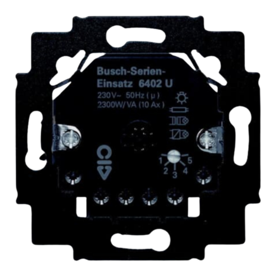
Universal-Serien-Einsatz
6402U-500
für Bedienelemente 6430-..., 6543-...,
6066-... und 6067-...
für Busch-Wächter
6810-xxx-10x-500, 6800-xxx-10x(M)-500,
Busch-Wächter
D
F
Betriebsanleitung
Nur für autorisiertes Elektrofachpersonal
180 UP-Sensoren
®
Präsenz 6813-xxx-500
®
GB
NL
0273 -1- 6292
I
E
28012
PL
RUS
Publicidad
Capítulos
Tabla de contenido

Manuales relacionados para ABB 6402U-500


Resumen de contenidos para ABB 6402U-500
- Página 1 0273 -1- 6292 28012 Universal-Serien-Einsatz 6402U-500 für Bedienelemente 6430-…, 6543-…, 6066-… und 6067-… für Busch-Wächter 180 UP-Sensoren ® 6810-xxx-10x-500, 6800-xxx-10x(M)-500, Busch-Wächter Präsenz 6813-xxx-500 ® Betriebsanleitung Nur für autorisiertes Elektrofachpersonal...
-
Página 2: Tabla De Contenido
Inhaltsverzeichnis Abbildungen - Fig. 1: Anschlussbeispiel (Normalbetrieb) ....4 - Fig. 2: Anschlussbeispiel (Betriebsarten 2 - 5) ..5 - Fig. 3 und 4: IR-Erfassungsbereich ......6 1. Überblick - Einsatzgebiete ............8 - Kombinationsmöglichkeiten ........8 2. Wichtige Hinweise - Dokumentation ............ - Página 3 Inhaltsverzeichnis 5. Bedienung - … mit Bedienelement 6430-…/6543-… ....20 - … mit IR-Bedienelement 6066-…/6067-… .... 20 - … mit Busch-Ferncontrol IR ......... 22 ® - … mit Sensoren ............. 23 - Nebenstellenbetrieb mit Sensoren ......23 - Passiver Nebenstellenbetrieb ......24 - Aktiver Nebenstellenbetrieb ........
-
Página 4: Fig. 1: Anschlussbeispiel (Normalbetrieb)
Fig. 1/Normalbetrieb Universal-Serien-Einsatz in der Betriebsart 1 (siehe Kap. 4.4) in Einzelbetrieb mit Tasteransteuerung Taster/ Taster/ Schließer 6402 U-500 Schließer HINWEIS Bei beleuchteten Tastern können ausschließlich Taster mit separatem N-Anschluss verwendet werden. Eine kontakt- parallele Beleuchtung ist nicht zulässig! -
Página 5: Fig. 2: Anschlussbeispiel (Betriebsarten 2 - 5)
Fig. 2 Universal-Serien-Einsatz in den Betriebsarten 2 - 5 (siehe Kap. 4.4) Lüfter Taster/ Schließer 6402 U-500... -
Página 6: Fig. 3 Und 4: Ir-Erfassungsbereich
Fig. 3 IR-Empfangsbereich – ~ 15 m –... - Página 7 Fig. 4 IR-Empfangsbereich 0° - 30° + 30° - 60° + 60° - 90° + 90° 100% 60% 20% 20% 60% 100% 0° + 30° - 30° + 60° - 60° + 90° - 90° 100% 60% 20% 20% 60% 100%...
-
Página 8: Überblick
Überblick 1.1 Einsatzgebiete Der Universal-Serien-Einsatz 6402U-500 (im folgenden Einsatz 6402 U-500) ist ein mit Nebenstelleneingängen bedienbarer Schalter zum Schalten von - Glühlampen - Halogenlampen - Niedervolt-Halogenlampen mit Transformator und - Leuchtstofflampen - Motoren 1.2 Kombinationsmöglichkeiten Der Einsatz 6402 U-500 ermöglicht u. a. den Betrieb der folgenden ABB Produkte: - IR-Bedienelement *6066-…, *6067-…... - Página 9 Überblick - UP-Sensoren Komfort 6800-xxx-102(M)/103M/104(M)-500 - Busch-Wächter Präsenz 6813-xxx-500 ® * Die Auswahl der Bedienelemente hängt nur von der entsprechenden Bedruckung ab, die Funktion ist je- weils identisch.
-
Página 10: Wichtige Hinweise
Typenzuordnung in der Beschreibung. Die Typenbezeichnung finden Sie auf der jeweiligen Geräte- rückseite. 2.2 Entsorgung Alle Verpackungsmaterialien und Geräte von ABB sind mit Kennzeichnungen und Prüfsiegel für die sach- und fachge- rechte Entsorgung ausgestattet. Entsorgen Sie Verpak- kungsmaterialien und Elektrogeräte bzw. deren Elektro- nikkomponenten über hierzu autorisierte Sammelstellen... -
Página 11: Technische Daten
Technische Daten 230 V ~ ± 10 % , 50 Hz Netzspannung: Leistungsaufnahme: < 1,5 W max. Schaltspannung: 250 V ~ max. Schaltstrom (für alle Ausgänge gemeinsam): 2300 W/ VA , 10 AX max. Brummspannung 100 V bei 100 m Leitungs- an der Nebenstelle: länge Tasteranzahl:... -
Página 12: Montage
Montage Netzspannung ausschalten! 4.1 Einbau des Einsatzes 6402 U-500 Der Einsatz 6402U-500 wird in eine handelsübliche UP- Gerätedose nach DIN 49073 Teil 1 montiert. 4.2.1 Montage in Verbindung mit Bedienelementen Montageort (siehe Fig. 3 und 4) In Kombination mit den IR-Bedienelementen 6066-… und 6067-…... -
Página 13: In Verbindung Mit Präsenz 6813-Xxx-500
Anbringen des Präsenzmelders 6813-xxx-500 Für die Installation und den Testbetrieb ist es sinnvoll, den beigelegten Adapter zu nutzen. Anschließend wird der Präsenzmelder 6813-xxx-500 auf den Einsatz 6402U-500 fest aufgerastet. Abnehmen des Präsenzmelders 6813-xxx-500 Ziehen Sie den Präsenzmelder 6813-xxx-500 am Gehäuse- ring vom Einsatz 6402U-500 ab. - Página 14 Montage • Die maximale Leitungslänge ist abhängig von der maxi- mal zulässigen Brummspannung an den Nebenstellen- eingängen. Die Brummspannung darf jedoch 100 V nicht überschreiten (das entspricht in der Praxis mindestens 100 m Leitungslänge). Als Nebenstellen kommen in Frage: - Schließertaster (z.B. 2020 US oder 2021/6 UK) ACHTUNG Die Beleuchtung der Tasternebenstelle parallel zum Schaltkontakt ist nicht zulässig: Taster mit separatem...
-
Página 15: In Verbindung Mit Up-Sensoren
Montage 4.2.4 ... in Verbindung mit UP-Sensoren/Präsenzmelder Um die optimale Funktion der UP-Sensoren zu gewährlei- sten, beachten Sie bitte die folgende Tabelle. UP-Sensor Typ / Montagehöhe Einbaulage der Präsenzmelder Einsatzgebiet Anschlussschrauben 6810-xxx-10x-500 0,8 - 1,2 m unten 6800-xxx-10x-500 6800-7x-10xM-500 0,8 - 1,2 m (Treppenhaus) oben 2,0 - 2,5 m... -
Página 16: Adressierung Des Ir-Bedienelementes/ Fig. 5
Montage/Fig. 5 Weitere Informationen zu Montagehöhe, Einstellung der UP-Sensoren, etc. entnehmen Sie bitte der zugehörigen Betriebsanleitung. 4.3 Adressierung des IR-Bedienelementes Die Adresse des IR-Bedienelementes 6066-…/6067-… ist werksseitig auf die Zahl 1 eingestellt. Eine Änderung der Adresse können Sie über das Adressrad auf der Rückseite des Bedienelementes vornehmen. - Página 17 Montage Die eingestellte Adresse gilt für Ausgang K1; die nächst höhere Adresse gilt automatisch für den zweiten Ausgang Tastennummern 6010-25 für die Ansteuerung der Einstellung Ausgänge (6402 U-500) 6066-/6067-xxx 6010-25 weiß blau...
-
Página 18: Betriebsarten
Montage 4.4 Betriebsarten Stellen Sie die gewünschte Betriebsart bitte vor Aufsetzen des Bedienelementes am Potentio- meter ein. Betriebsart 1 (Normalbetrieb): Separates Schalten beider Ausgänge mit den Bedienele- menten 6430-…, 6543-…, 6066-…, 6067-… Betriebsarten 2 - 5: Betriebsart Ausgang K1 EIN Ausgang K1 AUS Ausgang K2 Ausgang K2... - Página 19 Montage HINWEISE Ausgang K2 ist abhängig von Ausgang K1 – außer in der Betriebsart 1 (linker Endanschlag, siehe Fig. 1, 2). Wird Ausgang K1 innerhalb der Einschaltverzögerung von Ausgang K2 wieder ausgegeschaltet, so schaltet Ausgang K2 nicht ein.
-
Página 20: Bedienung
Bedienung Der Einsatz 6402U-500 erkennt beim Aufstecken des Bedienelementes automatisch, um welche Art von Bedienelement es sich handelt. 5.1 Mechanisches Bedienelement 6430-…/6543-… Einflächenbedienung in den Betriebsarten 2 - 5 • Fläche: Antippen/halten - EIN/AUS von Ausgang K1 Ausgang K2 schaltet entsprechend der gewählten Be- triebsart (siehe Kap. - Página 21 Bedienung Ausgang K2 schaltet entsprechend der gewählten Be- triebsart (siehe Kap. 4.4). HINWEISE Der Befehl „Dunkeldimmen“ über die IR-Fernbedienung löst im Einsatz 6402 U-500 keinen Schaltvorgang aus. Nähere Informationen zum IR-Betrieb entnehmen Sie bitte z. B. der Betriebsanleitung des IR-Handsenders. Die jeweils letzte Bedienung (auch an Nebenstellen) löst den Schaltvorgang aus, auch wenn bei längerem Halten der Bedienfläche die Bedienung noch nicht abgeschlossen...
-
Página 22: Mit Busch-Ferncontrol ® Ir
Bedienung 5.3 Busch-Ferncontrol IR-Betrieb ® a. Betriebsart 1: Der Zugriff auf die MEMO Speicher M1 und M2 erfolgt über den IR-Hand- bzw. Wandsender - siehe zugehörige Bedienungsanleitungen. • EIN-Schalten: Einsatz 6402 U-500 schaltet EIN* • AUS-Schalten: Einsatz 6402 U-500 schaltet AUS* •... -
Página 23: Mit Sensoren
Bedienung 5.4. Betrieb mit Sensoren (Betriebsarten 2 - 5) Nach Unterbrechung der Netzspannung oder Netzzu- schaltung schaltet der Einsatz 6402U-500 die angeschlos- senen Verbraucher Ausgang K1. - unabhängig von der gemessenen Helligkeit - beim Einsatz der UP-Sensoren 6810-xxx-10x-500 für 80 Sekunden wieder ein. -
Página 24: Passiver Nebenstellenbetrieb
Bedienung Passiver Nebenstellenbetrieb mittels Taster Die am Schließertaster ausgeführte Funktion bewirkt, dass die angeschlossenen Verbraucher a. in der Betriebsart 1 EIN und AUS geschaltet werden b. in der Betriebsart 2 - 5 - unabhängig von der gemessenen Helligkeit (Aus- gang K1) - beim Einsatz der UP-Sensoren 6810-xxx-10x-500 für ca. -
Página 25: Aktiver Nebenstellenbetrieb
Bedienung - Um Störungen durch Brummspannung zu vermeiden, ist die geschaltete Leitung getrennt von der Nebenstellen- leitung zu verlegen. Aktiver Nebenstellenbetrieb mit 6805 U-500 und UP- Sensoren (Betriebsart 2 - 5) Da Haupt- und Nebenstelle jeweils eine separate Einstel- lung des Dämmerungswertes besitzen, können die aktuel- len Helligkeitsverhältnisse am Einbauort individuell berück- sichtigt werden. -
Página 26: Mit Präsenz 6813-Xxx-500
Bedienung 5.6 Betrieb mit Busch-Wächter Präsenz 6813-xxx-500 ® Bitte beachten Sie die zugehörige Betriebsanleitung. Mit der Nebenstellenbedienung über Taster kann die Be- leuchtung helligkeitsunabhängig ein- bzw. ausgeschaltet werden. Die aktive Nebenstelle 6805 U-500 mit einem Präsenz- melder als Sensor bewirkt, dass die Bewegungserfassung an die Hauptstelle (Einsatz 6402 U-500 und 6813-xxx-500) weitergegeben wird. -
Página 27: Netzspannungsunterbrechung
Netzspannungsunterbrechung 6. Netzspannungsunterbrechung In Verbindung mit den Bedienelementen 6430-…, 6543-…, 6066-… und 6067-… wird der Schaltzustand bei Netz- spannungsunterbrechung < 200 ms wieder hergestellt. Bei einer Netzspannungsunterbrechung > 200 ms wird nach Netzspannungswiederkehr der alte Zustand wieder hergestellt oder beide Ausgänge sind AUS. In Verbindung mit Sensoren verhält sich der Einsatz 6402U- 500 wie unter Kapitel 5.4 beschrieben. -
Página 28: Störungsbeseitigung
Störungsbeseitigung Diagnose Ursache/Abhilfe Last schaltet nicht - Nebenstellen kontrollieren über Nebenstelle: - Brummspannung > 100 V reduzieren Last schaltet generell - defekte Last wechseln nicht: - ggf. Gerät wechseln Last schaltet selbst- - Brummspannung > 100 V ständig ein: reduzieren - falsche Leitungsverlegung beseitigen (s. - Página 29 Leuchtdiode der IR-C- - IR-Signalempfang prüfen Scheibe blinkt nicht - Batterie des IR-Hand- bzw. bei Sendesignal: Wandsenders erneuern - IR-Sendebereich überschritten Einsatz 6402U-500 - Beleuchtung in der Taster- läßt sich nicht über die Nebenstelle entfernen Nebenstelle bedienen: Keine Fernbedienung - Bedienelement klemmt möglich:...
- Página 30 Table des matières Figures - Fig. 1: Exemple de raccordement (fonctionnement normal) ........32 - Fig. 2: Exemple de raccordement (modes de fonctionnement 2 - 5) ......33 - Fig. 3 et 4: Zone de détection IR ......34 1. Vue d’ensemble - Domaines d’utilisation ...........
- Página 31 Table des matières 5. Commande - ... avec élément de commande 6430-... /6543-..48 - ... avec élément de commande IR 6066-... /6067-..49 - ... avec contrôle à distance Busch IR ..... 50 - ... avec sensors ............51 - Commande à...
-
Página 32: Fig. 1: Exemple De Raccordement (Fonctionnement Normal)
Fig. 1/Fonctionnement normal Insertion série universelle dans le mode de fonctionne- ment 1 (voir chapitre 4.4.) en fonctionnement individuel avec commande par boutons-poussoirs Contact de Contact de fermeture 6402 U-500 fermeture REMARQUE Dans le cas de boutons-poussoirs éclairés, seuls des boutons- poussoirs avec raccordement N séparé... -
Página 33: Fig. 2: Exemple De Raccordement (Modes De Fonctionnement 2 - 5)
Fig. 2 Insertion série universelle dans les modes de fonctionne- ment 2 - 5 (voir chapitre 4.4) Venti- lateur Contact fermeture 6402 U-500... -
Página 34: Fig. 3 Et 4: Zone De Détection Ir
Fig. 3 Zone de réception IR – ~ 15 m –... - Página 35 Fig. 4 Zone de réception IR 0° - 30° + 30° - 60° + 60° - 90° + 90° 100% 60% 20% 20% 60% 100% 0° + 30° - 30° + 60° - 60° + 90° - 90° 100% 60% 20% 20% 60% 100%...
-
Página 36: Vue D'ensemble - Domaines D'utilisation
- moteurs 1.2 Possibilités de combinaison L’insertion 6402 U-500 permet entre autres l’utilisation des produits ABB suivants: - élément de commande IR *6066-..., *6067-... - élément de commande *6430-..., *6543-... - contact de fermeture (par exemple art. n° : 2020 US ou 2021/6 UK) en cas de commande à... - Página 37 Vue d ’ensemble - sensors UP standard 6810-xxx-10x-500 - sensor UP confort 6800-xxx-102 (M)/103M/104(M)-500 - détecteur Busch "Präsenz" 6813-xxx-500 * La sélection des éléments de commande dépend uni- quement de l’impression correspondante, la fonction étant chaque fois identique.
-
Página 38: Remarques Importantes
Vous trouverez la désignation des types à la face arrière de l’appareil respectif. 2.2 Dépollution Tous les matériaux d’emballage et appareils de ABB sont munis de marquages et de cachets de contrôle permettant une dépollution dans les règles de l’art. Emportez les matériaux d’emballage et appareils électriques et/ou leurs... -
Página 39: Données Techniques
Données techniques 230 V C.A., ± 10 %, 50 Hz Tension de réseau: Puissance absorbée: < 1,5 W Tension d’enclenchement max.: 250 V C.A. Courant d’enclenchement max. (pour toutes les sorties): 2300 W/ VA, 10 AX Tension d’ondulation max. au niveau du poste 100 V pour une longueur supplémentaire: de ligne de 100 m... -
Página 40: Montage
Montage Mise hors circuit de la tension de réseau ! 4.1 Montage de l’insertion 6402U-500 L’insertion 6402 U-500 est montée dans une boîte UP de type commercial conformément à DIN 49073 partie 1. 4.2.1 Mont. en rapport avec des éléments de commande Lieu de montage (voir Fig. -
Página 41: En Rapport Avec "Präsenz" 6813-Xxx-500
Mise en place de l’avertisseur de présence 6813-xxx-500 Pour l’installation et le fonctionnement d’essai, il est recom- mandé de se servir d’un adaptateur. Puis l’avertisseur de présence 6813-xxx-500 est fixé sur l’insertion 6402U-500. Enlèvement de l’avertisseur de présence 6813-xxx-500 Enlevez l’avertisseur de présence 6813-xxx-500 de l’inser- tion 6402 U-500 au niveau de l’anneau du boîtier. - Página 42 Montage • La longueur de ligne maximum est fonction de la tension d’ondulation maximum autorisée au niveau des postes supplémentaires. La tension d’ondulation ne devrait toutefois pas dépasser 100 V (cela correspond en prati- que à une longueur de ligne d’au moins 100 m). En tant que postes supplémentaires entrent en ligne de compte: - Contacts de fermeture (par ex.
-
Página 43: En Rapport Avec Des Sensors Up
Montage 4.2.4 ...en rapport avec des sensors UP/avertisseur de présence Pour garantir le fonctionnement optimal des sensors UP, veuillez tenir compte du tableau suivant. Type sensor UP/ Hauteur de montage Position de mon- Avertisseur Domaine d’utilisation tage des vis de de présence raccordement 6810-xxx-10x-500 0,8 - 1,2 m... -
Página 44: Adressage De L'élément De Commande Ir/Fig. 5
Montage/Fig. 5 Vous trouverez dans les instructions de service respecti- ves d’autres informations concernant la hauteur de mon- tage, le réglage des sensors UP, etc. 4.3 Adressage de l’élément de commande IR L’adresse de l’élément de commande IR 6066-.../6067-... est réglée par l’usine sur le chiffre 1. Vous pouvez procéder à... - Página 45 Montage L’adresse indexée s’applique à la sortie K1; l’adresse juste au-dessus s’applique automatiquement à la deuxième sor- tie K2. Numéros de boutons- poussoirs 6010-25 pour la commande des sorties Réglage (6402 U-500) 6066-/6067-xxx 6010-25 blanc bleu...
- Página 46 Montage 4.4 Modes de fonctionnement Avant de poser l’élément de commande, réglez le mode de fonctionnement souhaité au niveau du potentiomètre. Mode de fonctionnement 1 (fonctionnement normal) Commutation séparée des deux sorties avec les éléments de commande 6430-..., 6543-..., 6066-..., 6067-... Modes de fonctionnement 2 - 5: Mode de Sortie K1 MARCHE...
- Página 47 Montage REMARQUE La sortie K2 est fonction de la sortie K1 – sauf dans le mode de fonctionnement 1 (butée de fin de course gauche, voir Fig. 1, 2). Si la sortie K1 est de nouveau mise hors circuit pendant la temporisation de mise en circuit de la sortie K2, la sortie K2 ne commute pas.
-
Página 48: Commande
Commande Lors de la fixation de l’élément de commande, l’insertion 6402 U-500 reconnaît automatiquement de quel type d’élé- ment de commande il s’agit. 5.1 Elément de commande mécanique 6430-.../6543-... Commande d’une surface dans les modes de fonction- nement 2 - 5 •... -
Página 49: Avec Élément De Commande Ir 6066
REMARQUES L’ordre "variation sur plus foncé" par l’intermédiaire de la commande à distance IR ne déclenche pas de processus de commutation dans l’insertion 6402U-500. Vous trouverez des informations plus détaillées sur le fonctionnement IR par exemple dans les instructions de service de l’émetteur manuel IR. -
Página 50: Avec Contrôle À Distance Busch Ir
– voir ins- tructions de service respectives. • MISE EN CIRCUIT: L’insertion 6402U-500 se met EN CIRCUIT * • MISE HORS CIRCUIT: L’insertiion 6402U-500 se met HORS CIRCUIT * • Plus clair: L’insertion 6402U-500 se met EN CIRCUIT * •... -
Página 51: Avec Sensors
5.4 Fonctionnement avec sensors (modes de fonction- nement 2 - 5) Après interruption de la tension de réseau ou de la mise en circuit, l’insertion 6402U-500 remet en circuit les consom- mateurs raccordés sortie K1 - indépendamment de la luminosité mesurée - pour 80 secondes lors de l’utilisation des sensors UP... -
Página 52: Commande À Postes Supplémentaires Avec Sensors
Commande 5.5 Commande à postes supplémentaires avec sensors (modes de fonctionnement 2 - 5) Cette commande à postes supplémentaires n’agit que sur la sortie K1. La sortie K2 commute conformément au mode de fonctionnement indexé (voir chapitre 4.4). La com- mande à... - Página 53 Commande pour des réglages de temporisation inférieurs à 1 minute) - sont commutés lors de l’utilisation du détecteur Busch "Präsenz" 6813-xxx-500 (MARCHE > ARRET > MAR- CHE >...). REMARQUES - Dans le cas d’une commande à postes supplémentaires au moyen d’un contact de fermeture, la longueur maxi- mum de la ligne de poste supplémentaire ne doit pas dépasser 100 m.
-
Página 54: Commande Active À Postes Supplémentaires
Commande laire, les rapports actuels de luminosité sur le lieu de montage peuvent être pris en considération de façon individuelle. La durée de temporisation effective résulte de l’addition des durées au poste principal et au poste supplémentaire. En rapport avec les sensors UP 6800-xxx-10x(M)-500, il est recommandé... -
Página 55: Avec "Präsenz" 6813-Xxx-500
Commande 5.6 Fonctionnement avec le détecteur Busch "Präsenz" 6813-xxx-500 Veuillez tenir compte des instructions de service respecti- ves. Avec la commande à postes supplémentaires par l’inter- médiaire de boutons-poussoirs, l’éclairage peut être mis en et/ou hors circuit indépendamment de la luminosité. Le poste supplémentaire actif 6805U-500 avec un avertis- seur de présence en tant que sensor fait que la détection de mouvement est transmise au poste principal (insertion... -
Página 56: Interruption De La Tension De Réseau
Interruption de la tension de réseau 6. Interruption de la tension de réseau En rapport avec les éléments de commande 6430-..., 6543- ..., 6066-... et 6067-..., l’état de commutation est de nou- veau rétabli dans le cas d’une interruption de la tension de réseau <... -
Página 57: Elimination Des Perturbations
Aide en cas de pannes Diagnostic Cause/Remède La charge ne commute - Contrôler les postes supplé- pas par l’intermédiaire mentaires d’un poste - Réduire la tension d’ondula- supplémentaire: tion > 100 V La charge ne commute - Remplacer la charge généralement pas: défectueuse - Le cas échéant, remplacer... -
Página 58: Aide En Cas De Pannes
Aide en cas de pannes Diode lumineuse de la - Eliminer la source de lumière plaque IR-C éteinte: parasite IR - Appliquer la tension de réseau - Mettre la tension de réseau hors circuit pour 5 secondes environ La diode lumineuse de - Eliminer la source de lumière la plaque IR-C clignote parasite IR en permanence:... - Página 59 Aide en cas de pannes Diagnostic Cause/Remède Pas de commande à - L’élément de commande distance possible: coince La lumière ne brûle pas: - Remplacer la lampe défectueuse - Remplacer/remettre en circuit le fusible placé en amont - Remettre en état la conduite d’alimentation interrompue - Vérifier/le cas échéant chan- ger le mode de fonctionne-...
- Página 60 Table of Contents Figures - Fig. 1: Wiring example (Normal Mode) ....62 - Fig. 2: Wiring example (Modes of Operation) ..63 - Fig. 3 and 4: IR Receiving Range ......64 1. Overview - Fields of Application ..........66 - Possible Combinations ..........
- Página 61 Table of Contents 5. Operation - ... via Operating Element 6430-... /6543-....78 - ... via IR Operating Element 6066-... /6067-... 78 - ... via Busch Remote Control ......... 80 - ... via Sensors ............81 - ... Extension Operation via Sensors ....... 81 - ...
-
Página 62: Fig. 1: Wiring Example (Normal Mode)
Fig. 1/Normal Mode Universal Series Insert in Operating Mode 1 (see Chapter 4.4) in individual mode with pushbutton control NO-contact NO-contact pushbutton 6402 U-500 pushbutton NOTE In the case of illuminated pushbuttons, only pushbuttons with a separate N terminal can be used. Illumination via parallel contacts is not permissible! -
Página 63: Fig. 2: Wiring Example (Modes Of Operation)
Fig. 2 Universal Series Insert in Operating Mode 2 (see Chapter 4.4) contact pushbutton 6402 U-500... -
Página 64: Fig. 3 And 4: Ir Receiving Range
Fig. 3 IR Receiving Range – ~ 15 m –... - Página 65 Fig. 4 IR Receiving Range 0° - 30° + 30° - 60° + 60° - 90° + 90° 100% 60% 20% 20% 60% 100% 0° + 30° - 30° + 60° - 60° + 90° - 90° 100% 60% 20% 20% 60% 100%...
-
Página 66: Overview
- low-voltage halogen lamps with transformers, as well as - fluorescent lamps and - motors 1.2 Possible Combinations Insert 6402U-500 can be used, inter alia, to control the following ABB products: - IR Operating Element *6066-..., *6067-..., - Operating Element *6430-..., *6543-... - Página 67 Overview - FM Comfort Sensors 6800-xxx-102(M)/103M/104(M)- - Busch Watchdog Präsenz 6813-xxx-500 ® * The type of operating element chosen depends only on the appropriate lettering. Operation is always identical.
-
Página 68: Important Information
The type description is on the back of each device. 2.2 Waste Disposal All packaging materials and devices from ABB are provided with identification and test marks to ensure appropriate and proper disposal. Dispose of packaging materials, as... -
Página 69: Technical Data
Technical Data 230 V ~ ± 10 %, 50 Hz Supply voltage: Wattage: < 1.5 W Max. switching voltage: 250 V ~ Max. switched current (for all outputs together): 2300 W/ VA , 10 AX Max. ripple voltage 100 V with 100 m line at the extension: length No. -
Página 70: Installation - Installation
Installation Switch off supply voltage! 4.1 Installation of Insert 6402 U-500 Insert 6402U-500 is installed in a conventional FM device box in accordance with DIN 49073, Part 1. 4.2.1 Installation in conjunction with Operating Ele- ments Installation Site (see Fig. 3 and 4) When used in conjunction with IR Operating Elements 6066- ... -
Página 71: In Conjunction With Präsenz 6813-Xxx-500
To fit Presence Detector 6813-xxx-500 For installation and testing mode, it is recommendable to use the adapter provided. Subsequently, Presence Detec- tor 6813-xxx-500 is firmly clipped onto Insert 6402U-500. To remove Presence Detector 6813-xxx-500 Pull Presence Detector 6813-xxx-500 off Insert 6402U-500 by means of the ring on the housing. - Página 72 Installation • The maximum line length depends on the maximum permissible ripple voltage at the extension inputs. How- ever, the ripple voltage must not exceed 100 V (in practice, this corresponds to a line length of at least 100 m). The following can be used as an extension: - NO-contact pushbutton (e.g., 2020 US or 2021/6 UK) CAUTION...
- Página 73 Installation 4.2.4 ... in conjunction with FM Sensors/Presence De- tectors To ensure optimum operation of the FM sensors, refer to the following table. Type of FM Sensor/ Installation Height Installation loca- Presence Detector Field of Application tion of the con- necting screws 6810-xxx-10x-500 0,8 - 1,2 m...
-
Página 74: Addressing The Ir Operating Element/Fig. 5
Installation/Fig. 5 For further information regarding the installation height, setting of the FM sensors, etc., please refer to the appur- tenant Operating Instructions. 4.3 Addressing the IR Operating Element The address of the IR Operating Elements 6066-... and 6067-... is set ex Works to the number 1. The address can be changed via the rotary address disc on the back of the operating element. - Página 75 Installation The address set applies in respect of output K1; the next highest address automatically applies in respect of the second output, K2. Pushbutton numbers 6010-25 to control Setting the outputs (6402 U-500) 6066-/6067-xxx 6010-25 white blue...
-
Página 76: Modes Of Operation
Installation 4.4 Modes of Operation Set the operating mode desired prior to fitting the operating element on the potentiometer. Operating Mode 1 (Normal Mode): Separate switching of both outputs via the Operating Elements 6430-..., 6543-..., 6066-... and 6067-..Operating Modes 2 - 5: Operating Output K1 ON Output K1 OFF... - Página 77 Installation NOTE Output K2 is independent of Output K1, except in Operating Mode 1 (left limit stop, see Fig. 1 and 2). If Output K1 is switched off again during the switch-on delay period of Output K2, Output K2 is not switched on.
-
Página 78: Operation
Operation When the operating element is clipped on, Insert 6402 U- 500 automatically recognizes the type of operating ele- ment concerned. 5.1 Mechanical Operating Element 6430-.../6543-... Single-surface operation in Operating Modes 2 - 5 • Surface: Press/hold down - Output K1 ON/OFF Output K2 switches according to the operating mode selected (see Chapter 4.4) 5.2 IR Operating Element 6066-.../6067-... - Página 79 Operation Output K2 switches according to the operating mode selected (see Chapter 4.4) NOTE The command "Dim down" via the IR Remote Control does not initiate a switching operation. For further information regarding IR control, please refer, e.g., to the Operating Instructions of the IR Hand-held Transmitter.
-
Página 80: Via Busch Remote Control
Operation 5.3 Busch Remote Control IR Operation ‚ a. Operating Mode 1: The MEMO memories M1 and M2 are accessed via the IR Hand-held, or Wall-mounted Transmitter - see appurtenant Operating Instructions. • Switch ON: Insert 6402 U-500 switches ON * •... -
Página 81: Via Sensors
Operation 5.4 Operation via Sensors (Operating Modes 2 - 5) After interruption of the supply voltage or connection to the supply, Insert 6402 U-500 switches the connected con- sumers connected of Output K1 on again - irrespective of the brightness measured - for 80 seconds when FM Sensors 6810-xxx-10x-500 are used, - for the selected period (at least 1 minute with time-... -
Página 82: Passive Extension Operation
Operation Passive Extension Operation via Pushbutton The operation effected via the NO-contact pushbutton causes the connected consumers a. to be switched ON and OFF in Operating Mode 1 b. in Operating Modes 2 - 5, - irrespective of the brightness measured (Output K1), - to be switched on for approx. -
Página 83: Active Extension Operation
Operation - In order to prevent faults as a result of ripple voltage, the switched line is to be laid separate to the extension line. Active Extension Operation via 6805 U-500 and FM Sensors (Operating Modes 2 - 5) Since the master and extension each have a separate dusk- value setting, the current brightness conditions at the installation site must be taken into account individually. -
Página 84: Via Präsenz 6813-Xxx-500
Active Extension 6805 U-500, with a presence detector as sensor, ensures that the movements detected are trans- mitted to the master (Insert 6402U-500 and 6813-xxx-500). The master, Presence Detector 6813-xxx-500 decides, irrespective of the brightness, whether the lighting is to be/... -
Página 85: Supply Voltage Interruption
< 200 ms, the control state is restored. In case of a supply voltage interruption > 200 ms, the old state will be restored, or both outputs are OFF, when the supply voltage is restored. In conjuncton with sensors, Insert 6402U-500 behaves as described in Chapter 5.4. -
Página 86: Fault Elimination
Fault Elimination Diagnosis Cause/Remedy Load does not switch - Check extensions via extension: - Ripple voltage > 100 V, reduce Load does not generally - Defective load, replace switch: - Replace device if necessary Load switches on - Ripple voltage > 100 V, automatically: reduce - Line(s) laid incorrectly,... - Página 87 - Replace battery of IR Hand- transmitting signal: held, or Wall-mounted Transmitter - IR transmission range exceeded Insert 6402U-500 - Remove lighting from the cannot be controlled pushbutton extension via the extension: No remote control - Operating Element is jammed...
- Página 88 Inhoudsopgave Afbeeldingen - Fig. 1: Aansluitvoorbeeld (normaal bedrijf) .... 90 - Fig. 2: Aansluitvoorbeeld (modi 2 - 5) ....91 - Fig. 3 en 4: IR-detectiebereik ......... 92 1. Overzicht - Toepassingsgebieden ..........94 - Combinatiemogelijkheden ........94 2. Belangrijke aanwijzingen - Documentatie ............
- Página 89 Inhoudsopgave 5. Bediening - ... met bedieningselement 6430-.../6543-.... 106 - ... met bedieningselement 6066-.../6067-.... 106 - ... met Busch-Ferncontrol IR ......108 ® - ... met sensoren ..........109 - Nevenpostbedrijf met sensoren ......109 - Passief nevenpostbedrijf ........110 - Actief nevenpostbedrijf ........
- Página 90 Fig. 1/Normaal bedrijf Universele serie-inbouwsokkel in de modus 1 (zie hoofdstuk 4.4) in afzonderlijk bedrijf met impulsdrukkeraansturing impulsdrukker/ impulsdrukker/ met maakcontact 6402 U-500 met maakcontact AANWIJZING Bij verlichte impulsdrukkers kunnen uitsluitend impuls- drukkers met afzonderlijke N-aansluiting worden gebruikt. Een contactparallele verlichting is niet toegestaan!
- Página 91 Fig. 2 Universele serie-inbouwsokkel in de modi 2 - 5 (zie hoofd- stuk 4.4) venti- lator impuls- drukker/ met maak- contact 6402 U-500...
- Página 92 Fig. 3 IR-ontvangstbereik – ~ 15 m –...
- Página 93 Fig. 4 IR-ontvangstbereik 0° - 30° + 30° - 60° + 60° - 90° + 90° 100% 60% 20% 20% 60% 100% 0° + 30° - 30° + 60° - 60° + 90° - 90° 100% 60% 20% 20% 60% 100%...
-
Página 94: Overzicht
Overzicht 1.1 Toepassingsgebieden De universele serie-inbouwsokkel 6402 U-500 (hierna inbouwsokkel 6402U-500) is een met nevenpostingangen bedienbare schakelaar voor het schakelen van - gloeilampen - halogeenlampen - laagvolt-halogeenlampen met transformator en - TL-lampen - motoren 1.2 Combinatiemogelijkheden De inbouwsokkel 6402 U-500 maakt o.a. het gebruik van de volgende ABB producten mogelijk: - IR-bedieningselement *6066-..., *6067-... - Página 95 Overzicht - inbouwsensoren comfort 6800-xxx-102(M)/103M/104(M)-500 - Busch-Wächter presentiemelder 6813-xxx-500 ® * De keuze van de bedieningselementen is slechts afhan- kelijk van de overeenkomstige print. De functie is tel- kens identiek.
-
Página 96: Belangrijke Aanwijzingen
De type-aanduiding kunt u vinden op de betreffende ach- terkant van het apparaat. 2.2 Afvoer Alle verpakkingsmaterialen en apparaten van ABB zijn van markeringen en keuringszegels voor deskundige en vak- kundige afvoer voorzien. Lever het verpakkingsmateriaal en de elektrische toestellen resp. de elektronische compo- nenten ervan in bij de hiertoe erkende verzamelplaatsen resp. -
Página 97: Technische Gegevens
Technische gegevens 230 V ~ ± 10 %, 50 Hz Netspanning: Krachtontneming: < 1,5 W Max. schakelspanning: 250 V ~ Max. schakelstroom (voor alle uitgangen samen): 2300 W/ VA , 10 AX Max. rimpelspanning 100 V bij 100 m leidings- aan de nevenpost: lengte Aantal impulsdrukkers:... -
Página 98: Montage
Montage Netspanning uitschakelen! 4.1 Montage van de inbouwsokkel 6402U-500 De inbouwsokkel 6402U-500 wordt in een in de handel gebruikelijke inbouwdoos volgens DIN 49073 deel 1 inge- bouwd. 4.2.1 Montage in combinatie met bedieningselementen Montageplaats (zie Fig. 3 en 4) In combinatie met de IR-bedieningselementen 6066-... en 6067-... -
Página 99: In Combinatie Met Nevenposten
Voor de installatie en het testbedrijf is het zinvol van de bijgevoegde adapter gebruik te maken. Vervolgens wordt de presentiemelder 6813-xxx-500 op de inbouwsokkel 6402U-500 vastgezet. Afnemen van de presentiemelder 6813-xxx-500 Trek de presentiemelder 6813-xxx-500 bij de kastring van de inbouwsokkel 6402 U-500 af. - Página 100 Montage • De maximale leidingslengte is afhankelijk van de maxi- maal toelaatbare rimpelspannning op de nevenpost- ingangen. De rimpelspanning mag echter 100 V niet te boven gaan (dit stemt in de praktijk overeen met een leidingslengte vanaf 100 m). Als nevenposten komen in aanmerking: - impulsdrukker met maakcontact (bijv.
-
Página 101: In Combinatie Met Inbouwsensoren
Montage 4.2.4 ... in combinatie met inbouwsensoren/presentie- melder Om de optimale functie van de inbouwsensoren te garan- deren op de volgende tabel letten a.u.b. Inbouwsensor type/ Montagehoogte Inbouwpositie van presentiemelder toepassings- de aansluit gebied schroeven 6810-xxx-10x-500 0,8 - 1,2 m beneden 6800-xxx-10x-500 6800-7x-10xM-500 0,8 - 1,2 m... -
Página 102: Adressering Van Het Ir-Bedieningselement/Fig
Montage/Fig. 5 Nadere informatie over montagehoogte, instelling van de inbouwsensoren enz. kunt u opmaken uit de bijbehorende gebruiksaanwijzing. 4.3 Adressering van het IR-bedieningselement Het adres van het IR-bedieningselement 6066-.../6067-... is door de fabriek ingesteld op het getal 1. Het adres kunt u via het adreswieltje op de achterkant van het bedienings- element wijzigen. - Página 103 Montage Het ingestelde adres is van toepassing voor uitgang K1, het adres onmiddellijk erboven is automatisch van toepassing voor de tweede uitgang K2. Impulsdrukkernummers 6010-25 voor de aan- sturing van de uitgangen Instelling (6402 U-500) 6066-/6067-xxx 6010-25 blauw...
-
Página 104: Modi
Montage 4.4 Modi Stel de gewenste modus voor het plaatsen van het bedieningselement op de potentiometer in. Modus 1 (normaal bedrijf): Afzonderlijk schakelen van beide uitgangen met de bedieningselementen 6430-..., 6543-..., 6066-..., 6067-... Modi 2 - 5: Modus Uitgang K1 AAN Uitgang K1 UIT uitgang K2 uitgang K2... - Página 105 Montage AANWIJZINGEN Uitgang K2 is afhankelijk van uitgang K1 – behalve in de modus 1 (linker eindaanslag, zie Fig. 1, 2). Indien uitgang K1 binnen de inschakelvertraging van uitgang K2 weer wordt uitgeschakeld, dan schakelt uitgang K2 niet in.
-
Página 106: Bediening
Bediening De inbouwsokkel 6402U-500 herkent bij het opsteken van het bedieningselement automatisch om welk soort bedieningselement het gaat. 5.1 Mechanisch bedieningselement 6430-.../6543-... Éénvlakbediening in de modi 2 - 5 • Bovenste vlak: Aantippen/vasthouden - AAN/UIT van uitgang K1 Uitgang K2 schakelt overeenkomstig de gekozen modus (zie hoofdstuk 4.4). - Página 107 Bediening Uitgang K2 schakelt overeenkomstig de gekozen modus (zie hoofdstuk 4.4). AANWIJZINGEN De opdracht "donkerder dimmen" via de IR-afstandsbedie- ning activeert in de inbouwsokkel 6402 U-500 geen schakel- proces. Nadere informatie over IR-bedrijf kunt u bijv. opmaken uit de gebruiksaanwijzing van de IR-handzender. De telkens laatste bediening (ook op nevenposten) acti- veert het schakelproces, ook als bij langer vasthouden van het bedieningsvlak de bediening nog niet afgesloten blijkt.
-
Página 108: Met Busch-Ferncontrol ® Ir
De toegang naar het MEMO geheugen M1 en M2 ge- schiedt via de IR-hand- resp. wandzender - zie bijbehorende gebruiksaanwijzingen. • IN-schakelen: Inbouwsokkel 6402U-500 schakelt IN* • UIT-schakelen: Inbouwsokkel 6402U-500 schakelt UIT* • Lichter: Inbouwsokkel 6402U-500 schakelt IN* • Donkerder: Geen functie •... -
Página 109: Met Sensoren
Bediening 5.4 Bedrijf met sensoren (modi 2 - 5) Na onderbreking van de netspanning of netbijschakeling schakelt de inbouwsokkel 6402 U-500 de aangesloten ver- bruikers uitgang K1 - onafhankelijk van de gemeten helderheid - bij het gebruik van de inbouwsensoren 6810-xxx-10x- 500 voor 80 seconden weer in, - bij het gebruik van de inbouwsensoren 6800-xxx-10x(M)- 500 of de Busch-Wächter... -
Página 110: Passief Nevenpostbedrijf
Bediening Passief bedrijf van een nevenpost door middel van impulsdrukker De aan de impulsdrukker met maakcontact uitgevoerde functie zorgt ervoor dat de aangesloten verbruikers a. in de modus 1 IN- en UIT-geschakeld worden b. in de modus 2 - 5 - onafhankelijk van de gemeten helderheid (uitgang K1) - bij het gebruik van de inbouwsensoren 6810-xxx-10x- 500 voor ca. -
Página 111: Actief Nevenpostbedrijf
Bediening - Gebruik a.u.b . uitsluitend impulsdrukkers zonder contactparallelle verlichting. - Om storingen door rimpelspanning te voorkomen, dient de geschakelde leiding gescheiden van de leiding van de nevenpost te worden gelegd. Actief nevenpostbedrijf met 6805U-500 en inbouw- sensoren (modus 2 - 5) Omdat de hoofd- en nevenpost telkens een afzonderlijke instelling van de schemerwaarde bezitten kan met de actuele lichtomstandigheden bij de montageplaats apart... -
Página 112: Met Presentiemelder 6813-Xxx-500
De actieve nevenpost 6805U-500 met een presentiemelder als sensor zorgt ervoor dat de bewegingsdetectie naar de hoofdaansluiting (inbouwsokkel 6402U-500 en 6813-xxx-500) wordt doorgegeven. De hoofdaansluiting presentiemelder 6813-xxx-500 beslist afhankelijk van de helderheid of de verlichting ingeschakeld wordt/blijft. -
Página 113: Netspanningsonderbreking
Netspanningsonderbreking 6. Netspanningsonderbreking In combinatie met de bedieningselementen 6430-..., 6543- ..., 6066-... en 6067-... wordt de schakeltoestand bij net- spanningsonderbreking < 200 ms weer tot stand gebracht. Bij een netspanningsonderbreking > 200 ms wordt na terugkeren van de netspanning de oude toestand weer tot stand gebracht of beide uitgangen zijn UIT. -
Página 114: Hulp Bij Storing
Hulp bij storing Diagnose Oorzaak/oplossing Belasting schakelt niet - Nevenposten controleren via nevenpost: - Rimpelspanning > 100 V reduceren Belasting schakelt in - Defecte belasting vervangen het algemeen niet: - Zo nodig apparaat vervangen Belasting schakelt zelf- - Rimpelspanning > 100 V standig in: reduceren - Verkeerd gelegde leiding... - Página 115 Lichtdiode van de IR-C- - IR-signaalontvangst controleren schijf knippert niet - Batterij van de IR-hand resp. bij zendersignaal: wandzender vervangen - IR-zendbereik overschreden. Inbouwsokkel 6402U-500 - Verlichting in de impuls- kan niet via de neven- drukker-nevenpost verwijderen. post worden bediend: Geen afstandsbedie- - Bedieningselement zit vast...
- Página 116 Indice Figure - Fig.1: esempio di collegamento (funzionamento normale) ........118 - Fig.2: esempio di collegamento (modalità di funzionamento 2 - 5) ......119 - Fig.3 e 4: zona di rilevamento infrarossi ....120 1. Sommario - Campi d’impiego ..........122 - Possibilità...
- Página 117 Indice - Indirizzamento dell’elemento di comando a infrarossi /Fig.5 ............ 130 - Modalità di funzionamento ........132 5. Impiego - …con elemento di comando 6430-…/6543-..134 - …con elemento di comando a infrarossi 6066-…/6067-............134 - …con telecomando Busch a infrarossi ....
- Página 118 Fig. 1/Funzionamento normale Inserto in serie universale nella modalità di funzionamento 1 (vedi cap. 4.4), nel funzionamento singolo con comando a tasti tasto/contatto tasto/contat- 6402 U-500 di chiusura to di chiusura AVVERTENZA Con tasti luminosi si possono utilizzare esclusivamente tasti con collegamento N separato. Non è ammessa l’illuminazione contatto-parallela!
- Página 119 Fig. 2 Inserto in serie universale nella modalità di funzionamento 2 - 5 (vedi cap. 4.4). venti- latore tasto/ contatto di chiusura 6402 U-500...
- Página 120 Fig. 3 Area di ricezione infrarossi – ~ 15 m –...
- Página 121 Fig. 4 Area di ricezione infrarossi 0° - 30° + 30° - 60° + 60° - 90° + 90° 100% 60% 20% 20% 60% 100% 0° + 30° - 30° + 60° - 60° + 90° - 90° 100% 60% 20% 20% 60% 100%...
-
Página 122: Sommario
Sommario 1.1 Campi d’impiego L’inserto in serie universale 6402 U-500 (di seguito denomi- nato inserto 6402U-500) è un interruttore azionabile con entrate di apparecchi derivati per il comando di - lampade ad incandescenza - lampade alogene - lampade alogene a basso voltaggio con trasformatore e... - Página 123 Sommario - sensori UP comfort 6800-xxx-102(M)/103M/104(M)- - controllo automatico Busch Präsenz 6813-xxx-500 ® * La scelta degli elementi di comando dipende solo dalla sovrastampa corrispondente; la funzione è sempre la stessa.
-
Página 124: Avvertenze Importanti
La denominazione di tipo si trova sul lato posteriore del relativo apparecchio. 2.2 Smaltimento Tutti i materiali di imballaggio e gli apparecchi di ABB sono provvisti di contrassegni e sigilli per consentire uno smaltimento corretto. Eliminate i materiali d’imballaggio e gli apparecchi elettrici o i loro componenti elettronici trami- te punto di raccolta o imprese di smaltimento autorizzate. -
Página 125: Dati Tecnici
Dati tecnici 230 V ~ ± 10 %, 50 Hz Tensione di rete: Potenza assorbita: < 1,5W Tensione di comando massima: 250 V ~ Corrente di comando massima (per tutte le uscite complessivamente): 2300 W/ VA , 10 AX Tensione di ronzio massima 100 V per 100 m di sull’apparecchio derivato: lunghezza del cavo Numero di tasti:... -
Página 126: Montaggio
(per es. luce solare, illuminazione). Applicazione dell’elemento di comando Con elemento di comando a infrarossi 6066-…/6067-… impostare dapprima l’indirizzo desiderato. Inserire l’ele- mento di comando sull’inserto 6402U-500. Estrazione dell’elemento di comando Per l’estrazione utilizzare gli intagli predisposti a destra e a sinistra. -
Página 127: In Combinazione Con Präsenz 6813-Xxx-500
Montaggio 4.2.2 Montaggio in combinazione con il controllo auto- matico Busch Präsenz 6813-xxx-500 ® Luogo di montaggio In combinazione con il segnalatore di presenza 6813-xxx- 500 è utile solo un’installazione a soffitto. Se possibile il segnalatore 6813-xxx-500 andrebbe montato proprio sopra il relativo posto di lavoro. - Página 128 Montaggio • La lunghezza massima del cavo dipende dalla massima tensione di ronzio consentita sulle entrate degli apparec- chi derivati. La tensione di ronzio non può comunque superare i 100 V (che corrispondono solitamente ad una lunghezza del cavo di almeno 100 m). Gli apparecchi derivati adatti sono: - tasti per contatto di chiusura (per es.
-
Página 129: In Combinazione Con Sensori Up
Montaggio 4.2.4…in combinazione con sensori UP/segnalatori di presenza Per assicurare un funzionamento ottimale dei sensori UP, osservare la seguente tabella. Tipo di sensore UP/ Altezza di Posizione di mon- Segnalatore di montaggio taggio delle viti di presenza Campo d’impiego collegamento 6810-xxx-10x-500 0,8 - 1,2 m sotto 6800-xxx-10x-500... -
Página 130: Indirizzamento Dell'elemento Di Comando A Infrarossi /Fig.5
Montaggio/Fig. 5 Per ulteriori informazioni sull’altezza di montaggio, la regolazione dei sensori UP, ecc. vedere le relative istruzioni d’uso. 4.3 Indirizzamento dell’elemento di comando a infra- rossi L’indirizzo dell’elemento di comando a infrarossi 6066-…/ 6067-… è impostato in fabbrica sul numero 1. È possibile modificare l’indirizzo per mezzo della rotella di regolazione posta sul lato posteriore dell’elemento di comando. - Página 131 Montaggio L’indirizzo impostato vale per l’uscita K1; l’indirizzo succes- sivo più alto vale automaticamente per la seconda uscita Numeri dei tasti 6010-25 per il comando delle Regolazione uscite (6402U-500) 6066-/6067-xxx 6010-25 bianco...
-
Página 132: Modalità Di Funzionamento
Montaggio 4.4 Modalità di funzionamento Si raccomanda di impostare sul potenziometro la modalità di funzionamento desiderata prima di inserire l’elemento di comando. Modalità di funzionamento 1 (funzionamento normale): collegamento separato delle due uscite con gli elementi di comando 6430-…, 6543-…, 6066-…, 6067-… Modalità... - Página 133 Montaggio AVVERTENZE L’uscita K2 dipende dall’uscita K1 – eccetto che nella modalità di funzionamento 1 (finecorsa sinistro, vedi Fig. 1, 2). Se l’uscita K1 viene di nuovo disinserita all’interno del ritardo d’inserzione dell’uscita K2, quest’ultima non si inserisce.
-
Página 134: Con Elemento Di Comando 6430
Impiego Con l’installazione dell’elemento di comando, l’inserto 6402 U-500 riconosce automaticamente di quale tipo di elemento si tratta. 5.1 Elemento di comando meccanico 6430-…/6543-… Comando ad un pulsante nelle modalità operative 2 - 5 • pulsante: battuta/pressione - ON/OFF dell’uscita K1 L’uscita K2 comanda conformemente alla modalità... - Página 135 Impiego L’uscita K2 comanda conformemente alla modalità opera- tiva selezionata (vedi cap. 4.4). AVVERTENZE Il comando di "oscuramento" attraverso telecomando a infrarossi non attiva alcuna commutazione nell’inserto 6402 U-500. Ulteriori informazioni per il funzionamento a infrarossi si trovano per esempio nelle istruzioni d’uso del teleco- mando.
-
Página 136: A Infrarossi
- creare il collegamento** - memorizzare MEMO - richiamare MEMO 1 o MEMO 2 • DISATTIVA TUTTO: l’inserto 6402U-500 si spegne** * Viene comandata l’uscita K1 o K2, a seconda della coppia di tasti che si aziona sul telecomando a infrarossi. -
Página 137: Con Sensori
5.4 Azionamento con sensori (modalità di funziona- mento 2 - 5) Dopo un’interruzione della tensione di rete o dell’allaccia- mento alla rete, l’inserto 6402U-500 inserisce di nuovo le utenze collegate dell’uscita K1 - indipendentemente dalla luminosità misurata - per 80 secondi se si utilizzano sensori UP 6810-xxx-... -
Página 138: Azionamento Di Apparecchi Derivati Con Sensori
Impiego 5.5 Azionamento degli apparecchi derivati con sensori (modalità di funzionamento 2 - 5) Questo azionamento degli apparecchi derivati agisce solo sull’uscita K1. L’uscita K2 si collega conformemente alla modalità operativa impostata (vedi cap. 4.4). L’azionamento di apparecchi derivati è possibile - attraverso l’attivazione tramite tasto del contatto di chiusura - oppure per mezzo dell’inserto per apparecchi derivati 6805U-500. -
Página 139: Azionamento Di Apparecchi Derivati Attivo
Impiego - vengano inserite per il tempo impostato sul sensore, se si utilizzano sensori UP 6800-xxx-10(M)-500 (anche con impostazioni temporali inferiori al minuto) - vengano commutate (ON>OFF>ON>…), se si utilizza il controllo automatico Busch Präsenz 6813-xxx-500 ® AVVERTENZE - Per l’azionamento degli apparecchi derivati tramite tasto di chiusura il cavo dell’apparecchio non deve supera- re la lunghezza massima di 100 m. - Página 140 Impiego Il tempo di autoaccensione effettivo risulta dalla somma dei tempi dell’apparecchio principale e di quello derivato. In collegamento con i sensori UP 6800-xxx-10x(M)-500 si raccomanda di azionare gli apparecchi derivati regolandoli con l’impulso breve ( ), nel caso si debbano osservare esattamente i tempi regolati sull’apparecchio principale AVVERTENZA Per ulteriori informazioni vedere le relative istruzioni...
-
Página 141: Con Präsenz 6813-Xxx-500
Impiego 5.6 Azionamento con il controllo automatico Busch ® Präsenz 6813-xxx-500 Osservare le relative istruzioni d’uso Con l’azionamento dell’apparecchio derivato tramite tasto è possibile accendere e spegnere l’illuminazione indipen- dentemente dalla luminosità. L’apparecchio derivato attivo 6805U-500 con segnalatore di presenza come sensore fa in modo che il rilevamento del movimento venga inoltrato all’apparecchio principale (in- serto 6402 U-500 e 6813-xxx-500). -
Página 142: Interruzione Della Tensione Di Rete
Interruzione della tensione di rete 6. Interruzione della tensione di rete In combinazione con gli elementi di comando 6430-…, 6543-…, 6066-… e 6067-…, in caso di interruzione della tensione < 200 ms il collegamento viene ripristinato. Con una interruzione > 200 ms, dopo il rientro della tensio- ne viene ripristinata la condizione precedente oppure le due uscite sono spente. -
Página 143: Eliminazione Guasti
Eliminazione guasti Diagnosi Causa/rimedio Il carico non si attiva - controllare l’apparecchio dall’apparecchio derivato: derivato - ridurre la tensione di ronzio a >100 V Il carico non si attiva in - sostituire il carico difettoso generale: - eventualmente sostituire l’apparecchio Il carico si attiva - ridurre la tensione di ronzio a autonomamente:... - Página 144 - sostituire le batterie del segnale: telecomando ad infrarossi o del comando a parete - l’area di trasmissione degli infrarossi è stata superata Non si riesce a coman- - togliere l’illuminazione dare l’inserto 6402U-500 nell’apparecchio derivato a dall’apparecchio derivato: tasto...
- Página 145 Eliminazione guasti Diagnosi Causa/rimedio Impossibile il comando - elemento di comando a distanza: bloccato La luce non si accende: - sostituire la lampada difettosa - cambiare/reinserire la prote- zione inserita a monte - riparare la linea di alimentazio- ne interrotta - verificare ed eventualmente cambiare la modalità...
- Página 146 Índice Ilustraciones - Fig. 1: Ejemplo de conexión (funcionamiento normal) ........148 - Fig. 2: Ejemplo de conexión (tipos de funcionamiento 2 - 5) ......149 - Fig. 3 y 4: Ámbito de alcance IR ......150 1. Sinopsis - Ámbitos de aplicación .......... 152 - Posibilidades de combinación ......
- Página 147 Índice - Direccionamiento del elemento de manejo IR/Fig. 5 160 - Tipos de funcionamiento ........162 5. Manejo - ... con elemento de manejo 6430-.../6543-..164 - ... con elemento de manejo IR 6066-.../6067-..164 - ... con Busch-Ferncontrol IR .......
- Página 148 Fig. 1/Funcionamiento normal Pieza insertada de serie universal en el tipo de funciona- miento 1 (véase cap. 4.4) en servicio individual con mando por botón. Botón/ botón Botón/ botón de cierre 6402 U-500 de cierre INDICACIÓN En el caso de botones iluminados sólo se pueden utilizar botones con conexión separada de N.
- Página 149 Fig. 2 Pieza insertada de serie universal en los tipos de funciona- miento 2 - 5 (véase cap. 4.4) Venti- lador Botón/ botón de cierre 6402 U-500...
- Página 150 Fig. 3 Ámbito de alcance IR – ~ 15 m –...
- Página 151 Fig. 4 Ámbito de alcance IR 0° - 30° + 30° - 60° + 60° - 90° + 90° 100% 60% 20% 20% 60% 100% 0° + 30° - 30° + 60° - 60° + 90° - 90° 100% 60% 20% 20% 60% 100%...
-
Página 152: Sinopsis
- lámparas halógenas de baja tensión con transformador y - lámparas fluorescentes - motores 1.2 Posibilidades de combinación La pieza insertada 6402U-500 permite, entre otras cosas, el funcionamiento de los siguientes productos ABB: - elemento de manejo IR *6066-..., *6067-... - elemento de manejo *6430-..., *6543-... - Página 153 Sinopsis - sensores empotrados confort 6800-xxx-102(M)/103M/ 104(M)-500 - Señalizadores de presencia Busch-Wächter 6813-xxx- ® * La elección de los elementos de manejo depende sólo de la impresión correspondiente, la función siempre es idéntica.
-
Página 154: Indicaciones Importantes
2.2 Eliminación de residuos Todos los materiales de embalaje y aparatos de ABB están dotados de identificación y sello para su eliminación ade- cuada y selectiva. Elimine los materiales de embalaje y los aparatos electrónicos o sus componentes en los puntos de... -
Página 155: Datos Técnicos
Datos Técnicos 230 V ~ ± 10 %, 50 Hz Tensión de red: Potencia absorbida: < 1,5 W Intensidad de maniobra máx: 250 V ~ Corriente de maniobra máx. (para todas las salidas juntas): 2300 W/ VA, 10 AX Tensión de zumbido máx. 100 V en 100 m de en el aparato de extensión: longitud de línea... -
Página 156: Montaje
Colocación del elemento de manejo En el elemento de manejo IR 6066-... y 6067-...,Vd. primero programa la dirección deseada. Coloque el elemento de manejo sobre la pieza insertada 6402U-500. Desmontaje del elemento de manejo Utilice las muescas previstas a derecha e izquierda para... -
Página 157: En Combinación Con Señalizador De Presencia 6813-Xxx-500
Después, el señalizador de presencia 6813-xxx-500 se encaja firme- mente en la pieza insertada 6402U-500. Desmontaje del señalizador de presencia 6813-xxx-500 Extraiga el señalizador de presencia 6813-xxx-500 de la pieza insertada 6402U-500 por el anillo de la carcasa. -
Página 158: En Combinación Con Aparatos De Extensión
Montaje 4.2.3 Montaje en combinación con aparatos de extensión La pieza insertada 6402U-500 puede funcionar a través de aparatos de extensión. En este caso hay que tener en cuenta lo siguiente: • La longitud de línea máxima depende de la tensión de zumbido máxima autorizada en las entradas de los... -
Página 159: En Combinación Con Sensores Empotrados
Montaje 4.2.4 ... en combinación con sensores empotrados/ señalizadores de presencia Para garantizar la función óptima de los sensores empotra- dos, tenga en cuenta la siguiente tabla: Tipo sensor empo- Altura de montaje Posición de mon- trado/señalizador Ámbito taje de los torni- de presencia de aplicación llos de conexión... -
Página 160: Direccionamiento Del Elemento De Manejo Ir/Fig
Montaje/Fig. 5 Encontrará más información sobre la altura de montaje, el ajuste de los sensores empotrados, etc. en las instruccio- nes de servicio correspondientes. 4.3 Direccionamiento del elemento de manejo IR La dirección del elemento de manejo IR 6066-.../6067-... está ajustado de fábrica en el número 1. Puede proceder a la modificación de la dirección utilizando la rueda de direc- ción en la parte trasera del elemento de manejo. - Página 161 Montaje La dirección programada es válida para la salida K1; la siguiente dirección superior es automáticamente válida para la segunda salida K2. Números de botón 6010-25 para el control de Ajuste las salidas (6402 U-500) 6066-/6067-xxx 6010-25 blanco azul...
-
Página 162: Tipos De Funcionamiento
Montaje 4.4 Tipos de funcionamiento Ajuste el tipo de funcionamiento deseado en el potenciómetro, antes de colocar el elemento de manejo. Tipo de funcionamiento 1 (servicio normal): Conexión separada de ambas salidas con los elementos de manejo 6430-..., 6543-..., 6066-..., 6067-... Tipos de funcionamiento 2 - 5: Tipo de Salida K1 ON... - Página 163 Montaje INDICACIONES La salida K2 depende de la salida K1 – excepto en el tipo de funcionamiento 1 (tope izquierdo, véase Fig. 1,2). Si la salida K1 vuelve a desconectarse dentro del retar- do de activación de la salida K2, entonces la salida K2 no se conecta.
-
Página 164: Manejo
Manejo La pieza insertada 6402U-500 detecta automáticamente, al colocarse el elemento de manejo, de qué tipo de elemen- to de manejo se trata. 5.1 Elemento de manejo mecánico 6430-.../6543-... Manejo de una superficie en los tipos de funcionamien- to 2 - 5 •... - Página 165 Manejo • Superficie inferior: Pulsar/ mantener - La salida K1 se desactiva a OFF. La salida K2 se activa según el tipo de funcionamiento elegido (véase cap. 4.4). INDICACIONES La orden "Oscurecer" a través del manejo remoto IR no activa ninguna maniobra en la pieza insertada 6402 U-500. Encontrará...
-
Página 166: Funcionamiento Ir Busch-Ferncontrol
IR o del emisor mural – véase las instrucciones de servicio correspondientes. • Conexión ON: Pieza insertada 6402 U-500 se co- necta (ON)* • Desconexión OFF: Pieza insertada 6402U-500 se des- conecta (OFF)* • Más claridad: Pieza insertada 6402 U-500 se co- necta (ON)* •... -
Página 167: Con Sensores
5.4 Funcionamiento con sensores (tipos de funciona- miento 2 - 5) Tras una interrupción de tensión o conexión a la red, la pieza insertada 6402U-500 vuelve a conectar a los usuarios acoplados a la salida K1 - independientemente de la luminosidad medida... -
Página 168: Aparatos De Extensión Con Sensores
Manejo 5.5 Aparatos de extensión con sensores (tipos de fun- cionamiento 2 - 5) Este funcionamiento con aparatos de extensión sólo actúa sobre la salida K1; la salida K2 conmuta según el tipo de funcionamiento programado (véase cap. 4.4). El funciona- miento con aparatos de extensión es posible mediante - activación por botón de cierre - o pieza insertada para aparatos de extensión 6805U-500. - Página 169 Manejo - al usar los sensores empotrados 6800-xxx-10x(M)-500, se conecten durante el período de tiempo ajustado en el sensor empotrado (también para ajustes de tiempo menores de 1 minuto) - al usar el señalizador de presencia Busch-Wächter ® 6813-xxx-500 sean conmutados (ON > OFF > ON >...) INDICACIONES - En caso de funcionamiento con aparato de extensión mediante el botón de cierre, la longitud máxima de la...
-
Página 170: Funcionamiento Activo De Los Aparatos De Extensión
Manejo Funcionamiento activo de aparatos de extensión 6805 U-500 y sensores empotrados (tipo de funciona- miento 2 - 5): Dado que el aparato principal y el de extensión tienen cada uno un ajuste separado del valor de oscurecimiento, pue- den tenerse en cuenta las condiciones actuales de lumino- sidad en el lugar de montaje de forma individualizada. -
Página 171: Con Señalizador De Presencia 6813-Xxx-500
El aparato de extensión activo 6805 U-500, con un señalizador de presencia como sensor, provoca que la detección de movimiento sea transmitida al aparato princi- pal (pieza insertada 6402U-500 y 6813-xxx-500). El aparato principal señalizador de presencia 6813-xxx-500 decide, dependiendo de la luminosidad, si la iluminación se conec-... -
Página 172: Interrupción De La Tensión De Red
Interrupción de la tensión de red 6. Interrupción de la tensión de red En combinación con los elementos de manejo 6430-..., 6543-..., 6066-... y 6067-... se establece de nuevo la condi- ción de maniobra en caso de interrupción de la tensión de red <... -
Página 173: Reparación De Averías
Reparación de averías Diagnóstico Causa/remedio La carga no se conecta - controlar aparatos de exten- a través del aparato sión de extensión: - reducir tensión de zumbido >100 V La carga no se conecta - cambiar carga defectuosa en general: - en caso necesario, cambiar aparato La carga se conecta... - Página 174 - remplazar batería del emisor IR manual o mural - ámbito emisor IR excedido La pieza insertada - suprimir la iluminación en el 6402U-500 no se puede aparato de extensión por operar a través del botón aparato de extensión:...
- Página 175 Reparación de averías Diagnóstico Causa/remedio No es posible el - el elemento de manejo está manejo a distancia: enclavado La luz no se enciende: - cambiar lámpara defectuosa - renovar/volver a conectar fusible conectado en serie - arreglar línea de alimentación interrumpida - comprobar tipo de funciona- miento/en caso necesario,...
- Página 176 Spis tre+ci Rysunki -Rys. 1: Przyköad podöäczania (normalny tryb pracy) ........... 178 -Rys. 2: Przyköad podöäczania (tryby pracy 2 - 5) ... 179 -Rys. 3 i Rys. 4: ZasiÄg odbioru sygnaö#w podczerwieni ............180 1. Przegläd -Zakresy stosowania ..........182 -Moüliwo+ci kombinowania ........
-
Página 177: Spis Tre+Ci
Spis tre+ci -Adresowanie elementu obsöugowego na podczerwieÜ (Rys. 5) ........... 190 -Tryby pracy ............192 5. Obsöuga -... z elementem obsöugowym 6430-.../6543-..194 -... elementem obsöugowym na podczerwieÜ 6066-.../6067-............194 -... z moduöem zdalnego sterowania Busch- Ferncontrol IR ............ 196 ®... -
Página 178: Rys. 1: Przyköad Podöäczania (Normalny Tryb Pracy)
Rys. 1: Praca w trybie normalnym Uniwersalny moduö seryjny w trybie pracy 1 (patrz rozdziaö 4.4) przy pracy pojedynczej z wysterowaniem wyöäcznikiem przyciskowym Wyöäcznik przyciskowy Wyöäcznik przyciskowy 6402 U-500 z zestykiem zwiernym z zestykiem zwiernym WSKAZÓWKA: W przypadku pod+wietlanych wyöäcznik#w przyciskowych moüna stosowa* tylko wyöäczniki z oddzielnym przyöäczem N. -
Página 179: Rys. 2: Przyköad Podöäczania (Tryby Pracy 2 - 5)
Rys. 2 Uniwersalny moduö seryjny w trybach pracy 2 - 5 (patrz rozdziaö 4.4) Wenty- lator Wyöäcznik przyciskowy zestykiem zwiernym 6402 U-500... -
Página 180: Rys. 3 I Rys. 4: Zasiäg Odbioru Sygnaö#W Podczerwieni
Rys. 3 ZasiÄg odbioru sygnaö#w podczerwieni – ~ 15 m –... - Página 181 Rys. 4 ZasiÄg odbioru sygnaö#w podczerwieni 0° - 30° + 30° - 60° + 60° - 90° + 90° 100% 60% 20% 20% 60% 100% 0° + 30° - 30° + 60° - 60° + 90° - 90° 100% 60% 20% 20% 60% 100%...
-
Página 182: Przegläd
-üar#wek -lamp halogenowych -niskonapiÄciowych lamp halogenowych z transformatorem oraz -+wietl#wek -silnik#w 1.2 Moüliwo+ci kombinowania Moduö 6402 U-500 umoüliwia miÄdzy innymi pracÄ nastÄpujäcych produkt#w ABB: -moduöu obsöugowego na podczerwieÜ *6066-..., *6067-... -moduöu obsöugowego *6430-..., *6543-... - Página 183 Przegläd -wyöäcznika przyciskowego z zestykiem zwiernym (np. nr art.: 2020 US albo 2021/6 UK) przy obsöudze z obwod#w lokalnych -czujnik#w podtynkowych standard 6810-xxx-10x-500 -czujnik#w podtynkowych komfort 6800-xxx-102(M)/ 103M/104(M)-500 -czujnika Busch-Wächter Präsenz 6813-xxx-500 ® * Dob#r element#w obsöugowych zaleüy tylko od odpowiedniego nadruku, dziaöanie jest zawsze takie samo.
-
Página 184: Waüne Wskaz#Wki
Oznaczenie typu znajduje siÄ z työu kaüdego urzädzenia. 2.2 Usuwanie Wszystkie materiaöy opakowaÜ oraz urzädzenia firmy ABB posiadajä oznakowania i atesty kontrolne w celu ich wöa+ciwego usuwania. Materiaöy opakowaÜ oraz urzädzenia elektryczne albo pochodzäce z nich elementy elektroniczne naleüy oddawa* do odpowiednio... -
Página 185: Dane Techniczne
Dane techniczne NapiÄcie sieci: 230 V ~ ±10 %, 50 Hz Pob#r mocy: < 1,5 W Maksymalne napiÄcie öäczalne: 250 V ~ Maksymalny präd öäczalny (wsp#lnie dla wszystkich wyj+*): 2300 W/ VA, 10 AX Maksymalne napiÄcie 100 V przy döugo+ci przyd’wiÄku: przewod#w 100 Ilo+* wyöäcznik#w... -
Página 186: Montaü
Montaü Wyöäczy* napiÄcie sieci! 4.1 Zabudowa moduöu 6402U-500 Moduö 6402U-500 montowany jest w typowej, dostÄpnej w handlu puszcze podtynkowej na urzädzenia, zgodnej z DIN 49073, czÄ+* 1. 4.2.1 Montaü w poöäczeniu z elementami obsöugowymi Miejsce montaüu (patrz Rys. 3 i 4) W poöäczeniu z elementami obsöugowymi na podczerwieÜ... -
Página 187: W Poöäczeniu Z Präsenz 6813-Xxx-500
Mocowanie czujnika obecno+ci 6813-xxx-500 Dla instalacji i dla testu celowym jest wykorzystanie doöäczonego adaptera. NastÄpnie moüna na staöe zaöoüy* czujnik obecno+ci 6813-xxx-500 na moduö 6402U-500. Zdejmowanie czujnika obecno+ci 6813-xxx-500 ProszÄ +ciägnä* czujnik obecno+ci 6813-xxx-500 za pier+cieÜ obudowy z moduöu 6402U-500. -
Página 188: W Poöäczeniu Z Obwodami Lokalnymi
Montaü 4.2.3 Montaü w poöäczeniu z obwodami lokalnymi Moduö 6402 U-500 moüe by* eksploatowany za po+rednictwem obwod#w lokalnych. Naleüy przy tym przestrzega* nastÄpujäcych informacji: • Maksymalna döugo+* przewod#w zaleüy od mak- symalnie dopuszczalnego napiÄcia przyd’wiÄku na wej+ciach obwod#w lokalnych. NapiÄcie przyd’wiÄku nie moüe jednak przekracza* 100 V (odpowiada to w praktyce döugo+ci przewod#w co najmniej 100 m) Jako obwody lokalne mogä... -
Página 189: W Poöäczeniu Z Czujnikami Podtynkowymi
Montaü 4.2.4 ... w poöäczeniu z czujnikami podtynkowymi/ czujnikami obecno+ci Aby zapewni* optymalne dziaöanie czujnik#w podtynkowych proszÄ przestrzega* informacji z poniüszej tabeli: Czujnik podtynkowy Wysoko+* Poöoüenie typu/czujnik montaüu zabudowy +rub obecno+ci Zakres stosowania przyöäczeniowych 6810-xxx-10x-500 0,8 - 1,2 m u doöu 6800-xxx-10x-500 6800-7x-10xM- 0,8 - 1,2 m... -
Página 190: Adresowanie Elementu Obsöugowego Na Podczerwieü (Rys. 5)
Montaü (Rys. 5) Dalsze informacje na temat wysoko+ci montaüu, regulacji czujnik#w podtynkowych itp. podane sä w przynaleünej instrukcji eksploatacji. 4.3 Adresowanie elementu obsöugowego na podczerwieÜ Adres elementu obsöugowego na podczerwieÜ 6066-... / 6067-... ustawiony jest fabrycznie na warto+* 1. Zmiana adresu moüliwa jest przez przekrÄcenie pokrÄtöa regulacyjnego na tylnej +ciance elementu obsöugowego na podczerwieÜ. - Página 191 Montaü Ustawiony adres obowiäzuje dla wyj+cia K1; nastÄpny w kolejno+ci wyüszy adres obowiäzuje dla drugiego wyj+cia K2. Numery przycisk#w 6010-25 do sterowania Ustawienie wyj+* (6402U-500) 6066-/6067-xxx 6010-25 biaöy niebieski...
-
Página 192: Tryby Pracy
Montaü 4.4 Tryby pracy Wymagany tryb pracy naleüy ustawi* za pomocä potencjometru przed naöoüeniem elementu obsöugowego. Tryb pracy 1 (praca normalna) Osobne przeöäczanie obydwu wyj+* przy pomocy element#w obsöugowych 6430-..., 6543-..., 6066-..., 6067-... Tryby pracy 2 - 5: Tryb pracy Wyj+cie K1 ZAÖ... - Página 193 Montaü WSKAZ#WKI Wyj+cie K2 jest zaleüne od wyj+cia K1 – za wyjätkiem trybu pracy 1 (lewe poöoüenie skrajne, patrz Rys. 1, 2). Jeüeli wyj+cie K1 zostanie ponownie wyöäczone przez wyj+cie K2 w trakcie fazy op#’nienia zaöäczania, to wyj+cie K2 nie zaöäcza siÄ.
-
Página 194: Obsöuga
Obsöuga Obsöuga Moduö 6402U-500 rozpoznaje automatycznie po naöoüeniu elementu obsöugowego jakiego rodzaju element obsöugowy zostaö zaöoüony. 5.1 Mechaniczny element obsöugowy 6430-... /6543-... Obsöuga przy pomocy jednej powierzchni w trybach pracy 2 - 5 • Powierzchnia: kr#tkie naci+niÄcie/przytrzymanie - ZAÖ/WYÖ wyj+cia K1 Wyj+cie K2 przeöäcza siÄ... - Página 195 WSKAZ#WKA Polecenie "+ciemniania", wydane przez element do zdalnego sterowania na podczerwieÜ, nie powoduje üadnej akcji w module 6402U-500. Bliüsze szczeg#öy na temat pracy na podczerwieÜ zawarte sä na przyköad w instrukcji eksploatacji nadajnika rÄcznego na podczerwieÜ. Ostanie polecenie obsöugowe (taküe w obwodach lokalnych) wywoöuje akcjÄ...
-
Página 196: Z Moduöem Zdalnego Sterowania Busch-Ferncontrol ® Ir
• MEMO: - stworzenie stanu przeöäczenia** - zapamiÄtanie MEMO - wywoöanie MEMO 1 lub 2 • WSZYSTKO WYÖ: moduö 6402U-500 WYÖäcza* * Przeöäczane sä wyj+cia K1 lub K2, w zaleüno+ci od sposobu przeöäczania pary styk#w na rÄcznym nadajniku sygnaö#w podczerwieni... -
Página 197: Z Czujnikami
Obsöuga b. Tryby pracy 2 - 5: W tych trybach pracy sterowane jest tylko wyj+cie K1. Wyj+cie K2 jest przeöäczane zgodnie z tabelä na stronie 192. 5.4 Eksploatacja z czujnikami (tryby pracy 2 - 5) Po przerwaniu napiÄcia zasilania albo po podöäczeniu sieci, moduö... -
Página 198: Praca W Obwodach Lokalnych Z Czujnikami
Obsöuga 5.5 Praca w obwodach lokalnych z czujnikami (tryby pracy 2 - 5) Taka praca z obwodami lokalnymi wywiera wpöyw tylko na wyj+cie K1. Wyj+cie K2 jest przeöäczane odpowiednio do ustawionego trybu pracy (patrz rozdziaö 4.4). Praca z obwodami lokalnymi moüliwa jest po: - aktywacji przy pomocy wyöäcznika przyciskowego z zestykiem zwiernym - albo moduöu obwod#w lokalnych 6805 U-500. - Página 199 Obsöuga - przy zastosowaniu czujnik#w podtynkowych 6800- xxx-10x(M)-500 zostajä zaöäczone na czas ustawiony w czujniku podtynkowym (nawet przy ustawieniach czasu poniüej 1 minuty) - przy zastosowaniu czujnik#w Busch-Wächter Präsenz 6813-xxx-500 sä przeöäczane (ZAÖ > WYÖ > ® ZAÖ > ...) WSKAZÓWKI - Przy obsöudze z obwod#w lokalnych przy pomocy wyöäcznik#w przyciskowych z zestykiem zwiernym...
-
Página 200: Aktywna Praca W Obwodach Lokalnych
Obsöuga Aktywna praca w obwodach lokalnych przy zastosowaniu 6805 U-500 i czujnik#w podtynkowych (tryby pracy 2 - 5) Poniewaü obwody gö#wne i lokalne majä oddzielne ustawienia warto+ci zmierzchowej, dlatego moüna uwzglÄdni* indywidualne warunki o+wietleniowe o+wietlenia w miejscu zabudowy. Efektywny czas op#’nienia wynika z dodania czas#w dla obwodu gö#wnego i obwodu lokalnego. -
Página 201: Z Czujnikiem Prä?Senz 6813-Xxx-500
Obsöuga 5.6 Praca z czujnikiem Busch-Wächter Präsenz 6813- ® xxx-500 ProszÄ przestrzega* wöa+ciwej instrukcji eksploatacji. Przy pomocy obsöugi obwodu lokalnego przez wyöäczniki przyciskowe moüna zaöäcza* i wyöäcza* o+wietlenie niezaleünie od jasno+ci. Aktywny obw#d lokalny 6805 U-500 z czujnikiem obecno+ci jako moduöem detekcji powoduje, üe przekazywana jest dalej detekcja poruszenia w obwodzie gö#wnym (moduö... -
Página 202: Przerwa Zasilania
Przerwa zasilania 6. Przerwa zasilania W poöäczeniu z elementami obsöugowymi 6430-..., 6543- ..., 6066-... i 6067-... przy przerwie zasilania poniüej < 200 ms odtwarzany jest pierwotny stan przeöäczenia. Przy przerwie zasilania powyüej > 200 ms po ponownym zaöäczeniu sieci albo odtwarzany jest poprzedni stan, albo obydwa wyj+cia sä... -
Página 203: Usuwanie Zakö#Ceü
Usuwanie zakö#ceÜ Diagnoza Przyczyna/+rodki zaradcze Obciäüenie nie jest - Skontrolowa* obwody lokalne wyöäczane przez - Zredukowa* napiÄcie obw#d lokalny: przyd’wiÄku > 100 V Obciäüenie w og#le - Wymieni* uszkodzone siÄ nie przeöäcza: obciäüenie - Wymieni* uszkodzone urzädzenie Obciäüenie samoczynnie - Zredukowa* napiÄcie siÄ... - Página 204 Dioda +wietlna w tarczy - Sprawdzi* odbi#r sygnaö#w IR-C nie miga przy podczerwieni sygnale nadawania: - Odnowi* bateriÄ rÄcznego lub +ciennego nadajnika sygnaö#w podczerwieni - Przekroczony zasiÄg nadawania sygnaö#w podczerwieni Moduö 6402U-500 nie - Usunä* o+wietlenie w pozwala siÄ obsöugiwa* wyöäczniku przyciskowym przez obw#d lokalny: obwodu lokalnego...
- Página 205 Usuwanie zakö#ceÜ Diagnoza Przyczyna/+rodki zaradcze Zdalna obsöuga - Element obsöugowy zaciäö siÄ niemoüliwa: Światöo siÄ nie +wieci: - Wymieni* uszkodzone lampy - Wymieni* bezpiecznik albo go ponownie zaöäczy* - Naprawi* przerwany przew#d - Sprawdzi* i ewentualnie zmieni* tryb pracy (patrz rozdziaö...
- Página 206 Содержание Рисунки/схемы - Рис. 1. Схема подключения (нормальный режим) ......... 208 - Рис. 2. Схема подключения (режимы 2 - 5) ..209 - Рис. 3 и 4. Зона приёма ИК сигнала ....210 1. Основные данные - Область применения ........212 - Возможные...
- Página 207 Содержание - Режимы работы ..........223 5. Управление с помощью: - управляющего элемента 6430-.../6543-... 225 - ИК элемента 6066-.../6067-....... 225 - ИК пульта управления ........227 - сенсорных датчиков ......... 228 - Управление с помощью дополнительных устройств с датчиками ........229 - Пассивное...
-
Página 208: Рисунки/Схемы - Рис. 1. Схема Подключения (Нормальный Режим)
Рис. 1 Работа в нормальном режиме Универсальный серийный блок в нормальном режиме работы 1 (см. раздел 4.4) при раздельном управлении с помощью кнопок. замыкающая кнопка замыкающая кнопка (с нормально (с нормально 6402 U-500 разомкнутым контактом) разомкнутым контактом) ПРИМЕЧАНИЕ: При использовании выключателей с подсветкой... -
Página 209: Рис. 2. Схема Подключения (Режимы 2 - 5)
Рис. 2 Универсальный серийный блок в режимах работы 2 - 5 (см. раздел 4.4) вентиля- ционное устройство замыкающая 6402U-500 кнопка (с нормально разомкнутым контактом) -
Página 210: Рис. 3 И 4. Зона Приёма Ик Сигнала
Рис. 3 Зона приёма ИК сигнала – ~ 15 m –... - Página 211 Рис. 4 Зона приёма ИК сигнала 0° - 30° + 30° - 60° + 60° - 90° + 90° 100% 60% 20% 20% 60% 100% 0° + 30° - 30° + 60° - 60° + 90° - 90° 100% 60% 20% 20% 60% 100%...
-
Página 212: Основные Данные
Основные данные 1.1 Область применения. Универсальный серийный блок 6402 U-500 (в дальнейшем называемый блок 6402 U-500) со входом для управления от дополнительных устройств используется для коммутации: - ламп накаливания, - галогенных ламп, - низковольтных галогенных ламп, подключаемых через трансформаторы, - люменисцентных ламп, - электродвигателей. - Página 213 Основные данные - замыкающая кнопка (напр. арт. № 2020 US или 2021/6 UK) для дополнительного управления используются: - сенсорный датчик "стандарт" 6810-ххх-10х-500, - сенсорный датчик "комфорт" 6800-ххх-102(М)/ 103М/104(М)-500, - датчик перемещения Busch 6813-xxx-500. ® * Выбор управляющих элементов зависит только от соответствующей...
-
Página 214: Важные Указания
Важные указания ВНИМАНИЕ ! Работы с сетью ~ 230 В должны проводиться только имеющими на это право специалистами- электриками! 2.1 Документация. В этой инструкции по эксплуатации описаны сенсорный датчик "стандарт" Busch (артикул 6810-ххх-10х(М)-500), ® а также сенсорный датчик "комфорт" (артикул 6800-ххх- 10х(М)-500), как... -
Página 215: Технические Данные
Технические данные Номинальное напряжение: ~ 230 В ± 10 %, 50 Гц Потребляемая мощность: < 1, 5 Вт Максимальное напряжение переключения: 250 В ~ Максимальный ток переключения для всех выходов: 2300 Вт/ВА, 10 А Максимальное наведённое напряжение на дополнительном элементе 100 В... -
Página 216: Монтаж
Монтаж Отключить напряжение сети! 4.1 Монтаж блока 6402U-500. Блок 6402 U-500 монтируется в стандартной коробке для скрытой проводки согласно предписаниям DIN VDE 49073 часть 1. 4.2.1 Монтаж с управляющими элементами. Место монтажа (см. Pис 3 и 4). Место монтажа блока в комбинации с инфракрасным... -
Página 217: С Датчиком Перемещения 6813-Ххх-500
важно использовать прилагаемый адаптер. В заключение датчик перемещения 6813-ххх-500 прочно насаживается на блок 6402 U-500. Демонтаж датчика перемещения 6813-ххх-500. Снимите датчик 6813-xxx-500 с блока 6402U-500, потянув за кольцо на его корпусе. 4.2.3 Монтаж совместно с дополнительными элементами управления. Блок 6402U-500 может управляться дополнительными... - Página 218 Монтаж • Максимально допустимая длина проводов зависит от максимально допустимого уровня наводимого напряжения на входе для подключения дополнительных устройств управления. В любом случае эта величина не должна превышать 100 В. (на практике это соответствует общей длине подключающих проводов пр. 100 м.) В...
-
Página 219: С Датчиками Для Скрытой Проводки
Монтаж 4.2.4 ... совместно с сенсорами/датчиком перемещения. Для обеспечения оптимальной работы датчиков для скрытой проводки обратите внимание на нижеследующую таблицу. Тип сенсора/ Высота монтажа Место датчика и место расположения перемещения установки болтов подключения 6810-xxx-10x-500 0,8 - 1,2 m снизу 6800-xxx-10x-500 6800-7x-10xM-500 0,8 - 1,2 m (в... - Página 220 Монтаж Тип сенсора/ Высота монтажа Место датчика и место расположения перемещения установки болтов подключения 6800-2xx-10xM-500 0,8 - 1,2 m (в лестничном пролёте) снизу 2,0 - 2,5 m (наблюдение за помещением) снизу 6813-xxx-500 в зависимости от высоты потолка любое...
- Página 221 Монтаж/Рис. 5 Дополнительную информацию о месте монтажа и установке сенсоров Вы найдёте в прилагаемой к ним инструкции по эксплуатации. 4.3 Установка зоны приёма инфракрасного блока управления. Положение переключателя направления приёма инфракрасного блока управления 6066-.../6067-... установлено заводом-изготовителем в 1-ое положение. Изменение направления приёма производится переключателем, расположенным...
- Página 222 Монтаж Установленное переключателем направление приёма относится к выходу К1, ближайшее, с большей цифрой положение автоматически считается для второго выхода К2. Номер кнопочного выключателя 6010-25 для управления выходами Положение (6402U-500) 6066-/6067-xxx 6010-25 белый синий...
-
Página 223: Управляющего Элемента
Монтаж 4.4 Режимы работы. Перед монтажом управляющего элемента установите на потенциометре желаемый режим работы. Режим работы 1 (нормальный) Раздельное управление обоими выходами с помощью управляющих элементов 6430-..., 6543-..., 6066-..., 6067-... Режимы работы 2 - 5 : Режим Выход К1 подключен, Выход К1 отключен, работы... - Página 224 Монтаж * – столько времени, сколько времени подключен выход К1, в любом случае максимально через 21 минуту. ПРИМЕЧАНИЕ. Выход К1 находится в зависимости от выхода К2, за исключением работы в режиме 1 (крайнее левое положение потенциометра, см. Pис. 1, 2). Если...
-
Página 225: Управление С Помощью
Управление Универсальный серийный блок 6402 U-500 при установке на него управляющего элемента авто- матически распознаёт какого типа этот элемент. 5.1 Механический управляющий элемент 6430-.../ 6543-... управление с помощью элемента с одной поверхностью в режимах работы 2 - 5. • рабочая нажать... - Página 226 Управление б. управление с помощью элемента с двумя поверхностями в режиме работы 2 - 5. • верхняя нажать на верхнюю поверхность/ поверхность: удерживать в нажатом положении, - выход К1 включается. • нижняя нажать на нижнюю поверхность/ поверхность: удерживать в нажатом положении, - выход...
-
Página 227: Ик Пульта Управления
Доступ к памяти М1 или М2 осуществляется с помощью инфракрасного переносного или настенного пультов управления, смотрите соответствующие инструкции по эксплуатации. • EIN - включить: блок 6402U-500 включается* • AUS - выключить: блок 6402U-500 выключается* • Heller - cветлее: блок 6402U-500 включается* •... -
Página 228: Сенсорных Датчиков
Управление * Управление выходом К1 или К2 осуществляется в зависимости от того, какой парой кнопок пульта управления Вы пользуетесь. ** Относится к обоим выходам К1 и К2. б. режимы работы 2 - 5: В этих режимах работы возможно управление только выходом К1. Выход... -
Página 229: Управление С Помощью Дополнительных
Управление включается снова на установленное время (минимум на 1 минуту при уставке < 1 мин.) за исключением кратковременного импульса 5.5. Управление с помощью дополнительных устройств с сенсорами (режимы работы 2 - 5). С помощью дополнительных устройств возможно управление только нагрузкой, подключенной к выходу К1, выход... -
Página 230: Пассивное Управление
Управление - не зависимо от замеренного значения освещённости (Выход К1) - при использовании сенсоров 6810-ххх-10х-500 включаются на 80 секунд, - при использовании сенсоров 6800-ххх-10(М)-500 включаются на заданное на датчике время (и при установке времени < 1 минуты), - при использовании датчиков 6813-ххх-500 последовательно... -
Página 231: Активное Управление
Управление Активное управление с помощью датчика 6805U- 500 и сенсорных датчиков (режимы работы 2 - 5). Так как основной пульт управления и дополнительное управляющее устройство имееют раздельную возможность установки уровня затемнённости, можно учитывать индивидуально степень освещённости на месте их установки. Эффективное... -
Página 232: С Помощью Датчика Перемещения
Управление 5.6 Работа с датчиком перемещения Busch 6813- ® ххх-500. Обратите, пожалуйста, внимание на инструкцию по эксплуатации датчика. Освещение может быть включено или выключено с помощью дополнительной кнопки независимо от уровня освещённости. Активное дополнительное устройство управления 6805 U-500 с использованием в качестве сенсора датчика... -
Página 233: Перерыв Электроснабжения
Перерыв электроснабжения 6. Перерыв электроснабжения. При использовании совместно с управляющими блоками 6430-..., 6543-..., 6066-..., 6067-... при перерыве подачи питания на время < мсек восстанавливается состояние, бывшее до отключения питания. При перерыве подачи питания на время > 200 мсек после его восстановления устройство возвращается в... -
Página 234: Устранение Неисправностей
Устранение неисправностей Диагностика Причина /Устранение Нагрузка не - проверить эти устройства, включается с помощью - наведённое напряжение дополнительных > 100 В, принять меры к его устройств: уменьшению. Нагрузка вообще не - заменить дефектную включается: нагрузку, - заменить дефектный прибор. Нагрузка включается - наведённое напряжение самопроизвольно: >... - Página 235 Устранение неисправностей Диагностика Причина /Устранение Датчик инфракрасного - разряжена батарея приёмника/потребитель питания. не реагирует: Не горит светодиод - устранить посторонний ИК датчика: источник инфракрасного излучения, - включить напряжение питания, - отключить напряжение питания прибл. на 5 секунд. Светодиод ИК - устранить посторонний датчика...
- Página 236 Устранение неисправностей Диагностика Причина /Устранение Светодиод ИК датчика - пульт управления не мигает при подаче находится вне зоны приёма инфракрасного сигнала: ИК сигнала. Блок 6402 U-500 не - убрать подсветку в управляется с помощью дополнительной кнопке. дополнительного устройства: Дистанционное - управляющий элемент управление...