Tabla de contenido
Publicidad
Idiomas disponibles
Idiomas disponibles
Enlaces rápidos
Publicidad
Capítulos
Tabla de contenido

Manuales relacionados para Carel gaSteam 45


Resumen de contenidos para Carel gaSteam 45
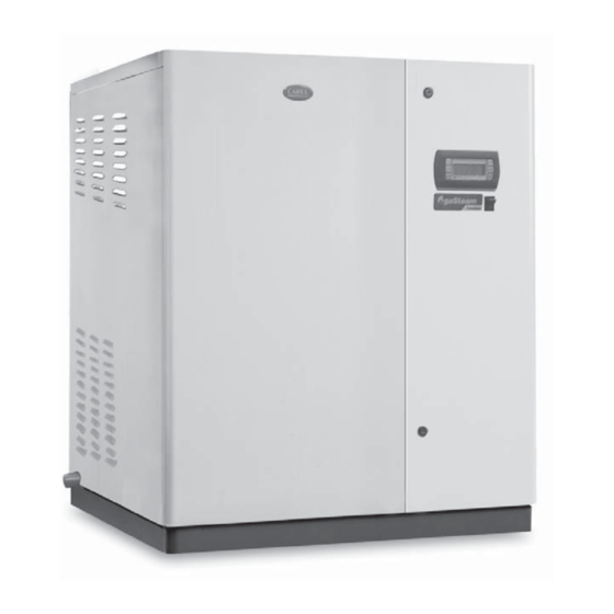
- Página 1 gaSteam 45/90/180 hardware Manual del usuario User manual...
- Página 3 Manual del usuario...
- Página 4 Garantía sobre los materiales: 2 años (desde la fecha de producción, excluidos los consumibles). Homologaciones: la calidad y la seguridad de los productos CAREL están garantizadas por el sistema de diseño y producción certifi cado por la ISO 9001, además de por las marcas TÜV y ETL.
-
Página 5: Tabla De Contenido
Indice 1. MODELOS Y DESCRIPCIÓN DE LOS COMPONENTES 1.1 Modelos ..............................7 1.2 Descripción de los componentes ......................7 2. MONTAJE 2.1 Recepción y conservación ........................8 2.2 Posicionamiento e impedimentos.....................8 2.3 Desmontaje y montaje de la cubierta frontal .................8 3. CONEXIONES HIDRÁULICAS 3.1 Características del agua de alimentación ..................9 3.2 Características del agua de drenaje ....................9 3.3 Conexión de las tuberías ........................9... -
Página 7: Modelos Y Descripción De Los Componentes
1. MODELOS Y DESCRIPCIÓN DE LOS COMPONENTES 1.1 Modelos El código que distingue el modelo de humidifi cador está compuesto por 10 caracteres (Fig. 1.a y Tab. 1.a). UG xxx x x 0 0 1 Ejemplo: el código UG180HD001 identifi ca un humidifi cador a gas (UG) con: 5 6 7 •... -
Página 8: Montaje
2. MONTAJE 2.1 Recepción y conservación • Controlar la integridad del humidifi cador a la recepción y notifi car inmediatamente al transportista, por escrito, cualquier daño que pueda ser atribuido a un transporte descuidado o inadecuado; • Transportar el humidifi cador al lugar de instalación antes de sacarlo del embalaje, agarrando el bulto sólo por debajo de la base;... -
Página 9: Conexiones Hidráulicas
6 mm. Éste se saca de un grifo de interceptación para permitir desconectar el aparato durante las operaciones de mantenimiento. Se aconseja utilizar el tubo fl exible CAREL (cod. FWH3415000) conectado a un grifo de interceptación para permitir desconectar el aparato durante las operaciones de mantenimiento. -
Página 10: Conexión Del Conducto De Aspiración De Aire Y De La Descarga De Humos
100 mm si la aspiración procede del lado posterior Fig. 3.c.b Accesorios de fumistería disponibles en CAREL: Ejemplo de la toma de aire del exterior. aparato de tipo C DESCRIPCIÓN Código terminal de aspiración Ø 80 mm EXHX080000 prolongación Ø... -
Página 11: Instalación Del Aparato Con Toma De Aire Del Ambiente (Tipo B)
La máxima pérdida de carga admitida en los conductos de aspiración de aire/descarga humos ø 80 mm es igual a: - para el gasteam 45: -50…90 Pa (-0,50…0,90 mbar / -0.007…0.013 PSI); - para el gasteam 90: -50…82 Pa (-0,50…0,82 mbar / -0.007…0.012 PSI);... -
Página 12: Distribución Del Vapor
Para la distribución del vapor en conductos de aire es indispensable el uso de un difusor de vapor proporcional a la potencia del humidifi cador y a la sección de la canalización. La Fig. 4.a muestra las DP085D40R0 dimensiones de los distribuidores lineales realizados en acero de CAREL. La Tab. 4.a indica el número 1015 DP105D40R0 (4)** mínimo y el modelo de los distribuidores aconsejados para el tipo de humidifi... -
Página 13: Instalación Del Tubo De Transporte Del Vapor
Advertencia IMPORTANTE: se recomienda que el tubo de transporte del vapor no genere una contra- presión superior a la mitad de la máxima soportable por el humidifi cador. Generalmente esto equivale a una longitud del tubo de unos 4 metros. Para aplicaciones particulares contactar con Carel. 4.4 Instalación del tubo de drenaje del condensado •... -
Página 14: Conexiones Eléctricas
5. CONEXIONES ELÉCTRICAS Antes de proceder a la realización de las conexiones, asegurarse de que la máquina esté desco- nectada de la red eléctrica. • Verifi car que la tensión de alimentación del aparato corresponda al valor indicado en los datos de la placa, en el interior del cuadro eléctrico. -
Página 15: Esquema De Las Conexiones Del Ug45-90
5.4 Esquema de las conexiones del UG45-90 LEVEL HIGH SENSOR MIDDLE PT1000-1 FLUE GASES BLOWER 1 TACH J11. TO CLIP J11.2 SHILDING 75 VA 230 V HONEYWELL 1 CONTROLLER BOARD 3 2 1 24 V KLIXON 1 J15. J14. COOLING FAN DRAIN PUMP 230 Vac CONTROL SENSOR... -
Página 16: Esquema De Las Conexiones Del Ug180
5.5 Esquema de las conexiones del UG180 BLOWER 2 TACH PT1000-2 FLUE GASES TO CLIP J11.2 SHILDING LEVEL HIGH SENSOR MIDDLE PT1000-1 BLOWER 1 FLUE GASES TACH J11. TO CLIP PRESS SHILDING J11.2 75 VA 230 V 3 2 1 HONEYWELL 1 CONTROLLER BOARD... -
Página 17: Adaptación Del Humidifi Cador A Los Distintos Tipos De Gas
5.6 Adaptación del humidifi cador a los distintos tipos de gas El humidifi cador puede ser alimentado con los siguientes tipos de gas: • G20-G25 (metano); • G30-G31 (propano-butano). Para poder permitir un funcionamiento correcto es indispensable regular algunos parámetros en el controlador electrónico (ver controlador pHC +030220531) como se indica en la tabla siguiente: UG45 UG90... -
Página 18: Mantenimiento Y Piezas De Recambio
6. MANTENIMIENTO Y PIEZAS DE RECAMBIO ANTES DE CUALQUIER OPERACIÓN: • desconectar el aparato de la red eléctrica; • cerrar los grifos del agua de red y del gas; • vaciar el circuito hidráulico del agua utilizando el mando de funcionamiento manual de la electrobom- ba o el grifo de drenaje. -
Página 19: Limpieza Del Quemador
6.2 Limpieza del quemador El control periódico del quemador debe ser efectuado por personal autorizado y cualifi cado una o dos veces al año, según el uso. Antes de proceder al control para el mantenimiento del quemador es aconsejable verifi car el estado general del mismo y realizar las operaciones indicadas a continuación: •... -
Página 20: Intercambiador
6.4 Intercambiador ver procedimiento en el párrafo 6.1 6.5 Sensor de temperatura humos El sensor de temperatura humos se encuentra insertado en el tubo de descarga de humos y no necesita de mantenimiento periódico. En el caso de que sea necesario sustituir el sensor, a causa de una avería del mismo, hay que seguir el siguiente procedimiento: •... -
Página 21: Principio De Funcionamiento Y Otras Funciones
7. PRINCIPIO DE FUNCIONAMIENTO Y OTRAS FUNCIONES 7.1 Principio de funcionamiento En un humidifi cador a gas la producción de vapor se obtiene en el interior de un calderín que contiene agua que se calienta hasta alcanzar y mantener la ebullición. El calor necesario para la ebullición es su- ministrado por un intercambiador de calor, calentado por un quemador de gas premezclado modulante de tipo C (en lo que respecta a la Normativa), es decir, estanco, que aspira el aire para la combustión y descarga de los humos al exterior. -
Página 22: Características Técnicas
8. CARACTERÍSTICAS TÉCNICAS modelos UG045 UG090 UG180 tensión nominal de alimentación (Vca) conexión de vapor (Ø mm) 2x40 2x40 4x40 límites de la presión de impulsión de vapor (Pa) 0…2000 (0…0.30 PSI) condiciones de funcionamiento 1T40 °C (33T104 °F); 10...90% HR sin cond. condiciones de almacenaje -10T70 °C (14T158 °F), 5…95% HR grado de protección... -
Página 23: Dimensiones
8.3 Dimensiones Dimensiones en mm (pulgadas): UG045-090 Fig. 8.a Dimensiones en mm (pulgadas): UG180 Fig. 8.b DESCRIPCIÓN UG045-090 UG180 UG045-090 UG180 UG045-090 UG180 UG045-090 UG180 salida de vapor 40 (1.574) 1020 (40.157) 1200 (47.244) 570 (22.441) 930 (36.614) descarga de humos 80 (3.150) 204 (8.031) 168 (6.614) -
Página 24: Pesos
2H G20 20mbar 2E G20 20mbar 2ELL G20-G25 20mbar 2Esi G20/G25 20/25mbar 2L G25 25mbar Fig. 8.e - UG180 CAREL se reserva el derecho a realizar cambios a sus productos sin previo aviso. gaSteam HARDWARE +030220538 - rel. 1.4 - 22.01.2008... - Página 25 User manual...
- Página 26 Warranty on materials: 2 years (from the date of production, excluding the consumable parts, such as the cylinder). Certifi cation: the quality and safety of CAREL products are guaranteed by CAREL’s ISO 9001 certifi ed design and production system, as well as the TÜV, CE and ETL marks.
- Página 27 Content 1. MODELS AND DESCRIPTION OF THE COMPONENTS 1.1 Models ..............................7 1.2 Description of the components ......................7 2. ASSEMBLY 2.1 Receipt and storage..........................8 2.2 Positioning and dimensions .......................8 2.3 Removal and reassembly of the front cover ...................8 3. WATER CONNECTIONS 3.1 Characteristics of the supply water ....................9 3.2 Characteristics of the drain water ......................9 3.3 Pipe connections ...........................9...
-
Página 29: Models And Description Of The Components
1. MODELS AND DESCRIPTION OF THE COMPONENTS 1.1 Models The code that marks the model of humidifi er is made up of 10 characters (Fig. 1.a and Table 1.a). UG xxx x x 0 0 1 Example: the code UG180HD001 identifi es a gas-fi red humidifi er (UG) with: 5 6 7 •... -
Página 30: Assembly
2. ASSEMBLY 2.1 Receipt and storage • Check that the humidifi er is intact upon delivery and immediately notify the carrier, in writing, of any damage that may be due to careless or improper transport; • Move the humidifi er to the site of installation before removing it from the packaging, holding the neck only from below the base;... -
Página 31: Water Connections
The connection to the gas supply is made using a metal hose (with vibration-damping joint) supplied, connected to a tap (manual shut-off valve), with a 1”G fi tting for the gaSteam 45 and 90, and a 1” 1/4G fi tting for the gaSteam 180. -
Página 32: Air Inlet And Fl Ue Connections
UNI-CIG 7129, UNI-CIG 7131 standards and their subsequent amendments), and therefore the validity of the diagrams below should always be checked. The maximum lengths indicated in the following installations have been calculated using CAREL/Ecofl am ducting. Four openings are available for the air intake and fl ue gas outlet (eight on the UG180): •... -
Página 33: Pressure Switch
The maximum pressure drop allowed along the 80 mm diam. air intake pipes/fl ues is: - for the gaSteam 45: -50…90 Pa (-0,50…0,90 mbar / -0.007…0.013 PSI); - for the gaSteam 90: -50…82 Pa (-0,50…0,82 mbar / -0.007…0.012 PSI);... -
Página 34: Steam Distribution
4.1 Steam distribution in ducts - linear distributors For steam distribution into air ducts, the steam distributor must be sized according to the output of the DP085D40R0 humidifi er and the cross-section of the ducting. Figure 4.a provides the dimensions of the CAREL linear 1015 DP105D40R0 (4)** steel distributors. -
Página 35: Installation Of The Steam Hose
• the paths of the steam and condensate hoses comply with the instructions provided in this chapter; • the length of the steam hose should not exceed 4 m; for special applications, contact CAREL; • the slope of the steam hose is suffi cient to allow correct dragging of the condensate (> 20° for the upward sections, >... -
Página 36: Electrical Connections
5. ELECTRICAL CONNECTIONS Before making the connections, ensure that the unit is disconnected from the mains power supply. • Check that the power supply voltage of the appliance corresponds to the value indicated on the rating plate inside the electrical panel, •... -
Página 37: Connection Diagram, Ug45-90
5.4 Connection diagram, UG45-90 LEVEL HIGH SENSOR MIDDLE PT1000-1 FLUE GASES BLOWER 1 TACH J11. TO CLIP J11.2 SHILDING 75 VA 230 V HONEYWELL 1 CONTROLLER BOARD 3 2 1 24 V KLIXON 1 J15. J14. COOLING FAN DRAIN PUMP 230 Vac CONTROL SENSOR + 15 V... -
Página 38: Connection Diagram, Ug180
5.5 Connection diagram, UG180 BLOWER 2 TACH PT1000-2 FLUE GASES TO CLIP J11.2 SHILDING LEVEL HIGH SENSOR MIDDLE PT1000-1 BLOWER 1 FLUE GASES TACH J11. TO CLIP PRESS SHILDING J11.2 75 VA 230 V 3 2 1 HONEYWELL 1 CONTROLLER BOARD 24 V KLIXON 1... -
Página 39: Adjusting The Humidifi Er To Different Types Of Gas
5.6 Adjusting the humidifi er to different types of gas The humidifi er can be supplied with the following types of gas: • G20-G25 (natural gas); • G30-G31 (propane-butane). A number of parameters on the electronic controller need to be set for correct operation (see the pHC controller manual, code +030220531) as shown in the table below: UG45 UG90... -
Página 40: Maintenance And Spare Parts
6. MAINTENANCE AND SPARE PARTS BEFORE ALL OPERATIONS: • disconnect the appliance from the mains power supply; • close the mains water and gas taps; • drain the water circuit using the manual electric pump function, or drain. IMPORTANT WARNINGS: •... -
Página 41: Cleaning The Burner
6.2 Cleaning the burner The burner must be checked by authorised and qualifi ed personnel once or twice a year, according to use. Before performing any maintenance on the burner, check its general condition, carrying out the opera- tions listed below: •... -
Página 42: Heat Exchanger
6.4 Heat exchanger See the procedure in paragraph 6.1 6.5 Flue gas temperature sensor The fl ue gas temperature sensor is located in the fl ue and does not require periodical maintenance. If the sensor needs to be replaced due to a fault, proceed as follows: •... -
Página 43: Operating Principle And Other Functions
7. OPERATING PRINCIPLE AND OTHER FUNCTIONS 7.1 Operating principle In a gas humidifi er the production of steam is obtained inside a boiler containing water that is heated to and then held at boiling temperature. The heat required to boil the water is provided by a heat exchan- ger, heated by a type C pre-mix modulating room-sealed gas burner (standards compliant), which takes in air for combustion and discharges the fl... -
Página 44: Technical Specifications
8. TECHNICAL SPECIFICATIONS model UG045 UG090 UG180 rated power supply voltage (Vac) steam connection (dia. mm) 2x40 2x40 4 x40 steam outlet pressure limits (Pa) 0 to 2000 (0…0,30 PSI) operating conditions 1T40 °C (33T104 °F); 10..90% rH non condensing storage conditions -10T70 °C (14T158 °F), 5…95% rH index of protection... -
Página 45: Dimensions
8.3 Dimensions Diemnsions in mm (inch): UG045-090 Fig. 8.a Diemnsions in mm (inch): UG180 Fig. 8.b description UG045-090 UG180 UG045-090 UG180 UG045-090 UG180 UG045-090 UG180 steam outlet 40 (1.574) 1020 (40.157) 1200 (47.244) 570 (22.441) 930 (36.614) fl ue 80 (3.150) 204 (8.031) 168 (6.614) 658 (25.905) 629 (24.764) -
Página 46: Weights
2H G20 20mbar 2E G20 20mbar 2ELL G20-G25 20mbar 2Esi G20/G25 20/25mbar 2L G25 25mbar Fig. 8.e - UG180 CAREL reserves the right to modify the features of its products without prior notice. gaSteam HARDWARE +030220538 - rel. 1.4 - 22.01.2008... - Página 48 Agenzia / Agency: CAREL S.p.A. Via dell’Industria, 11 - 35020 Brugine - Padova (Italy) Tel. (+39) 049.9716611 - Fax (+39) 049.9716600 e-mail: carel@carel.com - www.carel.com...