Carel ultimateSAM Manual Del Usuario
Ocultar thumbs
Ver también para ultimateSAM:
- Manual del usuario (56 páginas) ,
- Manual del usuario (30 páginas)
Tabla de contenido
Publicidad
Idiomas disponibles
Idiomas disponibles
Enlaces rápidos
Publicidad
Capítulos
Tabla de contenido

Manuales relacionados para Carel ultimateSAM


Resumen de contenidos para Carel ultimateSAM
- Página 1 Sistema de humectación ultimateSAM Direct Steam Humidifi cation System Manual del usuario User manual NO POWER & SIGNAL CABLES TOGETHER READ CAREFULLY IN THE TEXT! I n t e g r a t e d C o n t r o l S o l u t i o n s & E n e r g y S a v i n g s...
- Página 3 fi nal específi co. CAREL INDUSTRIES, en ese caso, previo acuerdo específi co, puede intervenir como consultor para llevar a buen puerto la puesta en marcha de la máquina/aplicación fi...
-
Página 5: Tabla De Contenido
La humedad supera el punto de consigna ..........21 La humedad no alcanza el punto de consigna ........21 Formación de condensado en el conducto ..........22 Pérdida de vapor por/a través del sifón .............22 “ultimateSAM - user” +0300070ES - rel. 1.0 - 23.05.2013... -
Página 7: Introducción Y Ensamblaje
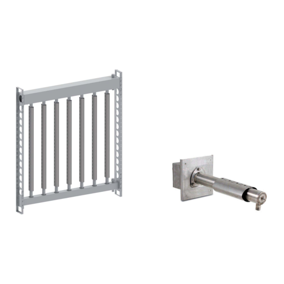
1. INTRODUCCIÓN Y ENSAMBLAJE 1.1 El sistema de humectación ultimateSAM SA x (SA*) Cada sistema de humectación ultimateSAM está constituido por los siguientes componentes: Prefi jo • Un distribuidor de vapor Tipo B= Alimentación inferior • Componentes para el vapor a presión, como: actuadores, válvulas, alimentación... -
Página 8: Dimensiones Y Pesos Del Distribuidor Sa0 (Single-Pipe)
“Especifi caciones técnicas. ” Ver las otras secciones de este manual • Apretar los tornillos con un par de 7-8 Nm (5-6 ft lb), asegurándose de para los detalles sobre los otros componentes del sistema ultimateSAM. que los componentes estén montados a escuadra; 1.3 Apertura del embalaje 82.5 mm... -
Página 9: Ensamblaje Del Bastidor, Version Sa0 (Single-Pipe)
1.4.2 Ensamblaje del bastidor, version SA0 (single- Fig. 1.j Fig. 1.k pipe) Los distribuidores ultimateSAM en la versión SA0******* se suministran con un bastidor para ensamblar, que consta de los siguientes componentes: • Colector que incluye brida de apoyo; •... -
Página 10: Posicionamiento
Posicionamiento Posibles posicionamientos del distribuidor: • Determinar la posición óptima del distribuidor ultimateSAM en el Óptima: Sufi cientemente lejos del ventilador para evitar turbulencias. conducto. (Fig.1.j). La mayor parte de los problemas de absorción de Mantener una longitud libre adecuada para la absorción.. -
Página 11: Montaje De Los Modelos Sab/Sat
Cubrir Fig. 1.q Nota: el adaptador de entrada, la válvula de regulación, el actuador, el descargador de condensado y el fi ltro mostrados anteriormente están disponibles opcionalmente. Los sifones de desagüe “ultimateSAM - user” +0300070ES - rel. 1.0 - 23.05.2013... -
Página 12: Instalación Interna En La Central De Tratamiento De Aire
Caudal efectivo de lanza única ≤ 50kg/h (110lb/h) -> H=150mm (5.9in) Altura mínima AHU: 300mm (11.8in) Caudal efectivo de lanza única > 50kg/h (110lb/h) -> H=200mm (7.9in) Altura mínima AHU: 400mm (15.8in) “ultimateSAM - user” +0300070ES - rel. 1.0 - 23.05.2013... -
Página 13: Caudal De Vapor De Las Lanzas
Las lanzas que componen el ultimateSAM son de dos diámetros distintos. Caudal efectivo de lanza única ≤ 50kg/h (110lb/h) En la confi guración de tipo “S” (6° dígito del código ultimateSAM) las H=150mm (5.9in) L=420mm (16.5in) lanzas tienen diámetro de 35mm (1.37”), para aumentar el caudal de la Altura mínima AHU: 720mm (28.3in) -
Página 14: Conexiones De Entrada De Vapor
2.1.2 Adaptadores de entrada de vapor para SA0 (single-pipe) El ultimateSAM SA0 está dotado de entrada de vapor con diámetro 1 “ de Fig. 2.a tipo GAS ó 1 ½ ” tipo NPT (mercado Americano). Por lo tanto, en el caso de alimentación con vapor a presión no es necesario el uso de adaptadores, será... -
Página 15: Instalación De Los Adaptadores De Entrada
SAKI****** Para el ultimateSAM están previstos kits de conexión entre la entrada del vapor del distribuidor y la brida de la válvula. Estos kits varían según la conexión de la entrada de vapor del distribuidor y del DN de las válvulas. -
Página 16: Conexiones De Vaciado De Condensado
Es necesario instalar un sifón en la línea de vaciado conectada a la conexión de ¾” posicionada sobre el fondo de cada colector. Esta tiene Para las aplicaciones en las cuales el ultimateSAM es alimentado con una rosca macho ¾” NPT para el mercado norteamericano y ¾” Gas para vapor presurizado, es necesario instalar un fi... -
Página 17: Drenaje En La Línea De Entrada Para Distribuidores Alimentados Con Vapor A Presión Atmosférica
SAKT presión atmosférica En el caso de que el ultimateSAM esté conectado directamente a un humidifi cador (Fig.3.dc), el descargador de condensado puede no ser necesario, si la instalación permite al condensado que se forma en el Prefi... -
Página 18: Modo De Vaciado De Condensado Para Sa0 (Single-Pipe) (Opcionales Vendidos Por Separado)
O.D. mm (in) 10= 10 mm (0.40) suministrada en dotación con el descargador termostático. O.D. Mercado Other / Otros (GAS) Norteamérica (NPT) Libre Tab. 3.d Fig. 3.l Fig. 3.h “ultimateSAM - user” +0300070ES - rel. 1.0 - 23.05.2013... -
Página 19: Conexiones De Alimentación De Vapor
En caso de que los kits de actuador y válvula no fueran sobre las tuberías de conexión al distribuidor ultimateSAM. En el caso de pedidos con el distribuidor ultimateSAM, consultar la guía técnica válvulas de regulación con conexiones roscadas (NPT), pueden ser... -
Página 20: Conexión De La Línea De Vapor A Presión A Un Distribuidor Ultimatesam
Instalar la prologación sobre el colector, si es necesario. Notas: los sifones mostrados arriba no forman parte del sistema ultimateSAM.. Fig. 4.o “ultimateSAM - user” +0300070ES - rel. 1.0 - 23.05.2013... -
Página 21: Funcionamiento
5. FUNCIONAMIENTO El sistema de humectación ultimateSAM distribuye vapor en un conducto En el caso de alimentación con vapor a presión atmosférica (humidifi cador), para el tratamiento del aire. El control del caudal de vapor introducido El caudal se determina por la carga requerida al humidifi cador mismo. -
Página 22: Formación De Condensado En El Conducto
8.2 Kit de colector horiz ontal (entrada de vapor - desagüe de condensado) para Kit de pedestal para aumentar la distancia de la base del ultimateSAM del SAB* / SAT* conducto. En la fi g.8.a el pedestal cód. SAKS010000 se muestra en dos... -
Página 23: Kit De Distribuidores Verticales Para Sab* / Sat
SAB* / SAT* Kit de bastidor utilizable tanto como hombro (lado derecho o lado izquierdo) o come bastidor transversal en el caso del ultimateSAM con entrada de vapor del colector inferior (SAB*). Ejemplo: el kit SAKFF0G000 es un hombro de 1.305 mm con 17 taladros, puede ser utilizado como: •... -
Página 24: Kit De Juntas
Tab. 8.i Brida DN 40 Tubo roscado 1” Brida DN 50 Brida DN 65 Tubo roscado 2” Mercado: 0 = Otros U = U.S. Tab. 8.g Fig. 8.k Fig. 8.i “ultimateSAM - user” +0300070ES - rel. 1.0 - 23.05.2013... -
Página 25: Kit De Descargador De Condensado De Cubo Inverso
• Informaciones obtenidas de Sauter S.p.a Cada kit SAKU0*LI*0 incluye: • el tubo de distribución • 1 junta tórica • bulones para la fi jación del distribuidor al colector Fig. 8.m “ultimateSAM - user” +0300070ES - rel. 1.0 - 23.05.2013... - Página 26 Procedimiento de instalación de SA0 - colector externo UTA - con kit de revestimiento de pared UTA Descripción del procedimiento de instalación del ultimateSAM en versión SA0* (single-pipe), con colector externo a la unidad de tratamiento de aire e instalación del kit de revestimiento de la pared interna de la UTA.
- Página 27 SAKIL00000 Instalación del Kit de desagüe de condensado para SA0 (single-pipe) Instalación del Kit de descargador termostático para SA0 (opcional, vendido por separado) SACK*S10*0 (single-pipe) (opcional, vendido por separado) SAKT*H00*0 “ultimateSAM - user” +0300070ES - rel. 1.0 - 23.05.2013...
- Página 28 Notes “ultimateSAM - user” +0300070ES - rel. 1.0 - 23.05.2013...
- Página 29 The technical specifi cations shown in the manual may be changed without prior warning. The liability of CAREL Industries in relation to its products is specifi ed in the CAREL Industries general contract conditions, available on the website www.carel.
- Página 31 Steam valve will not open ..................21 Steam valve will not close...................21 Steam valve is leaking ...................21 Humidity exceeds set point ................21 Humidity remains below set point ...............21 Condensate in duct ....................22 Steam leaks from P-traps..................22 “ultimateSAM - user” +0300070ES - rel. 1.0 - 23.05.2013...
-
Página 33: Introduction And Assembly
24.5 ( 54) locations, see the “Technical specifi cations” manual. See other sections of SATA*H3*0 10.5 ( 23) 28.0 ( 62) this manual for details on other ultimateSAM items, such as valves and SATR*SI3*0 55.0 (121) 137.0 (301) traps. SATR*LI3*0 56.5 (124) -
Página 34: Dimensions And Weights Of The Sa0 (Single-Pipe) Distributor
Tab. 1.d For other distances and measurements relating to the distributor see the “Technical specifi cations” manual. See the remaining sections of this manual for details on the other components of the ultimateSAM system. 82.5 mm (3.25 in) 37.5 mm (1.48 in) -
Página 35: Assembling The Frame, Sa0 (Single-Pipe) Versions
O-ring Fig. 1.f 1.4.2 Assembling the frame, SA0 (single-pipe) versions Fig. 1.j Fig. 1.k The ultimateSAM version SA0******* distributors are supplied with a frame to be assembled, which comprises the following components: • manifold with support fl ange • upright •... -
Página 36: Positioning
Positioning BEST: locate distributor far enough from fan to avoid turbulence. Maintain • Determine the proper position for the ultimateSAM distributor in the adequate evaporation distance. duct or AHU. (Fig.1.j) Most steam absorption problems are the result of GOOD: provided there is enough distance from the distributor to the fan improper positioning. -
Página 37: Mounting Sab/Sat Models
Nota: The inlet adapter, control valve, actuator, trap, and strainer elements supplied; shown above are available as options. The “P” drains are not If necessary, secure the end of the upright. provided as part of the ultimateSAM system. “ultimateSAM - user” +0300070ES - rel. 1.0 - 23.05.2013... -
Página 38: Sa0 (Single-Pipe) Minimal Clearances
Eff ective single upright fl ow-rate ≤ 50kg/h (110lb/h) H=150mm (5.9in) L=250mm (9.8in) Minimum AHU height: 400mm (15.8in) Eff ective single upright fl ow-rate > 50kg/h (110lb/h) H=150mm (5.9in) L=250mm (9.8in) Minimum AHU height: 450mm (17.7in) “ultimateSAM - user” +0300070ES - rel. 1.0 - 23.05.2013... -
Página 39: Upright Steam Fl Ow-Rate
“S” confi guration (6th digit of the ultimateSAM code) the diameter of the uprights is 35 mm ( 1.37”), to increase fl ow-rate on single uprights there is also the “L” confi guration (6th digit of the ultimateSAM code) in which the diameter of the uprights is 45 mm ( 1.77”). -
Página 40: Steam Inlet Connections
2.1.2 Steam inlet adapters for SA0 (single-pipe) The ultimateSAM SA0 has a steam inlet with 11/2 “GAS or 1 ½ ” NPT (American market) fi tting. When supplied with pressurised steam no adapters need to be used, simply connect the steam inlet on the manifold to a 11/2 “ GAS (1 ½... -
Página 41: Installing Inlet Adapters
2.3 Steam inlet connection between ultimateSAM and valve fl ange (SAKI******) Connection kits are available for ultimateSAM between the distributor steam inlet and the valve fl ange. These kits vary depending on the distributor steam inlet connection and valve nominal diameter. -
Página 42: Drain Connections
North American markets and ¾” Gas for the other regions (for the SA0 For installations in which the ultimateSAM distributor is supplied with single-pipe: ½“ GAS or ½“ NPT). Given the minimal pressure inside the pressurized steam, a trap and strainer are required at the inlet of the header, a P-trap is generally suitable for the header drains. -
Página 43: Inlet Drains For Distributors Connected To Atmospheric Steam Supplies
SAKT When used with an atmospheric humidifi er, as shown in (Fig.3.e and Fig. 3.f ), an inlet trap may not be needed on the ultimateSAM distributor. In a typical installation, the condensate in the connecting hose drains back to the humidifi er. In special situations when the condensate cannot drain ... -
Página 44: Modalità Di Scarico Condensa Per Sa0 (Single-Pipe) (Opzionali Venduti Separatamente)
10= 10 mm (0.40) solution, the quick coupling supplied with the thermostatic steam trap Region Other (GAS) is not needed. North America (NPT) Free Tab. 4.d Fig. 4.x Fig. 4.t “ultimateSAM - user” +0300070ES - rel. 1.0 - 23.05.2013... -
Página 45: Steam Supply Connections
A control valve is needed to regulate the fl ow of pressurized steam Nota: For fl anged control valves, the installer must provide the to an ultimateSAM distributor. Actuators for the control valve are appropriate fi ttings and piping to connect the valve to the sold separately. -
Página 46: Connecting Pressurized Steam To An Ultimatesam Distributor
Attach the optional actuator, SAKA******, to the control valve. Nota: The adapters and steam hoses shown above are available as • options. The “P” drains are not provided as part of the ultimateSAM • Connect the valve/actuator assembly to the inlet adapter on the system. -
Página 47: Operation
All of the steam generated by the controlled depends upon whether the steam comes from a pressurized humidifi er is discharged by the ultimateSAM distributor into the duct or source or an atmospheric source. For pressurized steam supplies, the AHU. -
Página 48: Condensate In Duct
If there is with each of these devices. These accessories should be inspected at evidence of a steam leak at one of the static seals, contact CAREL. least once a year. For systems in which the inlet pressure to the control valve is greater than 0.7 bar (10 psig), more frequent inspections of the... -
Página 49: Uprights Kit For Sab* / Sat
SAT* Frame kit used either as a shoulder (right- or left-hand side) or as a cross- piece for ultimateSAM with bottom steam feed (SAB*). Example: kit SAKFF0G000 is a 1305 mm shoulder with 17 holes, and can be used as: •... -
Página 50: Retainer Ring Kit For Sab
U = U.S. Threaded pipe 1” Tab. 9.i Flange DN 50 Flange DN 65 Threaded pipe 2” Region: 0 = Other U = U.S. Tab. 9.g Fig. 9.k Fig. 9.i “ultimateSAM - user” +0300070ES - rel. 1.0 - 23.05.2013... -
Página 51: Inverted Bucket Condensate Drain Kit
The actuator can be installed in any position between vertical (best) and Each SAKU0*LI*0 kit horizontal. includes: • Information provided by Sauter S.p.a • upright; • 1 O-ring; • bolts for fastening the upright to the manifold. Fig. 9.m “ultimateSAM - user” +0300070ES - rel. 1.0 - 23.05.2013... - Página 52 SA0 installation procedure - manifold outside of AHU - with AHU wall cover kit Description of the installation procedure for ultimateSAM version SA0* (single-pipe), with manifold outside of the air handling unit and installation of the wall cover kit inside the AHU.
- Página 53 Apply the AHU wall cover kit for SA0 (not supplied, available separately): SAKIL00000 Installation of the condensate drain kit for SA0 (single-pipe) Installation of the thermostatic drain kit for SA0 (single-pipe) (optional, sold separately) SACK*S10*0 (optional, sold separately) SAKT*H00*0 “ultimateSAM - user” +0300070ES - rel. 1.0 - 23.05.2013...
- Página 54 Note “ultimateSAM - user” +0300070ES - rel. 1.0 - 23.05.2013...
- Página 56 Agenzia / Agency: CAREL INDUSTRIES HQs Via dell’Industria, 11 - 35020 Brugine - Padova (Italy) Tel. (+39) 0499 716611 - Fax (+39) 0499 716600 carel@carel.com - www.carel.com...