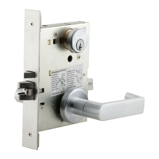
Schlage HSLR L9000 Serie Instrucciones De Instalación
Ocultar thumbs
Ver también para HSLR L9000 Serie:
- Instrucciones de instalación (24 páginas) ,
- Manual del usuario (20 páginas) ,
- Instrucciones de instalación (8 páginas)
Publicidad
Idiomas disponibles
Idiomas disponibles
*P519-054*
P519-054
EU/EL Spindle for
L9093, L9095, L9493
Functions
L9000-Series HSLR
WARNING
This installation requires two people. DO NOT attempt to
install alone. Pesonal injury and lock damage may occur.
Para español, pág. 5.
Para francés, pág. 9.
Customer Service
1-877-671-7011
www.allegion.com/us
Installation Instructions
Tools
•
Two (2) drivers to fit
T15 security Torx bits
(bits included)
•
Phillips screw driver
Publicidad
Tabla de contenido

Resumen de contenidos para Schlage HSLR L9000 Serie
- Página 1 *P519-054* L9000-Series HSLR P519-054 Installation Instructions EU/EL Spindle for L9093, L9095, L9493 Functions Tools • Two (2) drivers to fit T15 security Torx bits (bits included) • Phillips screw driver WARNING This installation requires two people. DO NOT attempt to install alone.
- Página 2 Prepare door using included template. Assemble posts onto interior plate. pl at ió n n Te al ac in st la tio al la st al In st d’ in til la ar it G ab n s: ct io ci ó...
- Página 3 5c Insert posts into holes. 6c CYLINDER FUNCTIONS: install cylinder(s) now. See "Cylinder functions" on page 4. Lock case should Ì Ì 6d Install remaining screws, but do not fully tighten. remain unlocked. Plates will vary based on lock function. Actual Size (3) Plates will vary based on lock function.
- Página 4 Install strike. Troubleshooting Lever binding when rotating. 1. Loosen the five (5) perimeter screws on one side of the trim. (Do not loosen the one nearest the latch.) 2. Push both lever trim assemblies slightly upwards and hold in place (not too far, but enough to get rid of the bind). Actual Size (2) 3.
-
Página 5: Servicio Al Cliente
L9000-Series HSLR Instrucciones para la instalación Vástago EU/EL por L9093, L9095, L9493 Funciones Herramientas • Dos (2) desarmadores de puntas intercambiables para las puntas Torx de seguridad T15 ADVERTENCIA (puntas incluidas) Se necesitan dos personas para esta instalación. NO intente realizar •... - Página 6 Prepare la puerta con ayuda de la plantilla adjunta. Ensamble los puntales sobre la placa interior. pl at ió n n Te al ac in st la tio al la st al In st d’ in til la ar it G ab n s: ct io...
- Página 7 5b Ajuste la manija y el dispositivo de llave mariposa (si los tiene) Instale la placa exterior sobre el exterior de la puerta. para la instalación. 6a Install spindle and then spring cage. FUNCIONES CON CERROJO FUNCIONES SIN CERROJO: y L9040, L9044, L9056: Gire el dispositivo de llave Las flechas en la caja Las placas variarán según...
-
Página 8: Funciones Del Cilindro
Ajuste completamente todos los tornillos de la placa y Funciones del cilindro del chasis. a. Instale el cilindro y el resorte en el anillo de bloqueo. Si no funciona con un movimiento suave y fluido, consulte "Resolución de problemas" en la página 8. ADVERTENCIA b. -
Página 9: Service À La Clientèle
*P519-054* L9000-Series HSLR P519-054 Instructions d’installation Axe EU/EL pour L9093, L9095, L9493 Fonctions Liste des outils • Deux (2) pilotes pour adapter les douilles à six lobes pour entrainement de sécurité T15 (douilles fournies) AVERTISSEMENT • Tournevis à tête Cette installation doit être effectuée par deux (2) personnes. cruciforme N’ESSAYEZ PAS d’effectuer l’installation à... - Página 10 Préparez la porte en utilisant le gabarit fourni. Assemblez les supports sur la plaque intérieure. pl at ió n n Te al ac in st la tio al la st al In st d’ in til la ar it G ab n s: ct io ci ó...
- Página 11 5c Insérez les supports dans les trous. 6c FONCTIONS DU CYLINDRE :installez maintenant les cylindres. Consultez « Funciones del cilindro » à la page 8. Le coffre de la serrure Ì Ì 6d Installez les vis restantes, mais sans les serrer complètement. doit rester déverrouillé.
- Página 12 Installez la gâche. Dépannage Grippage du levier lors de la rotation. 1. Desserrez les cinq (5) vis périmétriques sur un côté de la garniture. (Ne desserrez pas celle qui se trouve le plus près du taquet.) 2. Poussez légèrement les deux ensembles de garniture de levier Dimension réelle (2) vers le haut et maintenez-les en place (pas trop loin, mais suffisamment pour vous débarrasser du grippage).


