Tabla de contenido
Publicidad
Idiomas disponibles
Idiomas disponibles
Enlaces rápidos
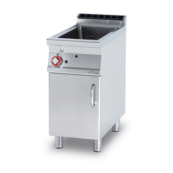
BRASIERA A GAS
PER USO PROFESSIONALE
GASBETRIEBENE
BRATPFANNEN
FÜR GROSSKÜCHEN
BRAISIERES A GAZ USAGE
PROFESSIONEEL
GAS BRATPAN FOR
PROFESSIONAL USE
CACEROLAS A GAS
PARA USO PROFESIONAL
IT
DE
FR
GB
Mod.
BRF-94G
Categorie Kategorien Catégories Categories Categorías
II2H3B/P
II2E+3+
II2ELL3B/P
II2H3B/P
I2E
I3B/P
CH
per l'installazione e l'uso
AT
CH
und Bedienungsanleitung
BE
Pour l'installation et l'emploi
IE
for installation and use
Guia para la intalación e
ES
BRF-98G
II2H3+
II2H3B/P
II2L3B/P
II2E3P
I3+
II2E3B/P
Istruzioni
Aufstellungs
Instructions
Instructions
instrucciones de uso
563008501.doc
LIBR.ISTR.BRF90G
Publicidad
Capítulos
Tabla de contenido

Manuales relacionados para Lotus BRF-94G


Resumen de contenidos para Lotus BRF-94G
- Página 1 PROFESSIONEEL Instructions GAS BRATPAN FOR for installation and use PROFESSIONAL USE CACEROLAS A GAS Guia para la intalación e PARA USO PROFESIONAL instrucciones de uso Mod. BRF-94G BRF-98G 563008501.doc LIBR.ISTR.BRF90G Categorie Kategorien Catégories Categories Categorías II2H3B/P II2E+3+ II2H3+ II2H3B/P II2ELL3B/P...
- Página 2 FIG. A 562006601 M00_00 Targhetta caratteristiche Attacco gas ISO 7-1 R1/2M Typenschild Gasanschluss ISO 7-1 R1/2M Plaque des caractéristiques Raccord gaz ISO 7-1 R1/2M Data plate Gas connection ISO 7-1 R1/2M Chapa de características Conexión gas ISO 7-1 R1/2M...
- Página 3 FIG. B FIG. C By-pass...
- Página 4 FIG. D Piezoelettrico Piezoelektrischer Anschluss Piézoélectrique Piezoelectric device Piezo eléctrico FIG. E FIG. F Staffa Bügel Bride Brida Iniettore Pilota Zündflamme Veilleuse Piloto Einspritzventil Termocoppia Thermoelement Thermocouple Termopar Injecteur Candela accensione Zündkerze Bougie d'allumage Candela encendido Injector...
- Página 5 FIG. G...
- Página 6 ESEMPIO DI FISSAGGIO PER APPARECCHI BEISPIEL DER FESTSETZUNG FUER GERAETE EXEMPLE DE MONTAGE POUR EQUIPEMENTS EXAMPLE OF FIXING FOR EQUIPMENT EJEMPLO FIJACIÓN DE APARATO 562026000 M00_00...
- Página 7 Pag. Seite Page Page Pàg.
-
Página 8: Tabla De Contenido
INDICE DICHIARAZIONE DI CONFORMITA’ ........................9 TABELLA DATI TECNICI ............................9 INSTALLAZIONE DELL'APPARECCHIO......................... 9 VERIFICA DELLA CORRETTA VENTILAZIONE ....................9 Per l'Italia: ................................9 Per la Svizzera: ................................ 9 TUBO PER IL COLLEGAMENTO DEL GAS ......................10 CONTROLLO DELLA POTENZA TERMICA ......................10 Allacciamento per il gas liquido G30/G31 ...................... -
Página 9: Dichiarazione Di Conformita
DICHIARAZIONE DI CONFORMITA’ Il costruttore dichiara che gli apparecchi sono conformi alle prescrizioni della direttiva CEE 90/396. L’installazione dovrà essere effettuata in osservanza delle norme vigenti soprattutto in merito all’aerazione dei locali e al sistema di evacuazione dei gas di scarico. N.B.: Il costruttore declina ogni responsabilità... -
Página 10: Tubo Per Il Collegamento Del Gas
TUBO PER IL COLLEGAMENTO DEL GAS L’allacciamento del gas é da effettuarsi con tubazioni in acciaio oppure in rame o diversamente, con tubazioni flessibili in acciaio, in conformità alla norma nazionale se esistente. Ogni apparecchio deve essere dotato di un rubinetto d’intercettazione del gas e di chiusura rapida. -
Página 11: Disposizioni Per La Trasformazione Ed Installazione Per Altri Tipi Di Gas
DISPOSIZIONI PER LA TRASFORMAZIONE ED INSTALLAZIONE PER ALTRI TIPI DI GAS I nostri apparecchi vengono collaudati e regolati a gas liquido (vedere targhetta). La trasformazione o l’adattamento ad un altro tipo di gas deve essere eseguita da un tecnico specializzato. Gli ugelli per i vari tipi di gas sono contenuti in un sacchetto compreso nella fornitura e sono contrassegnati in centesimi di mm (Vedi tabella “Dati tecnici bruciatori”). -
Página 12: Accensione Dell'apparecchio
Le brasiere fisse sono apparecchi che consentono la cottura di carne, pesce, uova, verdure, formaggio, spezzatino, risotti ecc.. ACCENSIONE DELL’APPARECCHIO Accensione bruciatore pilota Premere e ruotare la manopola del termostato (01) in posizione Tenere la manopola premuta, quindi azionare ripetutamente il pulsante piezoelettrico (03). La fiamma si accende automaticamente ed è... -
Página 13: Apparecchi Di Tipo "B11" (Vedi Targhetta Caratteristiche)
1)Cappa aspirante 1) Cappa aspirante 2) Asservimento Apparecchi di tipo "B11" (Vedi targhetta caratteristiche) 1) Evacuazione naturale (fig.3) Collegamento ad un camino a tiraggio naturale, di sicura efficienza a mezzo del raccordo antivento, con scarico dei prodotti della combustione direttamente all'esterno. 2) Evacuazione forzata (fig.4) L'alimentazione del gas all'apparecchio deve essere direttamente asservita al sistema di evacuazione forzata, e deve interrompersi nel caso che la portata di questo scenda sotto i valori prescritti dal punto 4.3 della norma UNI-CIG 8723. - Página 14 INHALTSANGABE KONFORMITÄTSERKLÄRUNG ..........................15 INSTALLATION ................................15 AUFSTELLUNG DES GERÄTS ..........................15 BELÜFTUNGSKONTROLLE ............................15 Für Deutschland: ..............................15 Für Österreich und Schweiz: ..........................15 GASANSCHLUSSROHR .............................. 16 KONTROLLE DER WÄRMELEISTUNG ......................... 16 Anschluss für Flüssiggas G30/G31 ........................16 Anschluss für Erdgas H G20 ..........................16 REGELUNG DER PRIMÄRLUFT DER HAUPTBRENNER UND DER LEITFLAMME ........
-
Página 15: Konformitätserklärung
KONFORMITÄTSERKLÄRUNG Der Hersteller erklärt hiermit, dass die Geräte den Vorschriften der CEE-Richtlinie 90/396 entsprechen. Die Aufstellung hat unter Einhaltung der geltenden Vorschriften zu erfolgen, dies gilt insbesondere für die Raumbelüftung und das Ableitungssystem der Abgase. N.B.: Die Herstellerfirma lehnt im Falle von direkten oder indirekten Schäden, die auf eine fehlerhafte Installation, Veränderungen, mangelhafte Wartung, nicht sachgemäßen Gebrauch sowie auf sonstige, in den Verkaufsbedingungen angeführte Fälle zurückzuführen sind, jede Verantwortung ab. -
Página 16: Gasanschlussrohr
GASANSCHLUSSROHR Der Gasanschluss hat mittels Rohrleitungen aus Stahl oder Kupfer, andernfalls mittels einem Stahlschlauch in Übereinstimmung mit den gegebenenfalls bestehenden nationalen Bestimmungen zu erfolgen. Jedes Gerät muss mit einem Gasauffanghahn und einem Schnellabsperrhahn ausgerüstet sein. Nach durchgeführter Installation ist sicherzustellen, dass an den Anschluss-Stellen kein Gas austritt; für diese Kontrolle sollte keine Flamme, sondern nur Substanzen, die keine Korrosionen verursachen wie z. -
Página 17: Anordnungen Für Die Umrüstung Und Installation Von Anderen Gasarten
ANORDNUNGEN FÜR DIE UMRÜSTUNG UND INSTALLATION VON ANDEREN GASARTEN Unsere Geräte werden mit Flüssiggas eingestellt und überprüft (siehe Typenschild). Die Umrüstung oder Anpassung an eine andere Gasart darf nur von einem spezialisierten Techniker durchgeführt werden. Die Düsen für die verschiedenen Gasarten befinden sich in einem der Lieferung beiliegenden Säckchen und sind in Hundertstel von mm ausgezeichnet. -
Página 18: Zündung Des Hauptbrenners
ZÜNDUNG DES HAUPTBRENNERS Zündung des Zündbrenners Den Drehknopf des Thermostats (1) drücken und auf Position stellen. Den Drehknopf gedrückt halten und wiederholt den Piezo-Zündknopf (3) betätigen. Die Flamme schaltet sich automatisch ein und ist durch die Kontrollöffnung des vorderen Paneels sichtbar. Den Drehknopf nach der Zündung für weitere 5-10 Sekunden gedrückt halten und dann loslassen. -
Página 19: Geräte Des Typs "B11" (Siehe Typenschild)
Geräte des Typs "B11" (Siehe Typenschild) 1) Natürliche Ableitung (Abb.3) Anschluss an einen Kamin mit natürlichem, leistungsfähigem Abzug und Windschutzanschluss, durch den die Verbrennungsabgase direkt ins Freie abgeleitet werden. 2) Forcierte Ableitung (Abb.4) Die Gaszufuhr zum Gerät muss direkt mit dem Ableitungssystem verbunden sein und im Falle eines Absinkens der Leistung des Systems unter die im Punkt 4.3 der Bestimmung UNI-CIG 8723 festgelegten Leistung unterbrochen werden. - Página 20 TABLE DES MATIÈRES DÉCLARATION DE CONFORMITÉ ......................... 21 INSTALLATION ................................21 INSTALLATION DE L'APPAREIL ..........................21 VERIFIER SI LA VENTILATION EST CORRECTE ....................21 Pour la France: ............................... 21 Pour la Belgique et le Luxembourg: ........................21 TUYAU DE RACCORDEMENT À L'ALIMENTATION DE GAZ ................. 22 CONTRÔLE DE LA PUISSANCE THERMIQUE .....................
-
Página 21: Déclaration De Conformité
DÉCLARATION DE CONFORMITÉ Le constructeur certifie que les appareils objets du présent manuel sont conformes aux dispositions prévues par la directive CEE 30/396. L'installation doit être réalisée dans le respect des normes en vigueur, en particulier pour ce qui touche à l'aération du local d'installation et au système d'évacuation des produits de combustion. N.B.: Le constructeur décline toute responsabilité... -
Página 22: Tuyau De Raccordement À L'alimentation De Gaz
installés de manière adéquate en respectant les normes de sécurité. Les pieds servent à régler la hauteur de l’appareil et à le mettre de niveau. TUYAU DE RACCORDEMENT À L'ALIMENTATION DE GAZ Le raccordement à l'alimentation de gaz doit être assuré par l'intermédiaire de tuyaux en acier ou en cuivre, éventuellement par l'intermédiaire de tuyaux flexibles en acier, dans tous les cas conformes à... -
Página 23: Dispositions Pour La Transformation Et L'installation Pour D'autres Types De Gaz
Injecteur brûleur 1/100 mm 210A 210A Réglage minimum 1/100 mm réglable réglable Injecteur veilleuse 1/100 mm Consommations kg/h 1,420 kg/h 1,420 st./h 1,905 kg/h 2,217 Air primaire h=mm DISPOSITIONS POUR LA TRANSFORMATION ET L'INSTALLATION POUR D'AUTRES TYPES DE GAZ Les appareils sont testés et réglés pour gaz liquide (voir plaque). La transformation ou l'adaptation pour un autre type de gaz doit être confiée à... -
Página 24: Instructions D'utilisation
INSTRUCTIONS D'UTILISATION Attention!: dans le cas où la première mise en marche aurait pour effet de produire de la fumée, il est nécessaire de laisser fonctionner l'appareil à vide pendant une heure environ jusqu'à ce que les odeurs aient été éliminées. Les sauteuses permettent de faire cuire plusieurs types d’aliments. -
Página 25: Instructions Pour L'évacuation Des Produits De Combustion
INSTRUCTIONS POUR L'ÉVACUATION DES PRODUITS DE COMBUSTION Appareils de type "A" (voir plaque des caractéristiques) Pour les appareils de type "A", les produits de combustion doivent être évacués par l'intermédiaire de hottes ou dispositifs similaires raccordés à une conduite de sécurité d'un tirage suffisant ou bien directement sur l'extérieur (évacuation naturelle - Fig. -
Página 26: Appareils De Type "B11" (Voir Plaque Des Caractéristiques)
Appareils de type "B11" (voir plaque des caractéristiques) 1) Évacuation naturelle (fig. 3) Raccordement à une conduite à tirage naturel, à fonctionnement garanti par un raccord anti-vent et assurant l'évacuation des produits de combustion directement à l'extérieur. 2) Évacuation forcée (fig. 4) L'alimentation du gaz de l'appareil doit être directement asservie au système d'évacuation et doit être immédiatement coupée dans le cas où... - Página 27 INDEX DECLARATION OF COMPLIANCE ......................... 28 INSTALLATION ................................28 INSTALLING THE APPLIANCE ..........................28 CHECKING FOR ADEQUATE VENTILATION ...................... 28 Installation rules ..............................28 PIPE FOR GAS CONNECTION ..........................29 CHECKING HEAT OUTPUT ............................29 Connection for liquid gas G30/G31 ........................29 Connection with methane gas H G20 ........................
-
Página 28: Declaration Of Compliance
DECLARATION OF COMPLIANCE The manufacturer declares that the appliances are compliant with the prescriptions of the EEC norm 90/396. The installation must be done observing the norms in force particularly concerning room ventilation and discharging gas emissions. N.B. The manufacturer declines any responsibility for direct or indirect damage caused by improper or incorrect installation, maintenance or use of the appliance, as in all the other cases considered in the items of our sales conditions. -
Página 29: Pipe For Gas Connection
PIPE FOR GAS CONNECTION The gas connection must be effected with steel or copper pipes, or otherwise with flexible steel pipes in compliance with the national norms, if any exist. Each appliance must be provided with a cut-off cock for rapid interruption of the gas supply. -
Página 30: Table Of "Burners" Techincal Data
TABLE OF “BURNERS” TECHINCAL DATA 12.8 kWh/KG 12.8 kWh/KG 9.45 kWh/m BUTANE PROPANE NATURAL GAS 28 mbar 37 mbar 20 mbar Burner 9 kW min. 3,6 kW Burner injector 1/100 mm 145A 145A Min. output adjustment 1/100 mm adjustable Pilot Injector 1/100 mm Consumption kg/h 0,710 kg/h 0,699... -
Página 31: Spare Parts
Maintenance must be done only by specialised personnel, observing the norms in force and our indications. SPARE PARTS It is very easy to replace parts such as the valve, the piezoelectric lighter and the gas pipes. To change such parts proceed as follows: •... -
Página 32: Instructions For Discharging Gas Emissions
INSTRUCTIONS FOR DISCHARGING GAS EMISSIONS Type “A” Appliances (see data plate) Type “A” appliances must discharge the products of combustion into extractor hoods or similar devices connected to and efficient chimney, or directly outside. (Natural Discharge Fig.1) If there is not a hood, as an alternative, an air extractor connected directly to the outside is acceptable, (Forced Discharge Fig.2) but its capacity must not be inferior to what is established in item 4.3 of the UNI-CIG norm 8723. -
Página 33: Type "B11" Appliance (See Data Plate)
Type “B11” appliance (see data plate) 1) Natural Discharge (fig.3) Connection to a chimney with natural pull made reliably efficient by means of an anti-wind fitting and discharging the products of combustion directly outside. 2) Forced Discharge (Fig.4) The gas supply to the appliance must be directly interlocked to the system of forced discharge and must cut off automatically in the event that its capacity goes below the values prescribed by item 4.3 by the UNI-CIG norm 8723. - Página 34 ÍNDICE DECLARACIÓN DE CONFORMIDAD ........................35 INSTALACIÓN ................................35 INSTALACIÓN DEL APARATO ..........................35 COMPROBACION DE UNA CORRECTA VENTILACION ................... 35 Normas para la instalación ............................ 35 TUBO PARA LA CONEXIÓN DEL GAS ........................35 CONTROL DE LA POTENCIA TÉRMICA ....................... 36 Conexión para el gas líquido G30/G31 .........................
- Página 35 DECLARACIÓN DE CONFORMIDAD El fabricante declara que los aparatos son conformes a las prescripciones de la directiva CEE 90/396. La instalación deberá efectuarse respetando las normas vigentes, sobretodo en relación a la aireación de los locales y al sistema de evacuación de los gases de descarga.
- Página 36 empalmes; para ello, no utilizar una llama, sino sustancias que no causen corrosión, como soluciones de agua jabonosa o spray detector de fugas. Todos nuestros aparatos se someten a un cuidadoso examen: el tipo de gas, la presión de utilización y la categoría a la que pertenecen se indican en la chapa de características. CONTROL DE LA POTENCIA TÉRMICA Es necesario controlar los aparatos para poder comprobar que la potencia térmica sea correcta: •...
- Página 37 La transformación o la adaptación a otro tipo de gas debe ser efectuada por un técnico especializado. Las boquillas para los diferentes tipos de gas están dentro de una bolsa incluida con el suministro y que están marcadas en centésimas de mm (Ver tabla “Datos técnicos quemadores”).
- Página 38 ENCENDIDO DEL QUEMADOR PRINCIPAL Encendido quemador piloto Apretar y girar el mando del termostato (01) a la posición Mantener el mando apretado, después accionar varias veces el pulsador piezoeléctrico (03). La llama se enciende automáticamente y se puede ver a través del agujero de inspección del panel anterior.
- Página 39 La alimentación del gas debe ser directamente esclavizada al sistema de evacuación forzada, y debe interrumpirse en el caso que la capacidad de éste descienda por debajo de los valores prescritos en el punto 4.3 de la norma UNI-CIG 8723. La readmisión del gas al aparato debe poder hacerse sólo manualmente.