Tabla de contenido
Publicidad
Enlaces rápidos
Operation / Repair / Parts
Fonctionnement / Réparation / Pièces
Funcionamiento / Reparación/ Piezas
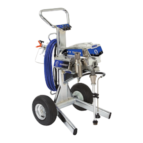
FT500 Electric Airless Sprayers
Pulvérisateurs électriques type Airless
Pulverizadores eléctricos sin aire
US Patent No. D596,707 S
- For the application of architectural paints and coatings -
- Pour l'application de peintures et revêtements architecturaux -
- Para la aplicación de pinturas y revestimientos con fines arquitectónicos -
3300psi (227 bar, 22.7 MPa) Maximum Working Pressure / Pression maximale de service 3300 lb/po² (227 bar, 22,7 MPa) / Presión máxima de
trabajo 3300psi (227 bar, 22,7 MPa)
NOTE: Important Safety Instructions
Read all warnings and instructions in this manual. Save these instructions.
NOTE: Consignes de sécurité importantes
Lire tous les avertissements et instructions qui figurent dans ce guide. Conserver ces
instructions.
NOTE: Instrucciones importantes de seguridad
Lea todas las advertencias e instrucciones de este manual. Guarde estas instrucciones.
ti3240a
313433D
EN FR ES
MODEL 826115
262458
Publicidad
Tabla de contenido
Solución de problemas

Manuales relacionados para Graco FT500


Resumen de contenidos para Graco FT500
- Página 1 Operation / Repair / Parts Fonctionnement / Réparation / Pièces Funcionamiento / Reparación/ Piezas FT500 Electric Airless Sprayers Pulvérisateurs électriques type Airless Pulverizadores eléctricos sin aire 313433D US Patent No. D596,707 S EN FR ES - For the application of architectural paints and coatings - - Pour l’application de peintures et revêtements architecturaux -...
-
Página 2: Tabla De Contenido
Repair / Réparation / Reparación ... . . 42 Warnings ....... . . 3 Solución de problemas . -
Página 3: Warnings
Warnings Warnings The following warnings are for the setup, use, grounding, maintenance and repair of this equipment. The exclamation point symbol alerts you to a general warning and the hazard symbol refers to procedure-specific risks. Refer back to these warnings. Additional, product-specific warnings may be found throughout the body of this manual where applicable. -
Página 4: Fire And Explosion Hazard
• Check hoses and parts for signs of damage. Replace any damaged hoses or parts. • This system is capable of producing 3300 psi. Use Graco replacement parts or accessories that are rated a minimum of 3300 psi. • Always engage the trigger lock when not spraying. Verify the trigger lock is functioning properly. - Página 5 Do not kink or over-bend the hose. • Do not expose the hose to temperatures or to pressures in excess of those specified by Graco. • Do not use the hose as a strength member to pull or lift the equipment.
-
Página 6: Mise En Garde
Mise en garde Mise en garde Les mises en gardes suivantes sont des mises en garde relatives à la sécurité au sujet de la configuration, l’utilisation, la mise à la terre, l’entretien et la réparation de ce matériel. Le point d’exclamation est une mise en garde générale et le symbole de danger fait référence à... - Página 7 • Cet appareil peut produire une pression de 3300 psi (22,7 MPa, 227 bars). Utiliser les pièces de rechange et les accessoires de Graco conçus pour des pressions d’au moins 3300 psi (22,7 MPa, 227 bars). • Toujours verrouiller la gâchette à chaque arrêt de la pulvérisation. Vérifier que le verrou de la gâchette fonctionne correctement.
-
Página 8: Danger De Décharge Électrique
• Ne pas emmêler ou trop tordre le flexible. • Ne pas exposer le flexible à des températures ou des pressions supérieures à celles définies par Graco. • Ne pas utiliser le flexible comme levier pour soulever ou tirer l’appareil. -
Página 9: Advertencias
Advertencias Advertencias A continuación se ofrecen advertencias relacionadas con la seguridad de la puesta en marcha, utilización, conexión a tierra, mantenimiento y reparación de este equipo. El símbolo acompañado de una exclamación le indica que se trata de una advertencia y el símbolo de peligro se refiere a un riesgo específico. -
Página 10: Peligro De Incendios Y Explosiones
Inspeccione las mangueras y las piezas en busca de signos de desgaste. Reemplace las mangueras y las piezas dañadas. • El sistema es capaz de producir una presión de 3300 psi. Utilice piezas de repuesto o accesorios Graco capaces de soportar una presión nominal mínima de 3300 psi. •... - Página 11 No utilice el equipo si está cansado o bajo los efectos de medicamentos o del alcohol. • No retuerza ni doble las mangueras. • No exponga la manguera a temperaturas o presiones que excedan las especificaciones de Graco. • No utilice la manguera para levantar o tirar del equipo. PELIGRO DE DESCARGA ELÉCTRICA Una conexión a tierra, montaje o utilización incorrectos del sistema puede causar descargas eléctricas.
-
Página 12: Component Identification / Identification Des Composants / Identificación De Los Componentes
Component Identification / Identification des composants / Identificación de los componentes Component Identification / Identification des composants / Identificación de los componentes ti13240a ti13244a English Français Español Trigger lock Loquet de sécurité Seguro del gatillo Pistolet Pistola Hose Wrap Enrouleur de flexible Enrollador de manguera Pressure control Commande de la pression... -
Página 13: Operation / Fonctionnement / Funcionamiento
Operation / Fonctionnement / Funcionamiento Operation / Fonctionnement / Funcionamiento Grounding / Mise à la terre / Conexión a tierra English Français Español The sprayer must be grounded. Grounding Ce pulvérisateur doit être raccordé à la Este pulverizador debe estar conectado reduces the risk of static and electric terre. - Página 14 Operation / Fonctionnement / Funcionamiento Ground 120V ti4297a English • Do not modify plug! If it will Power Requirements Extension Cords • If an extension cord is nec- not fit in outlet, have • 100-120V units require • Use an extension cord with essary, use a 3-wire, 12 grounded outlet installed 100-120 VAC, 50/60 Hz,...
- Página 15 Operation / Fonctionnement / Funcionamiento ti13243a ti5850a ti5851a English Pails • Do not place pail on • Grounding a metal pail: • To maintain grounding • Solvent and oil/based a nonconductive surface connect a ground wire to continuity when fluids: follow local code. such as paper or cardboard the pail by clamping one flushing or relieving...
-
Página 16: Pressure Relief Procedure / Procédure De Décompression / Procedimiento De Descompresión
Operation / Fonctionnement / Funcionamiento Pressure Relief Procedure / Procédure de décompression / Procedimiento de descompresión English Français Español To reduce risk of injury from injection, Pour réduire les risques de blessure par Para reducir el riesgo de lesiones follow this procedure whenever you are injection, observer cette procédure à... -
Página 17: Setup / Installation / Puesta En Marcha
Bien serrer. Español Conecte la manguera Conecte el otro extremo Apriete firmemente. Retire la protección sin aire Graco al de la manguera a la de la boquilla. pulverizador. pistola. Apriete firmemente. 313433D... - Página 18 Operation / Fonctionnement / Funcionamiento ti2810a Approximate Fill Level ti2810a ti13237a ti2812a English Check inlet strainer for Fill throat packing nut Turn power OFF. Plug power supply cord clogs and debris. with TSL to prevent into a properly grounded premature packing wear. electrical outlet.
- Página 19 Operation / Fonctionnement / Funcionamiento ti13222a ti13223a English Turn prime valve down. 10 Place siphon tube set in grounded metal pail partially filled with flushing fluid. Attach ground wire to pail and to true earth ground. Do 1. - 5. of Startup, page 20 to flush out storage oil shipped in sprayer.
-
Página 20: Startup / Démarrage / Puesta En Marcha
Operation / Fonctionnement / Funcionamiento Startup / Démarrage / Puesta en marcha ti13226a ti13238a ti13224a ti13225a English Turn pressure control to Turn power ON. Increase pressure to start Turn prime valve lowest pressure. motor and allow fluid horizontal.Take spray gun to circulate through drain trigger safety OFF. - Página 21 Operation / Fonctionnement / Funcionamiento ti13029a ti2714a ti2714a PAINT English Hold gun against Inspect for leaks. Do not stop Place siphon tube in paint Trigger gun again into grounded metal flushing leaks with hand or a rag! If pail. flushing pail until paint pail.
-
Página 22: Tip And Guard Assembly / Ensemble Buse Et Garde / Conjunto De Boquilla Y Portaboquillas
Operation / Fonctionnement / Funcionamiento Tip and Guard Assembly / Ensemble buse et garde / Conjunto de boquilla y portaboquillas ti13023a ti13024a ti2710a English ™ Use spray tip (A) to insert OneSeal Insert SwitchTip. Screw assembly onto gun. Tighten. (B) into guard (C). Français Mettre un joint métallique et un joint Monter la buse SwitchTip. -
Página 23: Spraying / Pulvérisation / Pulverización
Operation / Fonctionnement / Funcionamiento Spraying / Pulvérisation / Pulverización ti13224a ti13030a ti13025a English Spray test pattern. Start with pressure turned to its lowest Hold gun perpendicular, 10-12 in. from surface. Spray back setting, then gradually increase pressure gradually until and forth, overlapping by 50%. -
Página 24: Clearing Clog / Débouchage / Eliminación De Las Obstrucciones
Operation / Fonctionnement / Funcionamiento Clearing Clog / Débouchage / Eliminación de las obstrucciones ti10166a ti10166a ti13034a ti13033a ti10167a ti10167a English a.) Release trigger, put safety ON. a.) Put safety ON. b.) Rotate SwitchTip. b.) Return Switch to original position. c.) Take safety OFF. -
Página 25: Cleanup / Nettoyage / Limpieza
Operation / Fonctionnement / Funcionamiento Cleanup / Nettoyage / Limpieza ti2769a ti13228a ti13229a ti13227a English Turn power OFF and Turn pressure to lowest Put drain tube in pail. Remove guard and unplug sprayer. setting. Trigger gun to Turn prime valve down. SwitchTip. - Página 26 Operation / Fonctionnement / Funcionamiento ti13230a ti13233a ti13232a ti13223a English Remove siphon tube set Plug in sprayer. Turn Hold gun against paint Move gun to flushing pail, from paint and place in power ON. Turn prime pail. Take trigger safety hold gun against pail, flushing fluid.
- Página 27 Operation / Fonctionnement / Funcionamiento ti13222a ti13222a ti13234a ti13235a English Turn prime valve down 10 Raise siphon tube above 11 Close drain valve. Trigger 12 Open prime valve. and allow flushing fluid flushing fluid and run gun into flushing pail to to circulate for 1 to sprayer for 15 to purge fluid from hose.
- Página 28 Operation / Fonctionnement / Funcionamiento ti2783a ti2895a ti13059a English 13 Remove filters from gun and 14 If flushing with water, flush again 15 Wipe sprayer, hose and gun with sprayer, if installed. Clean and with mineral spirits, or Pump Armor, a rag soaked in water or mineral inspect.
-
Página 29: Digital Display / Affichage Numérique / Visualización Digital
Operation / Fonctionnement / Funcionamiento Digital Display / Affichage numérique / Visualización digital Operation ti2785a ti2786a ti2888a ti2786a ti2888a ti13236a English Follow Pressure Relief Plug sprayer in to The pressure is Press and hold display Procedure, page 16. grounded outlet. Turn displayed. - Página 30 Operation / Fonctionnement / Funcionamiento ti2821a ti2798a ti2827a ti2827a ti13237a ti2822a ti13238a English Turn power OFF. While pressing display Model number is button, turn power ON to displayed and then Data enter Stored Data mode. Point 1, power on time in hours, is displayed.
- Página 31 Operation / Fonctionnement / Funcionamiento ti2822a ti2795a ti2823a ti2825a ti2824a ti2824a ti13237a English Press display button to Press display button to Press display button to Press display button display Data Point 2, display Data Point 3, last display Data Point 4, again to return to Data motor on time in hours.
-
Página 32: Ultra Max Ii/St Max Ii Sprayers / Pulvérisateurs Ultra Max Ii/St Max Ii / Pulverizadores Ultra Max Ii
Operation / Fonctionnement / Funcionamiento Ultra Max II/ST Max II Sprayers / Pulvérisateurs Ultra Max II/ST Max II / Pulverizadores Ultra Max II ti7484b ti7485a ti7486c English Operation Main Menu Follow Pressure Relief, 2 Turn power ON. Pressure Short press display Short press moves to next page 16. - Página 33 Operation / Fonctionnement / Funcionamiento ti7487c English Press and hold to reset Note: LIFE displays briefly, to zero, or short press then the number of gallons display button to move sprayed above 1000 psi to Lifetime Gallons (70 bar, 7 MPa) (or Liters x 10).
- Página 34 Operation / Fonctionnement / Funcionamiento ti7489c ti7488b ti7490c English Secondary Menu Press display button and Model (e.g. U595) Short press display Follow Pressure Relief, turn power switch ON. displays for 1 second, button. Last error code page 16. S/N for 1 second, then is displayed;...
- Página 35 Operation / Fonctionnement / Funcionamiento ti7491c ti7493b English Press and hold display Change Display Units: button to clear error code Press and hold display button to zero. Short press to for 8 seconds to change move to software REV. pressure units (psi, bar, MPa) to desired units.
-
Página 36: Repair / Réparation / Reparación
Repair / Réparation / Reparación Repair / Réparation / Reparación Troubleshooting MOTOR DOES NOT OPERATE PROBLEM CAUSE SOLUTION Basic Fluid Pressure Problems Pressure control knob setting. Motor will Slowly increase pressure setting to see if not run if at minimum setting (fully motor starts. - Página 37 Repair / Réparation / Reparación LOW OR FLUCTUATING OUTPUT PROBLEM CAUSE SOLUTION Low Output For worn spray tip. Follow Pressure Relief procedure (page 16), then replace tip. See gun or tip manual. Verify pump does not continue to stroke Service pump (see page 66). when gun trigger is released.
- Página 38 Repair / Réparation / Reparación MOTOR IS HOT AND RUNS INTERMITTENTLY PROBLEM CAUSE SOLUTION Motor is hot and runs intermittently Determine if sprayer was operated at high Decrease pressure setting or increase tip size. pressure with small tips, which causes low motor RPM and excessive heat build-up.
-
Página 39: Repair / Réparation / Reparación
Repair / Réparation / Reparación Repair / Réparation / Reparación Dépannage PANNE DE MOTEUR PROBLÈME CAUSE SOLUTION Problèmes de base de pression Réglage du bouton de commande de pression. Augmenter lentement le réglage de la pression pour de fluide Le moteur ne tourne pas si le réglage est au voir si le moteur démarre. - Página 40 Repair / Réparation / Reparación DÉBIT FAIBLE OU VARIABLE PROBLÈME CAUSE SOLUTION Faible débit Pour une buse usée. Observer la procédure de décharge de la pression (voir page 16), ensuite remplacer la buse. Consulter le Guide d’utilisation du pistolet ou de la buse. Vérifier si la pompe arrête son mouvement Faire l’entretien de la pompe (voir page 66).
- Página 41 Repair / Réparation / Reparación LE MOTEUR EST CHAUD ET FONCTIONNE PAR INTERMITTENCE PROBLÈME CAUSE SOLUTION Le moteur est chaud et fonctionne Déterminer si le pulvérisateur fonctionnait sous Réduire la pression réglée ou choisir des buses par intermittence haute pression avec des buses à petit diamètre; d’un plus grand diamètre.
-
Página 42: Repair / Réparation / Reparación
Repair / Réparation / Reparación Repair / Réparation / Reparación Solución de problemas EL MOTOR NO FUNCIONA PROBLEMA CAUSA SOLUCIÓN Problemas básicos de presión de fluido Ajuste de la perilla de control de presión. El motor Aumente lentamente la presión para comprobar no funciona si la perilla está... -
Página 43: Potencia De Salida Baja O Fluctuante
Repair / Réparation / Reparación POTENCIA DE SALIDA BAJA O FLUCTUANTE PROBLEMA CAUSA SOLUCIÓN Potencia de salida baja Boquilla desgastada. Siga el procedimiento de alivio de presión (página 16), y luego cambie la boquilla. Consulte el manual de la pistola o la boquilla. Compruebe que la bomba no continúe funcionando Repare la bomba (ver página 66). -
Página 44: El Motor Está Caliente Y Funciona De Manera Intermitente
Repair / Réparation / Reparación EL MOTOR ESTÁ CALIENTE Y FUNCIONA DE MANERA INTERMITENTE PROBLEMA CAUSA SOLUCIÓN El motor está caliente y funciona Averigüe si el pulverizador se usó a alta presión Reduzca la presión o aumente el tamaño de la boquilla. de manera intermitente con boquillas pequeñas, lo cual provoca bajas RPM del motor y excesiva acumulación de calor. -
Página 45: On/Off Switch Replacement / Remplacement De L'interrupteur / Cambio Del Interruptor De Alimentación
Repair / Réparation / Reparación On/Off Switch Replacement / Remplacement de l’interrupteur / Cambio del interruptor de alimentación Removal / Retrait / Extracción Relieve pressure, page 16. Décharger la pression, voir page 16. Alivie la presión, página 16. ti13282a ti13285a ti13283a ti13284a English... - Página 46 Repair / Réparation / Reparación Installation / Installation / Instalación ti13285a ti13282a ti13286a ti13283a English Install board assembly Replace toggle boot Reconnect three wires Replace digital display, and switch. Tighten two (48f) and locking ring. to ON/OFF switch board pressure control cover bolts (48h) on small (48e).
-
Página 47: Pressure Control Repair / Réparation De La Commande De Pression / Reparación Del Control De Presión
Repair / Réparation / Reparación Pressure Control Repair / Réparation de la commande de pression / Reparación del control de presión Motor Control Board / Bloc de commande du moteur / Tablero de control del motor Relieve pressure, page 16. Décharger la pression, voir page 16. - Página 48 Repair / Réparation / Reparación Installation / Installation / Instalación ti13222a ti13222a ti13222a ti13222a ti13222a English Clean pad on rear Install motor Connect all leads Reconnect Install digital of motor control control board (48g) to motor control potentiometer display, cover (21a) board.
- Página 49 Repair / Réparation / Reparación Digital Display Messages No display does not mean sprayer is not pressurized. Relieve Pressure before repair, page 16. DISPLAY SPRAYER OPERATION INDICATION ACTION No Display Sprayer stops. Power is not applied. Loss of power Check power source. Relieve Sprayer may be pressurized.
- Página 50 Repair / Réparation / Reparación Messages de l’afficheur numérique L’absence d’affichage ne signifie pas l’absence d’une mise sous pression du pulvérisateur. Décharger la pression avant toute réparation, voir page 16. FONCTIONNEMENT AFFICHAGE DU PULVÉRISATEUR INDICATION ACTION Pas d’affichage Arrêt du pulvérisateur. Pas d’alimentation Perte de courant Vérifier la source d’alimentation électrique.
-
Página 51: Mensajes De La Pantalla Digital
Repair / Réparation / Reparación Mensajes de la pantalla digital La falta de indicación en pantalla no significa que el pulverizador no esté presurizado. Alivie la presión antes de realizar la reparación (página 16). OPERACIÓN DEL PANTALLA PULVERIZADOR INDICACIÓN ACCIÓN Sin indicación El pulverizador se detiene. - Página 52 Repair / Réparation / Reparación Pressure Control Transducer / Transducteur de commande de pression / Transductor de control de presión Removal / Retrait / Extracción Relieve Pressure, page 16. Décharger la pression, voir page 16. Alivie la presión, página 16. ti13293a ti13292a ti13282a...
- Página 53 Repair / Réparation / Reparación Installation / Installation / Instalación ti13295a ti13294a ti13292a ti13282a ti13291a English Install packing Thread transducer Install filter housing Connect lead (E) Replace digital o-ring (3) and lead plastic (15) with two to motor control display and install pressure control connector up screws (47).
- Página 54 Repair / Réparation / Reparación Pressure Adjust Potentiometer / Potentiomètre de réglage de la pression / Potenciómetro para ajuste de presión Removal / Retrait / Extracción Relieve Pressure, page 16. Décharger la pression, voir page 16. Alivie la presión, página 16. ti13296a ti13282a ti13297a...
- Página 55 Repair / Réparation / Reparación Installation / Installation / Instalación ti13296a ti13282a ti13297a English Install pressure adjust Connect potentiometer Install cover (50) with potentiometer (37), nut lead (J8 or J12) to motor four screws (12). (37a) and potentiometer board (49). See Wiring knob (11).
- Página 56 Repair / Réparation / Reparación Stored Data (Not available on all sprayers) / Stockage de données (Non offert sur tous les pulvérisateurs) / Datos almacenados (Función no disponible en todos los pulverizadores) Relieve Pressure, page 16. Décharger la pression, voir page 16. Alivie la presión, página 16.
- Página 57 Repair / Réparation / Reparación Stored Data Table / Tableau de stockage des données / Tabla de datos almacenados Data Point / Definition / Définition / Definición Point de données / English Français Español Punto de datos Number of hours power switch Nombre d’heures que l’interrupteur Cantidad de horas en que el has been ON with power applied...
-
Página 58: Drive Housing Replacement / Remplacement Du Carter / Cambio Del Alojamiento De La Transmisión
Repair / Réparation / Reparación Drive Housing Replacement / Remplacement du carter / Cambio del alojamiento de la transmisión AVISO NOTICE No deje caer el conjunto de engranajes (44) y (40) Do not drop gear cluster (44) and (40) when removing cuando quite el alojamiento de la transmisión (42). - Página 59 Repair / Réparation / Reparación ti13301a ti13300a English Remove screws (47). Pull drive housing (42) Remove gear cluster (44) off motor (54). and (40) and thrust washer (25) from drive housing (42). Français Enlever les vis (47). Retirer le carter (42) Retirer du carter (42) du moteur (54).
- Página 60 Repair / Réparation / Reparación Installation / Installation / Instalación ti13303a ti13300a ti13302a English Apply a heavy coat Install washers (8 Install washers Install thrust Push drive housing of grease to gears and 10) on back of (1 and 9) on back washer (25) (42) on motor and needle bearing...
- Página 61 Repair / Réparation / Reparación ti13300a ti13299a ti13298a English Install screws (47). Install cover (22) Install shroud (23) Install pump (41), 10. Install pump rod and screws (12). and screws (12). page 66. cover (70) with screws (12). Français Installer les vis (47). 7. Installer le Installer le Installer la pompe...
-
Página 62: Motor Replacement / Remplacement Du Moteur / Cambio Del Motor
Repair / Réparation / Reparación Motor Replacement / Remplacement du moteur / Cambio del motor AVISO NOTICE No deje caer el conjunto de engranajes (44) y (40) Do not drop gear cluster (44) and (40) when removing cuando quite el alojamiento de la transmisión (42). drive housing (42). - Página 63 Repair / Réparation / Reparación ti13304a ti13292a ti13305a English Remove screws (47) Remove screws (47) Remove screws (12) and manifold (15). and control box (48). and shroud (23). Remove screws (47) and motor (54) from frame (59). Français Enlever les vis (47) Enlever les vis (47) Enlever les vis (12) et le et le collecteur (15).
- Página 64 Repair / Réparation / Reparación Installation / Installation / Instalación ti13304a ti13304a ti13288a ti13305a English Install new motor (54) Install control housing Install manifold (15) Connect motor leads on frame (59) with screws (48) with screws (47). with screws (47). (see Wiring Diagram, (47).
- Página 65 Repair / Réparation / Reparación English Install Drive Housing Install Pump (41), (42), page 58. page 66. Français Installer le Carter (42), Installer la Pompe (41), voir page 58. voir page 66. Español Instale el alojamiento Instale la bomba (41) de la transmisión (42) (página 66).
-
Página 66: Pump Replacement / Remplacement De La Pompe / Cambio De La Bomba
Repair / Réparation / Reparación Pump Replacement / Remplacement de la pompe / Cambio de la bomba See manual 309250 for pump repair instructions. Consulter les instructions de réparation de la pompe dans le guide 309250. Consulte el manual 309250 para conocer las instrucciones de reparación de la bomba. Removal / Retrait / Extracción Relieve Pressure, page 16. - Página 67 Repair / Réparation / Reparación Installation / Installation / Instalación AVIS Si l’écrou de blocage de la pompe devait se desserrer durant le fonctionnement, les filets du carter s’endommageraient. If pump works loose, parts could break off due to force of pumping action.
- Página 68 Turn jam nut (29) Install suction tube Fill packing nut 10. Replace cover (70) to back. counter-clockwise (60) and high with Graco TSL over screws. Push until it stops. pressure hose until fluid flows cover down into Tighten jam nut (45).
-
Página 69: Parts / Pièces / Piezas
Parts / Pièces / Piezas Parts / Pièces / Piezas ti13241a 313433D... -
Página 70: Parts List
15C146 HOOK, pail, chrome 115477 SCREW, mach, torx pan HD 277941 BRACKET, shield, mount 196762 PIN, straight 15W478 LABEL, brand, FT500, front label 15B652 WASHER, suction 15W479 LABEL, brand, FT500, front top 287057 GEAR, reducer (first stage) 15W480 LABEL, brand, FT500, left side... -
Página 71: Parts / Pièces / Piezas
Parts / Pièces / Piezas Parts / Pièces / Piezas ti13242a 313433D... -
Página 72: Parts List
243271 TIP, spray, RAC 5 (517) (826115) 119452 CAP, hub PAA517 TIP, spray, RAC X (262458) 15W482 LABEL, brand 15W060 WIRE, hose wrap, frame, FT500 15W362 PIN, pivot, hose wrap ▲ Replacement Danger and Warning labels, tags, 113983 RING, retaining, ext. -
Página 73: Parts / Pièces / Piezas
Parts / Pièces / Piezas Parts / Pièces / Piezas ti13239a 313433D... -
Página 74: Parts List
Parts / Pièces / Piezas Parts List Ref. Part Description Qty. Ref. Part Description Qty. 287003 HOSE, cpld 117828 O-RING, PTFE encapsulated 117493 SCREW, mach, hex washer hd 111457 PACKING, o-ring 287905 BOX, control (826115) 111600 PIN, grooved 287907 BOX, control (262458) 117501 SCREW, mach, slot hex wash HD 277228 BOX, control 15G455 MANIFOLD, fluid... -
Página 75: Wiring Diagram / Diagramme De Câblage / Diagrama De Cableado
Wiring Diagram / Diagramme de câblage / Diagrama de cableado Wiring Diagram / Diagramme de câblage / Diagrama de cableado OTOR ti7380a 313433D... -
Página 76: Technical Data
Wiring Diagram / Diagramme de câblage / Diagrama de cableado Technical Data 100-120V, A, Hz Generator Motor HP (W) Cycles per Maximum Maximum Fluid Minimum W gallon (liter) Delivery gpm (lpm) Tip Size Outlet npsm 1, 13, 50/60 3750 3/4 (560) 620 (165) 0.60 (2.3) 0.025... -
Página 77: Datos Técnicos
Wiring Diagram / Diagramme de câblage / Diagrama de cableado Datos técnicos 100-120V, A, Hz W mínimos HP del motor Ciclos por gpm (lpm) Tamaño máximo npsm de salida del generador galón (litro) de caudal máximo de boquilla de fluido 1, 13, 50/60 3750 3/4 (560) -
Página 78: Warranty / Garantie / Garantía
Graco distributor to the original purchaser for use. With the exception of any special, extended, or limited warranty published by Graco, Graco will, for a period of twelve months from the date of sale, repair or replace any part of the equipment determined by Graco to be defective.