Tabla de contenido
Publicidad
Idiomas disponibles
Idiomas disponibles
Enlaces rápidos
T E C H N O L O G Y F O R T H E W E L D E R ´ S W O R L D .
DE Betriebsanleitung / EN Operating instructions / FR Mode d'emploi /
ES Instructivo de servicio / IT Istruzioni per I'uso
DE Roboterschweißstromquelle iROB P400/ P400 MV/ P500
EN Robot Welding Power Source iROB P400/ P400 MV/ P500
FR Source de courant pour soudage robotisé iROB P400/ P400 MV/ P500
ES Equipo de soldadura robótica iROB P400/ P400 MV/ P500
IT Generatore per saldatura Robot iROB P400/ P400 MV/ P500
www.binzel-abicor.com
Publicidad
Capítulos
Tabla de contenido

Manuales relacionados para Abicor Binzel iROB P400


Resumen de contenidos para Abicor Binzel iROB P400
- Página 1 DE Roboterschweißstromquelle iROB P400/ P400 MV/ P500 EN Robot Welding Power Source iROB P400/ P400 MV/ P500 FR Source de courant pour soudage robotisé iROB P400/ P400 MV/ P500 ES Equipo de soldadura robótica iROB P400/ P400 MV/ P500 IT Generatore per saldatura Robot iROB P400/ P400 MV/ P500...
-
Página 2: Tabla De Contenido
DE-23 Verwendete Zeichen und Symbole DE-10 Anhang DE-24 Lieferumfang DE-11 13.1 Ersatzteile DE-24 Transport DE-11 13.2 Schaltplan iROB P400 DE-26 Schaltplan iROB P400 MV Lagerung DE-11 13.3 DE-27 13.4 Schaltplan iROB P500 DE-28 Funktionsbeschreibung DE-12 13.5 Wartungsplan DE-29 Inbetriebnahme DE-13... -
Página 3: Identifikation
• iROB P400, P400 MV, P500 Der modulare Aufbau gestattet eine individuelle mechanische und elektronische Anpassung über E/A oder digitale BUS-Systeme. Die Roboterschweißstromquelle iROB darf nur mit Original ABICOR BINZEL Ersatzteilen betrieben werden. Diese Betriebsanleitung beschreibt nur die Roboterschweißstromquelle iROB. -
Página 4: Sicherheit
2 Sicherheit iROB 2 Sicherheit Dieses Kapitel vermittelt wichtige Informationen zur sicheren Bedienung des Produktes. Lesen Sie es vor der ersten Nutzung des Gerätes gründlich durch und stellen Sie sicher, dass jeder Nutzer mit dem Inhalt vertraut ist. • Lesen Sie die vorliegende Betriebsanleitung vor der ersten Nutzung sorgfältig durch. Sie vermittelt Ihnen Informationen, die für einen störungsfreien und sicheren Betrieb erforderlich sind. -
Página 5: Persönliche Schutzausrüstung (Psa) De
iROB 2 Sicherheit 2.3 Persönliche Schutzausrüstung (PSA) • Um Gefahren für den Nutzer zu vermeiden wird in dieser Anleitung das Tragen von persönlicher Schutzausrüstung (PSA) empfohlen. Sie besteht aus Schutzanzug, Schutzbrille, Atemschutzmaske Klasse P3, Schutzhandschuhen und Sicherheitsschuhen. 2.4 Warnhinweise Die folgenden Warnhinweise stehen in dieser Betriebsanleitung vor potenziell gefährlichen Arbeitsschritten. Nach abnehmendem Grad der Gefährdung geordnet, bedeuten sie: GEFAHR Bezeichnet eine unmittelbar drohende Gefahr. -
Página 6: Warn- Und Hinweisschilder De
2 Sicherheit iROB • Spülen Sie Werkstücke, die mit chlorierten Lösungsmitteln entfettet wurden, mit klarem Wasser ab. Ansonsten besteht die Gefahr der Phosgengasbildung. Stellen Sie keine chlorhaltigen Entfettungsbäder in der Nähe des Schweißplatzes auf. • Halten Sie die allgemeinen Brandschutzbestimmungen ein und entfernen Sie vor Arbeitsbeginn feuergefährliche Materialien aus der Umgebung des Schweißarbeitsplatzes. -
Página 7: Produktbeschreibung
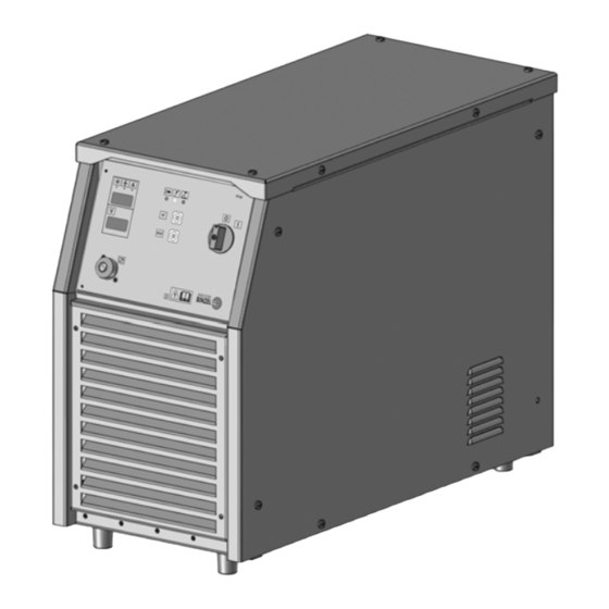
3 Produktbeschreibung 3 Produktbeschreibung 3.1 Technische Daten Abb. 1 Abmessungen Roboterschweißstromquelle iROB iROB P400 iROB P400 MV iROB P500 Netzspannung 3x400 Vac 3x400 Vac 3x400 Vac 3x320 Vac ± Netzspannnungstoleranz 15 % Netzfrequenz 50/60 Hz Netzabsicherung 25 A (400 V) - Página 8 3 Produktbeschreibung iROB iROB P400 iROB P400 MV iROB P500 Schweißstrom bei 25° C X=50 % X=60 % 500 A X=100 % 400 A 470 A Schweißstrombereich 3 - 400 A 3 - 500 A Leerlaufspannung 73 Vdc Schutzart IP23 Isolationsklasse Kühlart...
- Página 9 3 Produktbeschreibung 3.3 Typenschild Die Roboterschweißstromquelle ist am Gehäuse mit einem Typenschild wie folgt gekennzeichnet: Abb. 2 Typenschild iROB P400 Abb. 3 Typenschild iROB P400 MV DE - 9...
-
Página 10: Verwendete Zeichen Und Symbole De
3 Produktbeschreibung iROB Abb. 4 Typenschild iROB P500 Beachten Sie für alle Rückfragen folgende Angaben: • Gerätetyp, Gerätenummer 3.4 Verwendete Zeichen und Symbole In der Betriebsanleitung werden folgende Zeichen und Symbole verwendet: Symbol Beschreibung • Aufzählungssymbol für Handlungsanweisungen und Aufzählungen ... -
Página 11: Lieferumfang
Tab. 8 Roboterschweißsystem Ausrüst- und Verschleißteile separat bestellen. Bestelldaten und Identnummern der Ausrüst- und Verschleißteile entnehmen Sie den aktuellen ABICOR BINZEL Ersatz- und Verschleißteillisten. Kontakt für Beratung und Bestellung finden Sie im Internet unter www.binzel-abicor.com. 4.1 Transport Der Lieferumfang wird vor dem Versand sorgfältig geprüft und verpackt, jedoch sind Beschädigungen während des Transportes nicht auszuschließen. -
Página 12: Funktionsbeschreibung
5 Funktionsbeschreibung iROB 5 Funktionsbeschreibung iFEED MP iFEED Comfort iFEED Basic iROB iCOOL ® ® Brennerhals ABIROB Korbspulenhalter iSPOOL 12 Fernregler iCONTROL 16 Brennerhals ABIROB ® Masterantrieb MF1 Masterliner 13 Umlaufkühlgerät iCOOL 17 Brennerhals ABIROB ® Roboter Fassspule 14 Roboterschweißstromquelle 18 Brennerhals ABIROB iFEED 10 Schutzgas... -
Página 13: Inbetriebnahme
iROB 6 Inbetriebnahme 6 Inbetriebnahme GEFAHR Verletzungsgefahr durch unerwarteten Anlauf Für die gesamte Dauer von Wartungs-, Instandhaltungs-, Montage- bzw. Demontage- und Reparaturarbeiten ist folgendes zu beachten: • Schalten Sie die Stromquelle stromlos. • Ziehen Sie den Netzstecker. VORSICHT Verletzungsgefahr Erhöhte Lärmbelästigung. •... -
Página 14: Transportieren Und Aufstellen De
6 Inbetriebnahme iROB 6.1 Transportieren und Aufstellen VORSICHT Verletzungsgefahr Körperliche Schäden durch herunterfallende Geräte und Anbauteile. • Verwenden Sie zum Transportieren und Aufstellen der Roboterschweißstromquelle iROB ein geeignetes Hebezeug mit Lastaufnahmemitteln. • Vermeiden Sie ruckartiges Anheben und Absetzen. • Heben Sie die Komponenten nicht über Personen oder andere Geräte hinweg. •... -
Página 15: Roboterschweißstromquelle Irob Anschließen De
iROB 6 Inbetriebnahme 6.4 Roboterschweißstromquelle iROB anschließen HINWEIS • Beachten Sie die Betriebsanleitungen der schweißstechnischen Komponenten Umlaufkühlgerät iCOOL (optional), Drahtvorschub iFEED (optional), Fernregler iCONTROL (optional) und Schweißbrenner. Gasanschluss Anschlussbuchse Schweißstrom negativ Massekabel 12 Steuerleitung CAN-Bus Anschlussbuchse Schweißstrom positiv Kühlmittelvorlaufschlauch 13 Gasschlauch Anschlussbuchse Steuerleitung Anschluss Kühlmittelvorlauf 10 Kühlmittelrücklaufschlauch... -
Página 16: Fernregler Icontrol (Optional) De
7 Betrieb iROB 6.4.1 Fernregler iCONTROL (optional) Der Fernregler iCONTROL ist aussschließlich für die Roboterschweißstromquelle iROB konzipiert und dient der Einrichtung und Parametrierung Beachten Sie zur Montage die Angaben der Betriebsanleitung BAL.0333.0 iCONTROL. 1 Steuerleitung iCONTROL in Anschlussbuchse (8) einstecken. ... -
Página 17: Bedienelemente
iROB 7 Betrieb 7.1 Bedienelemente 7.1.1 Roboterschweißstromquelle iROB Digitalanzeige umschaltbar LED Schweißstrom Ein Taster RESET LED Stromversorgung Taster Parameterauswahl Anschluss iCONTROL LED Allgemeiner Alarm Hauptschalter Digitalanzeige Schweißspannung Abb. 7 Vorderansicht Symbol Pos. Bezeichnung Ermöglicht die Anzeige von Drahtvorschubgeschwindigkeit, empfohlene Materialstärke, Schweißstrom und Fehlercodes. -
Página 18: Außerbetriebnahme
8 Außerbetriebnahme iROB Symbol Pos. Bezeichnung Anschluss für iCONTROL. Spannung während des Schweißens/ Fehlercodes. Blindabdeckung Anschlussbuchse CAN-Bus Anschlussbuchse Schweißstrom positiv Roboterinterface RI 1000/2000/3000 Durchführung Anschlusskabel Anschlussbuchse Schweißstrom negativ Blindabdeckung Anschlussbuchse Anschlussbuchse Steuerleitung Brennerreinigungsstation Zwischenschlauchpaket Abb. 8 Rückansicht Symbol Pos. Bezeichnung Anschluss (CAN-BUS) Anschluss Steuerleitung Zwischenschlauchpaket Anschluss Schweißstrom positiv... -
Página 19: Wartung Und Reinigung
iROB 9 Wartung und Reinigung 9 Wartung und Reinigung Die Roboterschweißstromquelle iROB ist bei normalen Betriebsbedingungen wartungsfrei. Regelmäßige und dauerhafte Wartung und Reinigung sind jedoch Voraussetzung für eine lange Lebensdauer und eine einwandfreie Funktion. GEFAHR Verletzungsgefahr durch unerwarteten Anlauf Für die gesamte Dauer von Wartungs-, Instandhaltungs-, Montage- bzw. Demontage- und Reparaturarbeiten ist folgendes zu beachten: •... -
Página 20: Störungen Und Deren Behebung
10 Störungen und deren Behebung iROB 10 Störungen und deren Behebung GEFAHR Verletzungsgefahr und Geräteschäden durch unautorisierte Personen Unsachgemäße Reparaturen und Änderungen am Produkt können zu erheblichen Verletzungen und Geräteschäden führen. Die Produktgarantie erlischt bei Eingriff durch unautoristierte Personen. • Bedienungs-, Wartungs-, Reinigungs-, Störungs- und Reparaturarbeiten dürfen nur von befähigten Personen (in Deutschland siehe TRBS 1203) durchgeführt werden. -
Página 21: Demontage
iROB 11 Demontage 11 Demontage GEFAHR Verletzungsgefahr durch unerwarteten Anlauf Für die gesamte Dauer von Wartungs-, Instandhaltungs-, Montage- bzw. Demontage- und Reparaturarbeiten ist folgendes zu beachten: • Schalten Sie die Stromquelle aus. • Ziehen Sie den Netzstecker. HINWEIS • Die Demontage darf nur von befähigten Personen (in Deutschland siehe TRBS 1203) durchgeführt werden. - Página 22 Betriebsmittelhersteller vorgegebenen Sicherheitsdatenblätter. Kontaminierte Reinigungswerkzeuge (Pinsel, Lappen usw.) müssen ebenfalls entsprechend den Angaben des Betriebsmittelherstellers entsorgt werden. 12.3 Verpackungen ABICOR BINZEL hat die Transportverpackung auf das Notwendigste reduziert. Bei der Auswahl der Verpackungsmaterialien wird auf eine mögliche Wiederverwertung geachtet. DE - 22...
-
Página 23: Anhang
iROB 13 Anhang 13 Anhang 13.1 Ersatzteile 33 32 Abb. 9 Ersatzteile iROB 400/400 MV/500 Pos. Artikelbezeichnung iROB 400 iROB 400MV iROB 500 Kabelbaum Temperatursensor Hutschiene Platine Abdeckblech, oben Lüfter 60x60x15 (Buskarten) Grundplatine (Buskommunikation) DE - 23... - Página 24 13 Anhang iROB Pos. Artikelbezeichnung iROB 400 iROB 400MV iROB 500 Platine (Haupstromversorgung) Platine (Analogsignale) Platine (DPS) Hauptschalter Schaltknopf Platine Frontanzeige Abdeckkappe Einbaubuchse 7pol. Abdeckgitter, vorne Frontblech Lüfter 120x120x38 (Hauptlüfter) Diode (4Stk) Platine PFC P400 Platine PFC P400MV/P500 Platine PFC P400MV/P500 Temperatursensor Seitenblech rechts P400 Seitenblech rechts P400MV...
-
Página 25: Schaltplan Irob P400 De
13 Anhang 13.2 Schaltplan iROB P400 Abb. 10 iROB P400 DE - 25... -
Página 26: Schaltplan Irob P400 Mv De
13 Anhang iROB 13.3 Schaltplan iROB P400 MV Abb. 11 iROB P400 MV DE - 26... -
Página 27: Schaltplan Irob P500 De
iROB 13 Anhang 13.4 Schaltplan iROB P500 Abb. 12 iROB P500 DE - 27... - Página 28 13 Anhang iROB 13.5 Wartungsplan Wartungsplan Wartungs- durchzuführende ausgeführt Unterschrift/ nächste intervall Wartungsarbeiten Bemerkung Wartung Tab. 12 Wartungsplan DE - 28...
-
Página 29: Optionen
iROB 14 Optionen 14 Optionen 14.1 Roboterinterface Es stehen die Roboterinterfaces RI 1000, RI 2000 und RI 3000 zur Verfügung, die alle gängigen Robotermodelle unterstützen. 14.1.1 RI 1000 und RI 2000 Die Roboterinterfaces RI 1000 und RI 2000 sind einfache, analoge Interfaces mit einer begrenzten Anzahl analoger und digitaler Ein- und Ausgänge. - Página 30 EN-11 13.1 Spare parts EN-24 Transport EN-11 13.2 Circuit diagram iROB P400 EN-26 Storage EN-11 13.3 Circuit diagram iROB P400 MV EN-27 13.4 Circuit diagram iROB P500 EN-28 Functional description EN-12 13.5 Maintenance schedule EN-29 Putting into operation EN-13 Options...
-
Página 31: Identification
• iROB P400, P400 MV, P500 Its modular design allows an individual mechanical and electronic adjustment via I/O or digital BUS systems. The robot welding power source iROB may only be operated using original ABICOR BINZEL spare parts. These operating instructions only describe the robot welding power source iROB. -
Página 32: Safety
2 Safety iROB 2 Safety This chapter conveys significant information on safe operation of the product. Before using the system for the first time, please thoroughly read these operating instructions and make sure that every user is familiar with its contents. •... -
Página 33: Personal Protective Equipment (Ppe) En
iROB 2 Safety 2.3 Personal protective equipment (PPE) • To avoid dangers for the user, wearing personal protective equipment (PPE) is recommended in these instructions. It consists of protective clothing, safety goggles, class P3 respiratory mask, protective gloves and safety shoes. 2.4 Warnings In these operating instructions, potentially dangerous work steps are preceded by the following warnings. -
Página 34: Warning And Information Signs En
2 Safety iROB 2.6 Warning and information signs Following warning and information signs are located on the product: Symbol Meaning Read and observe operating instructions! These markings must always be legible. They may not be covered, obscured, painted over or removed. 2.7 Product-specific hazards •... -
Página 35: Product Description
3 Product description 3 Product description 3.1 Technical data Fig. 1 Dimension of the robot welding power source iROB iROB P400 iROB P400 MV iROB P500 Mains voltage 3x400 Vac 3x400 Vac 3x400 Vac 3x320 Vac ± Mains voltage tolerance... - Página 36 3 Product description iROB iROB P400 iROB P400 MV iROB P500 Welding current at 25° C X=50 % X=60 % 500 A X=100 % 400 A 470 A Welding current range 3 - 400 A 3 - 500 A Idle voltage...
-
Página 37: Nameplate
3 Product description 3.3 Nameplate The robot welding power source is labeled with a nameplate on the housing as follows: Fig. 2 Nameplate iROB P400 Fig. 3 Nameplate iROB P400 MV EN - 9... -
Página 38: Product Description
3 Product description iROB Fig. 4 Nameplate iROB P500 When making any inquiries, please remember the following information: • Device type, device number 3.4 Signs and symbols used In the operating instructions, the following signs and symbols are used: Symbol Description •... -
Página 39: Scope Of Delivery
Order the equipment parts and wear parts separately. Order data and ID numbers for the equipment parts and wear parts can be found in the current ABICOR BINZEL spare parts and wear parts lists. The contact for consulting and ordering can be found in the Internet at www.binzel-abicor.com. -
Página 40: Functional Description
5 Functional description iROB 5 Functional description iFEED MP iFEED Comfort iFEED Basic iROB iCOOL ® ® Torch neck ABIROB 12 Remote control iCONTROL 16 Torch neck ABIROB Wire basket spool holder ® Master drive MF1 iSPOOL 13 Coolant recirculator iCOOL 17 Torch neck ABIROB ®... -
Página 41: Putting Into Operation
iROB 6 Putting into operation 6 Putting into operation DANGER Risk of injury due to unexpected start-up For the entire duration of maintenance, servicing, mounting, dismounting and repair work, the following instructions must be adhered to: • Switch off the power source. •... -
Página 42: Transport And Installation En
6 Putting into operation iROB 6.1 Transport and installation CAUTION Risk of injury Physical damage due to falling devices and mounting parts. • Use an appropriate lifting tool with load securing devices for transport and installation of the iROB robot welding power source. •... -
Página 43: Connecting The Irob Robot Welding Power Source En
iROB 6 Putting into operation 6.4 Connecting the iROB robot welding power source NOTICE • Please observe the operating instructions of the welding components, coolant recirculator iCOOL (option), wire feeder iFEED (option), remote control iCONTROL (option) and welding torch. Gas connection Negative connecting socket for welding current Ground cable 12 Control lead... -
Página 44: Remote Control Icontrol (Option) En
7 Operation iROB 6.4.1 Remote control (option) iCONTROL The remote control iCONTROL is designed exclusively for the robot welding power source iROB and is used for setup and paramter setting For mounting, observe the information given in the operating instructions BAL.0333.0 iCONTROL 1 Insert control lead iCONTROL into the connecting socket (8). -
Página 45: Operating Elements En
iROB 7 Operation 7.1 Operating elements 7.1.1 iROB robot welding power source Switchable digital display Welding current On LED RESET trigger Power supply LED Parameter selection trigger Connection iCONTROL General alarm LED Main switch Welding voltage digital display Fig. 7 Front view Symbol Pos. -
Página 46: Putting Out Of Operation
8 Putting out of operation iROB Symbol Pos. Designation Connection for iCONTROL. Voltage during welding/ error codes. Dummy cover connecting socket for CAN bus Positive connecting socket for welding current robot interface RI 1000/2000/3000 Connecting cable passage Negative connecting socket for welding current Dummy cover connecting socket for torch Control lead connecting socket for cleaning station... -
Página 47: Maintenance And Cleaning
iROB 9 Maintenance and cleaning 9 Maintenance and cleaning Under normal operating conditions, the robot welding power source iROB does not require maintenance. Scheduled maintenance and cleaning, however, is a prerequisite for a long life and a trouble-free operation. DANGER Risk of injury due to unexpected start-up For the entire duration of maintenance, servicing, mounting, dismounting and repair work, the following instructions must be adhered to:... -
Página 48: Maintenance Intervals En
9 Maintenance and cleaning iROB 9.1 Maintenance intervals NOTICE • The maintenance intervals given are standard values and refer to single-shift operation. Observe the instructions given in EN 60974-4 Inspection and test during the operation of arc welding equipment and the laws and guidelines valid in the respective country. Check the following: Daily Monthly... -
Página 49: Troubleshooting
iROB 10 Troubleshooting 10 Troubleshooting DANGER Risk of injury and machine damage when handled by unauthorized persons Incorrect repair work and changes of the product may lead to significant injuries and machine damage. The product warranty will be rendered invalid if the unit is handled by unauthorized persons. •... -
Página 50: Dismounting
11 Dismounting iROB 11 Dismounting DANGER Risk of injury due to unexpected start-up For the entire duration of maintenance, servicing, mounting, dismounting and repair work, the following instructions must be adhered to: • Switch off the power source. • Pull the mains plug. NOTICE •... - Página 51 Contaminated cleaning tools (brushes, rags, etc.) must also be disposed of in accordance with the information provided by the manufacturer of the consumables. 12.3 Packaging ABICOR BINZEL has reduced the packaging for shipping to a minimum. Packaging materials are always selected with regard to their possible recycling ability. EN - 23...
-
Página 52: Appendix
13 Appendix iROB 13 Appendix 13.1 Spare parts 33 32 Fig. 9 Spare parts iROB 400/400 MV/500 Pos. Article description iROB 400 iROB 400MV iROB 500 Cable harness Temperature sensor Top hat rail Printed circuit board Cover plate, top Fan 60x60x15 (bus cards) Motherboard (bus communication) EN - 24... - Página 53 iROB 13 Appendix Pos. Article description iROB 400 iROB 400MV iROB 500 Printed circuit board (main power supply) Printed circuit board (analog signals) Printed circuit board (DPS) Main switch Button Front display printed circuit board 7-pin socket Cover grille, front Front panel Fan 120x120x38 (main fan) Diode (4x)
-
Página 54: Circuit Diagram Irob P400 En
13 Appendix iROB 13.2 Circuit diagram iROB P400 Fig. 10 iROB P400 EN - 26... -
Página 55: Circuit Diagram Irob P400 Mv En
13 Appendix 13.3 Circuit diagram iROB P400 MV Fig. 11 iROB P400 MV EN - 27... -
Página 56: Circuit Diagram Irob P500 En
13 Appendix iROB 13.4 Circuit diagram iROB P500 Fig. 12 iROB P500 EN - 28... -
Página 57: Maintenance Schedule En
iROB 13 Appendix 13.5 Maintenance schedule Maintenance schedule Maintenance Maintenance work to be Carried out Signature/remark Next interval carried out maintenance Tab. 12 Maintenance schedule EN - 29... -
Página 58: Options
14 Options iROB 14 Options 14.1 Robot interface The available robot interfaces are RI 1000, RI 2000 and RI 3000, which support all common robot models. 14.1.1 RI 1000 and RI 2000 The robot interfaces RI 1000 and RI 2000 are simple, analog interfaces with a limited number of analog and digital inputs and outputs. - Página 59 iROB 14 Options EN - 31...
- Página 60 Annexe FR-23 Matériel fourni FR-11 13.1 Pièces détachées FR-23 Transport FR-11 13.2 Schéma électrique iROB P400 FR-25 Schéma électrique iROB P400 MV Stockage FR-11 13.3 FR-26 13.4 Schéma électrique iROB P500 FR-27 Description du fonctionnement FR-12 13.5 Plan d'entretien FR-28...
-
Página 61: Déclaration De Conformité Ue
La source de courant pour soudage robotisé iROB doit être utilisée exclusivement avec des pièces détachées d’origine de ABICOR BINZEL. Le présent mode d'emploi décrit uniquement la source de courant pour soudage robotisé iROB. -
Página 62: Utilisation Conforme Aux Dispositions
2 Sécurité iROB 2 Sécurité Ce chapitre contient des informations importantes relatives à l'utilisation sûre du produit. Veuillez lire ce chapitre attentivement avant la première utilisation de l'appareil et veillez à ce que chaque utilisateur soit familier avec le contenu. •... -
Página 63: Équipement De Protection Individuel (Epi)
iROB 2 Sécurité 2.3 Équipement de protection individuel (EPI) • Afin d'éviter des risques pour l'utilisateur, il est recommandé de porter un équipement de protection individuel (EPI). L'équipement de protection individuel comprend des vêtements de protection, des lunettes de protection, un masque de protection respiratoire classe P3, des gants de protection et des chaussures de sécurité. - Página 64 2 Sécurité iROB • Toutes les vapeurs de métaux, notamment le plomb, le cadmium, le cuivre et le béryllium sont nuisibles à la santé ! Assurez-vous d'une aération ou d'une aspiration suffisante. Veillez à respecter les valeurs limites légales. • Les pièces d'œuvre dégraissées par une solution chlorée doivent être lavées à l'eau claire afin d'éviter la formation de gaz phosgène.
-
Página 65: Caractéristiques Techniques
3 Description du produit 3 Description du produit 3.1 Caractéristiques techniques Fig. 1 Cotes de la source de courant pour soudage robotisé iROB iROB P400 iROB P400 MV iROB P500 Tension de réseau 3x400 Vac 3x400 Vac 3x400 Vac 3x320 Vac ±... - Página 66 3 Description du produit iROB iROB P400 iROB P400 MV iROB P500 Courant de soudage à 25° C X=50 % X=60 % 500 A X=100 % 400 A 470 A Plage du courant de soudage 3 - 400 A 3 - 500 A...
-
Página 67: Description Du Produit
3.3 Plaque signalétique Une plaque signalétique comportant les indications suivantes se trouve sur le boîtier de la source de courant pour soudage robotisé : Fig. 2 Plaque signalétique iROB P400 Fig. 3 Plaque signalétique iROB P400 MV FR - 9... -
Página 68: Signes Et Symboles Utilisés
3 Description du produit iROB Fig. 4 Plaque signalétique iROB P500 Pour toute demande d'éclaircissements, veuillez noter les indications suivantes : • Type de l'appareil, numéro de l'appareil 3.4 Signes et symboles utilisés Les signes et symboles suivants sont utilisés dans le mode d'emploi : Symbole Description •... -
Página 69: Matériel Fourni
Commandez les pièces d'équipement et d'usure séparément. Les données nécessaires pour la commande et les références des pièces d'équipement et d’usure se trouvent dans les listes actuelles de pièces détachées et d'usure ABICOR BINZEL. Pour obtenir des conseils et pour passer vos commandes, consultez le site www.binzel-abicor.com. -
Página 70: Description Du Fonctionnement
5 Description du fonctionnement iROB 5 Description du fonctionnement iFEED MP iFEED Comfort iFEED Basic iROB iCOOL ® ® Col de cygne ABIROB 12 Télécommande iCONTROL 16 Col de cygne ABIROB Porte-bobines type ® Entraînement maître MF1 panieriSPOOL 13 Groupe de refroidissement en 17 Col de cygne ABIROB ®... -
Página 71: Mise En Service
iROB 6 Mise en service 6 Mise en service DANGER Risque de blessures en cas de mise en marche intempestive Pour toute la durée de travaux d'entretien, de maintenance, de montage, de démontage et de réparation, les points suivants doivent être respectés : •... -
Página 72: Transport Et Implantation
6 Mise en service iROB 6.1 Transport et implantation ATTENTION Risque de blessure Dommages physiques en cas de chute d'appareils et d'accessoires. • Pour le transport et l'implantation de la source de courant pour soudage robotisé iROB, utilisez un dispositif de levage approprié avec des accessoires de levage. •... - Página 73 iROB 6 Mise en service 6.4 Raccorder la source de courant pour soudage robotisé iROB AVIS • Respectez les modes d'emploi des éléments techniques de soudage du groupe de refroidissement en circuit fermé iCOOL (en option), du dévidoir iFEED (en option), de la télécommande iCONTROL (en option) et de la torche de soudage.
-
Página 74: Télécommande
7 Fonctionnement iROB 6.4.1 Télécommande (en option) iCONTROL La télécommande iCONTROL est conçue exclusivement pour la source de courant pour soudage robotisé iROB et sert au réglage et au paramétrage. Pour le montage, respectez les indications faites dans le mode d'emploi BAL.0333.0 iCONTROL. 1 Brancher le câble de commande iCONTROL dans le raccord femelle (8). -
Página 75: Éléments De Commande
iROB 7 Fonctionnement 7.1 Éléments de commande 7.1.1 Source de courant pour soudage robotisé iROB Affichage numérique commutable LED Courant de soudage Marche Touche RESET LED Alimentation électrique Touche Choix des paramètres Raccordement iCONTROL LED Alarme générale Interrupteur principal Affichage numérique tension de soudage Fig. -
Página 76: Mise Hors Service
8 Mise hors service iROB Symbole Pos. Désignation Branchement pour iCONTROL. Tension pendant le soudage / codes d'erreur. Cache d'obturation raccord femelle CAN bus Raccord femelle courant de soudage positif interface robot RI 1000/2000/3000 Passage du câble de raccordement Raccord femelle courant de soudage Cache d'obturation raccord femelle poste Raccord femelle câble de commande négatif... -
Página 77: Entretien Et Nettoyage
iROB 9 Entretien et nettoyage 9 Entretien et nettoyage Dans des conditions d'utilisation normales, la source de courant pour soudage robotisé iROB ne requiert aucun entretien. Cependant, l'entretien et le nettoyage réguliers et permanents sont indispensables pour une longue durée de vie et un fonctionnement sans problèmes. DANGER Risque de blessures en cas de mise en marche intempestive Pour toute la durée de travaux d'entretien, de maintenance, de montage, de démontage et de réparation,... - Página 78 10 Pannes et réparation iROB 10 Pannes et réparation DANGER Risque de blessures et dommages matériels causés par des personnes non autorisées Les réparations non conformes et les modifications du produit peuvent causer des blessures et des dommages matériels graves. Les effets de la garantie produit cessent en cas d'intervention de personnes non autorisées.
- Página 79 iROB 11 Démontage 11 Démontage DANGER Risque de blessures en cas de mise en marche intempestive Pour toute la durée de travaux d'entretien, de maintenance, de montage, de démontage et de réparation, les points suivants doivent être respectés : • Mettez la source de courant hors circuit. •...
-
Página 80: Produits Consommables
(pinceaux, chiffons etc.) doivent aussi être éliminés conformément aux indications du fabricant des consommables. 12.3 Emballages ABICOR BINZEL a limité l'emballage de transport au strict minimum. Lors de la sélection des matériaux d'emballage, nous veillons à leur aptitude au recyclage. FR - 22... -
Página 81: Pièces Détachées
iROB 13 Annexe 13 Annexe 13.1 Pièces détachées 33 32 Fig. 9 Pièces détachées iROB 400/400 MV/500 Pos. Désignation de l'article iROB 400 iROB 400MV iROB 500 Faisceau de câbles Capteur de température Profilé chapeau Carte Tôle de protection supérieure Ventilateur 60x60x15 (cartes bus) Carte de base (communication par bus) FR - 23... - Página 82 13 Annexe iROB Pos. Désignation de l'article iROB 400 iROB 400MV iROB 500 Carte (alimentation principale en courant) Carte (signaux analogiques) Carte (DPS) Interrupteur principal Bouton Carte affichage frontal Clapet de protection Raccord femelle encastré à 7 pôles Grille de protection, sur l'avant Tôle frontale Ventilateur 120x120x38 (ventilateur principal) Diode (4 pièces)
- Página 83 13 Annexe 13.2 Schéma électrique iROB P400 Fig. 10 iROB P400 FR - 25...
- Página 84 13 Annexe iROB 13.3 Schéma électrique iROB P400 MV Fig. 11 iROB P400 MV FR - 26...
- Página 85 iROB 13 Annexe 13.4 Schéma électrique iROB P500 Fig. 12 iROB P500 FR - 27...
-
Página 86: Plan D'entretien
13 Annexe iROB 13.5 Plan d'entretien Plan d'entretien N° Intervalle Travaux d'entretien à effectuer effectué le Signature/ Prochain d'ordre d'entretien Remarque entretien Tab. 12 Plan d'entretien FR - 28... -
Página 87: Interface Robot
iROB 14 Options 14 Options 14.1 Interface robot Les interfaces robot RI 1000, RI 2000 et RI 3000 qui prennent en charge tous les modèles courants de robots sont disponibles. 14.1.1 RI 1000 et RI 2000 Les interfaces robot RI 1000 et RI 2000 sont des interfaces analogiques simples avec un nombre limité d'entrées et de sorties analogiques et numériques. - Página 88 ES-11 13.1 Piezas de recambio ES-23 Diagrama de circuito iROB P400 Almacenamiento ES-11 13.2 ES-25 13.3 Diagrama de circuito iROB P400 MV ES-26 Descripción del funcionamiento ES-12 13.4 Diagrama de circuito iROB P500 ES-27 13.5 Plan de mantenimiento ES-28 Puesta en marcha...
-
Página 89: Identificación Es
La fuente de corriente para soldadura con robot iROB debe utilizarse únicamente con piezas de recambio originales de ABICOR BINZEL. Este manual de instrucciones describe sólo la fuente de corriente para soldadura con robot iROB. -
Página 90: Seguridad Es
2 Seguridad iROB 2 Seguridad Este capítulo transmite información importante para el manejo seguro del producto. Leerlo detenidamente antes de utilizar el aparato y asegurarse de que todos los usuarios estén familiarizados con su contenido. • Leer atentamente el presente manual de instrucciones antes de utilizar el aparato por primera vez. El mismo contiene información necesaria para una operación segura y sin fallos. -
Página 91: Equipo De Protección Individual (Epi) Es
iROB 2 Seguridad 2.3 Equipo de protección individual (EPI) • A fin de evitar riesgos para el usuario, en el presente manual se recomienda el uso de equipo de protección personal (EPI). El equipo de protección personal consiste en un traje de protección, gafas de protección, máscara antigás clase P3, guantes de protección y zapatos de seguridad. -
Página 92: Señales Indicadoras Y De Advertencia Es
2 Seguridad iROB • Observar las disposiciones generales de protección contra incendios y eliminar los materiales combustibles del lugar de trabajo de soldadura antes de comenzar a trabajar. Tener disponibles en el lugar de trabajo los elementos de protección contra incendios. 2.6 Señales indicadoras y de advertencia En el producto se encuentran las siguientes señales indicadoras y de advertencia: Símbolo... -
Página 93: Descripción Del Producto Es
3 Descripción del producto 3 Descripción del producto 3.1 Datos técnicos Fig. 1 Dimensiones de la fuente de corriente para soldadura con robotiROB iROB P400 iROB P400 MV iROB P500 Tensión de red 3x400 Vca 3x400 Vca 3x400 Vca 3x320 Vca ±... -
Página 94: Abreviaciones Es
3 Descripción del producto iROB iROB P400 iROB P400 MV iROB P500 Corriente de soldadura a 25° C X=50 % X=60 % 500 A X=100 % 400 A 470 A Rango de corriente de soldadura 3 - 400 A 3 - 500 A Tensión en vacío... -
Página 95: Descripción Del Producto
La fuente de corriente para soldadura con robot está marcada con una placa de identificación, que se encuentra en la carcasa, como sigue: Fig. 2 Placa de identificación iROB P400 Fig. 3 Placa de identificación iROB P400 MV ES - 9... -
Página 96: Signos Y Símbolos Empleados Es
3 Descripción del producto iROB Fig. 4 Placa de identificación iROB P500 Indique los datos siguientes si se pone en contacto con nosotros para cualquier pregunta: • Tipo de aparato, número de aparato 3.4 Signos y símbolos empleados En el manual de instrucciones se utilizan los siguientes signos y símbolos: Símbolo Descripción •... -
Página 97: Relación De Material Suministrado Es
Pedir accesorios y piezas de repuesto por separado. Los datos de pedido y los números de identificación de las piezas de equipo y repuesto pueden leerse en las listas de las piezas de recambio y repuesto de ABICOR BINZEL. Para informaciones sobre el contacto para asesoramiento y pedido ver www.binzel-abicor.com en Internet. -
Página 98: Descripción Del Funcionamiento Es
5 Descripción del funcionamiento iROB 5 Descripción del funcionamiento iFEED MP iFEED Comfort iFEED Basic iROB iCOOL ® ® Cuello de antorcha ABIROB Soporte de bobinas iSPOOL 12 Control remoto iCONTROL 16 Cuello de antorcha ABIROB Masterliner 13 Recirculador de refrigerante ®... -
Página 99: Puesta En Marcha Es
iROB 6 Puesta en marcha 6 Puesta en marcha ¡PELIGRO! Peligro de lesiones por arranque inesperado Observar lo siguiente durante todos los trabajos de mantenimiento, servicio, montaje, desmontaje y reparación: • Desconecte la fuente de corriente. • Desconecte el conector de red. ¡ATENCIÓN! Peligro de lesiones Alta contaminación acústica. -
Página 100: Transporte Y Posicionamiento Es
6 Puesta en marcha iROB 6.1 Transporte y posicionamiento ¡ATENCIÓN! Peligro de lesiones Daños físicos por caída de aparatos y piezas de montaje. • Utilice para el transporte y posicionamiento de la fuente de corriente de soldadura con robot iROB un equipo elevador adecuado con accesorios de elevación. -
Página 101: Conexión De La Fuente De Corriente De Soldadura Con Robot
iROB 6 Puesta en marcha 6.4 Conexión de la fuente de corriente de soldadura con robot iROB AVISO • Observar los manuales de instrucciones de los componentes técnicos de soldadura: recirculador de refrigerante iCOOL (opcional), alimentador de alambre iFEED (opcional), control remoto iCONTROL (opcional) y antorcha de soldadura. -
Página 102: Operación Es
7 Operación iROB 6.4.1 Control remoto (opcional) iCONTROL El control remoto iCONTROL ha sido diseñado exclusivamente para la fuente de corriente de soldadura con robot iROB y se utiliza para el ajuste y la parametrización Para el montaje, observar las especificaciones del manual de instrucciones BAL.0333.0 iCONTROL. 1 Introducir el cable de control iCONTROL en el enchufe de conexión (8) . -
Página 103: Elementos De Control Es
iROB 7 Operación 7.1 Elementos de control 7.1.1 Fuente de corriente de soldadura con robot iROB Indicador digital conmutable LED Corriente de soldadura enc. Pulsador RESET LED alimentación de corriente Pulsador selección de parámetros Conector iCONTROL LED Alarma general Interruptor principal Indicador digital tensión de soldadura Fig. -
Página 104: Puesta Fuera De Servicio Es
8 Puesta fuera de servicio iROB Símbolo Pos. Denominación Conector para iCONTROL. Tensión durante la soldadura / códigos de error. Tapa ciega enchufe de conexión interfaz Bus CAN Conexión de corriente de soldadura con robot RI 1000/2000/3000 Boquilla de paso cable de conexión positivo Tapa ciega enchufe de conexión estación Enchufe de conexión del cable de control... -
Página 105: Mantenimiento Y Limpieza Es
iROB 9 Mantenimiento y limpieza 9 Mantenimiento y limpieza En condiciones normales de servicio, la fuente de corriente de soldadura con robot iROB no requiere mantenimiento. Sin embargo, el mantenimiento y la limpieza regulares y duraderos son una condición para una larga vida útil y un funcionamiento perfecto. -
Página 106: Averías Y Su Eliminación Es
10 Averías y su eliminación iROB 10 Averías y su eliminación ¡PELIGRO! Riesgo de lesiones y daños en el aparato por personas no autorizadas Reparación y modificaciones inapropiadas en el producto pueden conducir a lesiones importantes daños en el aparato. La garantía del producto se extingue con la intervención de personas no autorizadas. -
Página 107: Desmontaje Es
iROB 11 Desmontaje 11 Desmontaje ¡PELIGRO! Peligro de lesiones por arranque inesperado Observar lo siguiente durante todos los trabajos de mantenimiento, servicio, montaje, desmontaje y reparación: • Desconecte la fuente de corriente. • Desconecte el conector de red. AVISO • El desmontaje sólo debe realizarse por personal capacitado (en Alemania, véase TRBS 1203). •... -
Página 108: Materiales Es
(pinceles, paños, etc.) también deben eliminarse según las indicaciones del fabricante de los combustibles. 12.3 Embalajes ABICOR BINZEL ha reducido el embalaje de transporte a un mínimo necesario. Al seleccionar los materiales de embalaje, se tiene en cuenta un posible reciclaje. ES - 22... -
Página 109: Anexo Es
iROB 13 Anexo 13 Anexo 13.1 Piezas de recambio 33 32 Fig. 9 Piezas de recambio iROB 400/400 MV/500 Pos. Denominación del artículo iROB 400 iROB 400MV iROB 500 Arnés de cables Sensor de temperatura Riel de montaje Placa Chapa de cubierta, arriba Ventilador 60x60x15 (placas de bus) Placa madre (comunicación del bus) ES - 23... -
Página 110: Denominación Del Artículo
13 Anexo iROB Pos. Denominación del artículo iROB 400 iROB 400MV iROB 500 Placa (fuente de alimentación principal) Placa (señales analógicas) Placa (DPS) Interruptor principal Pulsador Placa indicador frontal Tapa cubierta Conector hembra integrado 7 pol. Rejilla de cubierta, frontal Placa frontal montada Ventilador 120x120x38 (ventilador principal) Diodos (4 unidades) -
Página 111: Diagrama De Circuito Irob P400 Es
13 Anexo 13.2 Diagrama de circuito iROB P400 Fig. 10 iROB P400 ES - 25... -
Página 112: Diagrama De Circuito Irob P400 Mv Es
13 Anexo iROB 13.3 Diagrama de circuito iROB P400 MV Fig. 11 iROB P400 MV ES - 26... -
Página 113: Diagrama De Circuito Irob P500 Es
iROB 13 Anexo 13.4 Diagrama de circuito iROB P500 Fig. 12 iROB P500 ES - 27... -
Página 114: Plan De Mantenimiento Es
13 Anexo iROB 13.5 Plan de mantenimiento Plan de mantenimiento Nº de Intervalo de Trabajos de mantenimiento a Realizado el Firma/nota Próximo orden mantenimiento realizar mantenimiento Tab. 12 Plan de mantenimiento ES - 28... -
Página 115: Opciones
iROB 14 Opciones 14 Opciones 14.1 Interfaz con robot Se dispone de las interfaces de robot RI 1000, RI 2000 y RI 3000, las cuales son compatibles con todos los modelos de robots de uso corriente. 14.1.1 RI 1000 y RI 2000 Las interfaces de robot RI 1000 y RI 2000 son sencillas interfaces analógicas con un número limitado de entradas y salidas, analógicas y digitales. - Página 116 IT-10 Allegato IT-23 Dotazione IT-11 13.1 Ricambi IT-23 Trasporto IT-11 13.2 Schema elettrico iROB P400 IT-25 Schema elettrico iROB P400 MV Stoccaggio IT-11 13.3 IT-26 13.4 Schema elettrico iROB P500 IT-27 Descrizione delle funzioni IT-12 13.5 Piano di manutenzione IT-28...
-
Página 117: Identificazione
La struttura modulare consente un adeguamento meccanico ed elettronico personalizzato mediante ingresso/uscita oppure sistemi BUS digitali. L’apparecchio robotizzato per saldatura iROB si deve usare solo con parti di ricambio originali di ABICOR BINZEL. Le presenti istruzioni per l’uso descrivono solo l’apparecchio robotizzato per saldatura iROB. -
Página 118: Sicurezza
2 Sicurezza iROB 2 Sicurezza Il presente capitolo trasmette informazioni importanti per l’utilizzo sicuro del prodotto. Leggerlo attentamente prima del primo utilizzo dell’apparecchio e accertarsi che ogni operatore abbia familiarità con il relativo contenuto. • Leggere attentamente il presente manuale d’uso prima del primo utilizzo Esso trasmette le informazioni necessarie per un funzionamento sicuro e regolare. -
Página 119: Dispositivi Di Protezione Individuale (Dpi)
iROB 2 Sicurezza 2.3 Dispositivi di protezione individuale (DPI) • Onde evitare pericoli per l’operatore, nel presente manuale si raccomanda di indossa i dispositivi di protezione individuale (DPI). Essi consistono in tuta da lavoro, occhiali protettivi, maschera per la protezione delle vie respiratorie della classe P3, guanti di protezione e scarpe antinfortunistiche. 2.4 Segnali di avvertenza e pericolo Nel presente manuale, i seguenti segnali di avvertenza e pericolo accompagnano fasi di lavoro potenzialmente pericolose. -
Página 120: Pericoli Specifici Del Prodotto
2 Sicurezza iROB 2.6 Segnali di avvertenza e pericolo Sul prodotto si trovano i seguenti segnali di avvertenza e pericolo: Simbolo Significato Leggere e rispettare le istruzioni per l’uso! Queste marcature devono essere sempre leggibili. Non devono essere coperte da adesivi, scritte o altro ancora, né... -
Página 121: Descrizione Del Prodotto
3 Descrizione del prodotto 3 Descrizione del prodotto 3.1 Dati tecnici Fig. 1 Dimensioni apparecchio robotizzato per la saldatura iROB iROB P400 iROB P400 MV iROB P500 Tensione di rete 3x400 Vac 3x400 Vac 3x400 Vac 3x320 Vac ±... -
Página 122: Abbreviazioni
3 Descrizione del prodotto iROB iROB P400 iROB P400 MV iROB P500 Corrente di saldatura a 25° C X=50 % X=60 % 500 A X=100 % 400 A 470 A Intervallo corrente di saldatura 3 - 400 A 3 - 500 A... -
Página 123: Descrizione Del Prodotto
3 Descrizione del prodotto 3.3 Targhetta L’apparecchio robotizzato per saldatura è contrassegnato sulla custodia con una targhetta di prodotto nel modo seguente: Fig. 2 Targhetta iROB P400 Fig. 3 Targhetta iROB P400 MV IT - 9... -
Página 124: Segni E Simboli Utilizzati
3 Descrizione del prodotto iROB Fig. 4 Targhetta iROB P500 Si prega di indicare i dati seguenti in tutte le eventuali domande: • tipo e numero di apparecchio 3.4 Segni e simboli utilizzati In queste istruzioni per l’uso vengono utilizzati i seguenti segni e simboli: Simbol Descrizione •... -
Página 125: Dotazione
Ordinare separatamente i componenti in dotazione e le parti soggette a usura. I dati dell’ordine e i numeri identificativi dei componenti in dotazione e delle parti soggette a usura si trovano nelle liste delle parti di ricambio e soggette a usura ABICOR BINZEL. I contatti per consulenze e ordini si trovano in internet alla pagina www.binzel-abicor.com. -
Página 126: Descrizione Delle Funzioni
5 Descrizione delle funzioni iROB 5 Descrizione delle funzioni iFEED MP iFEED Comfort iFEED Basic iROB iCOOL ® ® Lancia ABIROB 12 Regolatore a distanza iCONTROL 16 Lancia ABIROB Supporto bobina con cestello ® Azionamento master MF1 iSPOOL 13 Apparecchio di raffreddamento in 17 Lancia ABIROB ®... -
Página 127: Messa In Funzione
iROB 6 Messa in funzione 6 Messa in funzione PERICOLO Pericolo di lesioni dovuto all’avvio involontario Per l’intera durata dei lavori di manutenzione, montaggio e smontaggio e riparazione, osservare le seguenti indicazioni: • Spegnere l’alimentazione elettrica. • Staccare la spina. ATTENZIONE Pericolo di lesioni Elevato inquinamento acustico. -
Página 128: Trasporto E Installazione
6 Messa in funzione iROB 6.1 Trasporto e installazione ATTENZIONE Pericolo di lesioni Danni fisici provocati dalla caduta di apparecchi e parti di montaggio. • Per il trasporto e l’installazione dell’apparecchio robotizzato per saldatura iROB, usare un mezzo di sollevamento idoneo con dispositivi per il fissaggio del carico. •... - Página 129 iROB 6 Messa in funzione 6.4 Collegamento dell’apparecchio robotizzato per saldatura iROB AVVISO • Osservare le istruzioni per l’uso dei componenti di saldatura dell’apparecchio di raffreddamento in ricircolo iCOOL (opzionale), del dispositivo di avanzamento filo iFEED (opzionale), del regolatore a distanza iCONTROL (opzionale) e della torcia di saldatura.
-
Página 130: Regolatore A Distanza
7 Funzionamento iROB 6.4.1 Regolatore a distanza (opzionale) iCONTROL Il regolatore a distanza iCONTROL è concepito esclusivamente per l’apparecchio robotizzato per saldatura iROB e serve per la configurazione e la parametrizzazione Per il montaggio, osservare quanto riportato nel manuale BAL.0333.0 iCONTROL. 1 Inserire la linea di comando iCONTROL nel connettore femmina (8). -
Página 131: Elementi Di Comando
iROB 7 Funzionamento 7.1 Elementi di comando 7.1.1 Apparecchio robotizzato per saldatura iROB Display digitale commutabile Corrente di saldatura LED on Tasto RESET Alimentazione di corrente LED Tasto selezione parametri Attacco iCONTROL Allarme generale LED Interruttore principale Display digitale tensione di saldatura Fig. -
Página 132: Messa Fuori Servizio
8 Messa fuori servizio iROB Simbolo Pos. Denominazione Attacco per iCONTROL. Tensione durante la saldatura/codice di errore. Copertura connettore femmina interfaccia Bus CAN Connettore femmina corrente di saldatura robot RI 1000/2000/3000 Esecuzione cavo di collegamento positivo Copertura connettore femmina stazione di Connettore femmina linea di comando Connettore femmina corrente di saldatura pulizia torcia... -
Página 133: Pulizia E Manutenzione
iROB 9 Pulizia e manutenzione 9 Pulizia e manutenzione L’apparecchio robotizzato per saldatura iROB non richiede manutenzione in condizioni d’uso normali. La manutenzione e pulizia regolari e costanti costituiscono, tuttavia, il presupposto per una lunga durata utile e un funzionamento perfetto. PERICOLO Pericolo di lesioni dovuto all’avvio involontario Per l’intera durata dei lavori di manutenzione, montaggio e smontaggio e riparazione, osservare le... -
Página 134: Anomalie E Rimedi
10 Anomalie e rimedi iROB 10 Anomalie e rimedi PERICOLO Pericolo di lesioni e danni all’apparecchio da parte di persone non autorizzate Le riparazioni e modifiche inadeguate del prodotto, possono provocare lesioni gravi e danni all’apparecchio. La garanzia sul prodotto perde di validità in caso di interventi da parte di persone non autorizzate. -
Página 135: Smontaggio
iROB 11 Smontaggio 11 Smontaggio PERICOLO Pericolo di lesioni dovuto all’avvio involontario Per l’intera durata dei lavori di manutenzione, montaggio e smontaggio e riparazione, osservare le seguenti indicazioni: • Spegnere l’alimentazione elettrica. • Staccare la spina. AVVISO • I lavori di smontaggio devono essere eseguiti solo da persone autorizzate (in Germania, si veda TRBS 1203). -
Página 136: Smaltimento
Strumenti contaminati utilizzati per la pulizia (pennello, stracci, ecc.) devono anch’essi essere trattati in conformità alle indicazioni del costruttore dei materiali. 12.3 Imballaggi ABICOR BINZEL ha ridotto all’essenziale l’imballo per il trasporto. Nella scelta del materiale per l’imballo si è prestata attenzione a un possibile riutilizzo. IT - 22... -
Página 137: Allegato
iROB 13 Allegato 13 Allegato 13.1 Ricambi 33 32 Fig. 9 Ricambi iROB 400/400 MV/500 Pos. Nome articolo iROB 400 iROB 400MV iROB 500 Fascio cavi Sensore di temperatura Guida Scheda Lamiera di copertura, in alto Ventola 60x60x15 (schede bus) Scheda di base (comunicazione bus) IT - 23... - Página 138 13 Allegato iROB Pos. Nome articolo iROB 400 iROB 400MV iROB 500 Scheda (alimentazione elettrica principale) Scheda (segnali analogici) Scheda (DPS) Interruttore principale Pulsante di accensione Scheda display frontale Tappo chiusura Connettore femm. 7 poli Griglia di copertura, avanti Lamiera frontale Ventola 120x120x38 (ventola principale) Diodi (4 pz.) Scheda PFC P400...
-
Página 139: Schema Elettrico Irob P400
13 Allegato 13.2 Schema elettrico iROB P400 Fig. 10 iROB P400 IT - 25... -
Página 140: Schema Elettrico Irob P400 Mv
13 Allegato iROB 13.3 Schema elettrico iROB P400 MV Fig. 11 iROB P400 MV IT - 26... -
Página 141: Schema Elettrico Irob P500
iROB 13 Allegato 13.4 Schema elettrico iROB P500 Fig. 12 iROB P500 IT - 27... -
Página 142: Piano Di Manutenzione
13 Allegato iROB 13.5 Piano di manutenzione Piano di manutenzione Numero Intervallo di Lavori di manutenzione da Eseguiti il Firma/annotazione Prossima prog. manutenzione eseguire manutenzione Tab. 12 Piano di manutenzione IT - 28... -
Página 143: Opzioni
iROB 14 Opzioni 14 Opzioni 14.1 interfaccia robot Sono disponibili le interfacce robot RI 1000, RI 2000 e RI 3000 che supportano tutti i modelli di robot correnti. 14.1.1 RI 1000 e RI 2000 Le interfacce robot RI 1000 e RI 2000 sono interfacce semplici, analogiche con un numero limitato di entrate e uscite analogiche e digitali. - Página 144 T E C H N O L O G Y F O R T H E W E L D E R ´ S W O R L D . Alexander Binzel Schweisstechnik GmbH & Co.KG Postfach 10 01 53 • D–35331 Giessen Tel.: ++49 (0) 64 08 / 59–0 Fax:...