
Manuales relacionados para Sirona ORTHOPHOS XG 5/Ceph


Resumen de contenidos para Sirona ORTHOPHOS XG 5/Ceph
- Página 1 kÉì=~ÄW kÉï=ëáåÅÉW MTKOMNO kçìîÉ~ì=ÇÉéìáëW kìÉîç=ÇÉëÇÉW loqelmelp=ud=R=L=`ÉéÜ loqelmelp=ud=P fåëí~ää~íáçåëîçê~ìëëÉíòìåÖÉå= fåëí~ää~íáçå=oÉèìáêÉãÉåíë= `çåÇáíáçåë=ÇÛáåëí~ää~íáçå= oÉèìáëáíçë=ÇÉ=áåëí~ä~Åáμå=...
-
Página 2: Tabla De Contenido
ORTHOPHOS XG Sirona Dental Systems GmbH Interference with electromedical devices by radio tele- ACHTUNG ATTENTION phones: Die einwandfreie Abschirmung des Raumes und des Stand- Proper shielding of room and operator position is essential. To guarantee the operational safety of electromedical de- ortes der Bedienperson ist unbedingt erforderlich. - Página 3 Sirona Dental Systems GmbH ORTHOPHOS XG Interferencia en aparatos electromédicos por radioteléfo- ATTENTION ATENCIÓN nos: Perturbation d'appareils électro-médicaux par radiotélé- Le blindage correct de la salle et de l'emplacement de l'opé- Es imprescindible el blindaje correcto de la sala y del empla- Para garantizar la seguridad funcional de aparatos electro- phones: Pour garantir la sécurité...
-
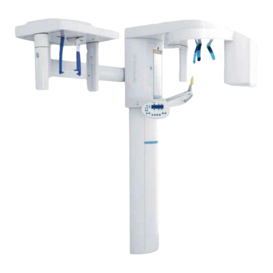
Página 5: Installationsmöglichkeiten
Installationsmöglichkeiten Possibilities of Installation Possibilités d'installation Posibilidades de instalación ® ® ® ORTHOPHOS XG ohne Fernauslö- ORTHOPHOS XG without remote con- ORTHOPHOS XG® sans déclenchement ORTHOPHOS XG sin disparo a distan- sung mit Auslösetaster am Spiralkabel im trol with release button on coiled cable in à... - Página 6 Befestigungsbügel Mindest-Raumhöhe 2100mm Wall bracket Minimum height of room 82 5/8” (2100mm) 16 1/2” Support mural Hauteur minimale 2100mm Separador mural Altura mínima del techo 2100mm Säulenmitte des Gerätes Center of Fernauslösung unit's column Remote Control Centre de la Télécommande colonne Telemando Centro de la...
-
Página 7: Bauseitige Installation Prinzipdarstellung
Bauseitige Installation Principle of On-site Installation Installation sur le site Instalación en la obra Prinzipdarstellung Schéma de principe Descripción de principio Installationsrohr für Fernauslösung Conduit for remote control Tube d'installation p.télécommande Tubo de instalación para telemando Bei Installation der abgeschirmten Steu- For concealed installation of the En cas d'installation du câble de commande Para la instalación del cable de mando... - Página 8 Säulenmitte des Gerätes Center of unit's column Centre de la colonne Centro de la Fernauslösung columna Remote Control Télécommande Telemando N PE 1500 - 2000 59 - 79” Not-Aus Schalter 1200 - 1500 Emergency stop switch 47 - 59” Le bouton d’arrêt d’urgence Interruptor de desconexión de emergencia * Mit Fernauslösung muss der Not-Aus Schalter im Abstand von <...
-
Página 9: Not-Aus-Schalter (Wenn Gesetzlich Vorgeschrieben)
Not-Aus-Schalter Emergency Stop Arrêt d’urgence Desconexión de emergencia (wenn gesetzlich vorgeschrieben) (if required by law) (lorsque prescription légale) (caso necesario por ley) Not-Aus Schalter in die Netzleitung instal- Install the emergency stop switch in the Installer l’interrupteur d’arrêt d’urgence Instale el interruptor de desconexión de lieren. - Página 10 Netzwerk Netzwerk Network Network Réseau Réseau ORTHOPHOS Lichtwellenleiter SC → Ethernetleitung RJ45 SC Fiber optic cable SC → RJ45 Ethernet cable → Câble à fibre optique SC câble Ethernet RJ45 → Cable de fibra óptica SC Cable ethernet RJ45 Mediakonverter * Der Mediakonverter ist notwendig wenn kein Lichtwellenleiternetzwerk mit SC-Stecker vorhanden ist.
-
Página 11: Bauseitige Installation Für Pc/Netzwerke
Bauseitige Installation für PC/ On-site Installation for PC/ Installation pour l'ordinateur/ Instalación en la obra para PC/ Netzwerke Networks Réseaux Redes Länge des beim Mediakonverter mitge- Length of patch cable supplied with Longueur du câble de patch fourni avec le Longitud del cable de patch suministrado lieferten Patchkabels: 5m media converter: 5 m. -
Página 12: For Usa And Canada
For USA and Canada 3x AWG see chart Distribution panel with an overcurrent circuit breaker rated for 25A Ground Distributor box Minimum Wire run distance in feet wire size 75 100 125 No.12 AWG No.10 AWG No.8 AWG Wire Size for Power Line •... -
Página 13: Orthophos Xg 5, Orthophos Xg
ORTHOPHOS XG 5, ORTHOPHOS XG 3 1:20 1950 76 3/4” 2249 ORTHOPHOS 88 1/2” Alternative Befestigung, nur wenn anschrauben am Fußboden nicht möglich ist. Bügel separat bestellen. Alternative fastening only to be used if screw in floor is not possible. Please order bracket separately. - Página 14 ORTHOPHOS XG 5, auf Standfuß on Floor stand sur Pied ORTHOPHOS XG 3 1:20 en el Pedestal Standfuß: Alternative Befestigung, nur wenn anschrauben an der Wand nicht möglich ist. Standfuß separat bestellen. Floor stand: Alternative fastening to be used only if a screw cannot be inserted in the wall.
-
Página 15: Dimensions, Technical Data Orthophos Xg 5, Orthophos Xg 3 1:20
ORTHOPHOS XG 5 Ceph Ceph links Ceph left Ceph gauche 1:20 Ceph izquierdo 1950 76 3/4” 2249 ORTHOPHOS 88 1/2” Alternative Befestigung, nur wenn anschrauben am Fußboden nicht möglich ist. Bügel separat bestellen. Alternative fastening only to be used if screw in floor is not possible. -
Página 16: Technische Daten
Technische Daten Abmessungen der Verpackung ORTHOPHOS XG 199cm x 69cm x 122cm (78 3/8“ x 27 1/8“ x 48“) Cephalometer 175cm x 78cm x 73cm (68 7/8“ x 30 3/4“ x 28 3/4“) Standfuß 114cm x 105cm x 22cm (56 3/4“ x 41 3/8“ x 8 5/8“) Gewicht einschl. -
Página 17: Caractéristiques Techniques
Caractéristiques techniques Dimensions de l’emballage ORTHOPHOS XG 199cm x 69cm x 122cm (78 3/8“ x 27 1/8“ x 48“) Céphalomètre 175cm x 78cm x 73cm (68 7/8“ x 30 3/4“ x 28 3/4“) Pied 114cm x 105cm x 22cm (56 3/4“ x 41 3/8“ x 8 5/8“) Poids avec / sans emballage ORTHOPHOS XG... -
Página 18: Elektromagnetische Verträglichkeit
Zweiter Schutzleiter 1,5 mm 58 72 648 D3285 • Das GERÄT darf nur mit dem von Sirona freigegebenen Zubehör und Ersatzteilen betrieben werden. Nicht freigegebenes Zu- behör und Ersatzteile können zu einer erhöhten Aussendung oder zu einer reduzierten Störfestigkeit führen. •... -
Página 19: Störfestigkeit
Störfestigkeit Das GERÄT ist für den Betrieb in der unten angegebenen elektromagnetischen Umgebung bestimmt. Der Kunde oder der Anwender des GERÄTS sollte sicherstellen, dass es in einer solchen Umgebung benutzt wird. Störfestigkeits- IEC 60601-1-2 Prüfpegel Übereinstimmungspegel Elektromagnetische Umgebung – Prüfungen Leitlinien Entladung statischer Elek- ±... - Página 20 Störfestigkeits- IEC 60601-1-2 Prüfpegel Übereinstimmungspegel Elektromagnetische Umgebung – Prüfungen Leitlinien Gestrahlte HF-Störgrößen 3V/m 1 2 , IEC 61000-4-3 80MHz bis 800MHz bei 80MHz bis 800MHz 3V/m 2 3 , 800MHz bis 2,5GHz bei 800MHz bis 2,5GHz als der Nennleistung des Senders in Watt (W) gemäß...
-
Página 21: Schutzabstände
Schutzabstände Empfohlene Schutzabstände zwischen tragbaren und mobilen HF-Kommunikationsgeräten und dem GERÄT GERÄT ist für den Betrieb in einer elektromagnetischen Umgebung bestimmt, in der gestrahlte HF-Störgrößen kontrolliert GERÄT werden. Der Kunde oder der Anwender des kann helfen elektromagnetische Störungen dadurch zu verhindern, dass er GERÄT Mindestabstände zwischen tragbaren und mobilen HF-Kommunikationseinrichtungen (Sendern) und dem –... -
Página 22: Electromagnetic Compatibility Accessories
2nd protective ground wire, 1.5mm 58 72 648 D3285 • The UNIT may be operated only with accessories and spare parts approved by Sirona. Unapproved accessories and spare parts may lead to an increased emission of or a reduced immunity to interference. •... -
Página 23: Immunity To Interference
Immunity to interference The UNIT is intended for operation in the electromagnetic environment specified below. The customer or user of the UNIT should make sure that it is used in such an environment. Immunity interference IEC 60601-1-2 test level Conformance level Electromagnetic environment guide- tests lines... - Página 24 Immunity interference IEC 60601-1-2 test level Conformance level Electromagnetic environment guide- tests lines Radiated HF interference 3V/m 1 2 , IEC 61000-4-3 80MHz to 800MHz at 80MHz to 800MHz 3V/m 2 3 , 800MHz to 2.5GHz at 800MHz to 2.5GHz where is the nominal transmitter out- put in watts (W) specified by the trans-...
-
Página 25: Working Clearances
Working clearances Recommended working clearances between portable and mobile HF communication devices and the UNIT UNIT is intended for operation in an electromagnetic environment, where radiated HF interference is checked. The customer UNIT or the user of the can help prevent electromagnetic interference by duly observing the minimum distances between portable UNIT and/or mobile HF communication devices (transmitters) and the . -
Página 26: Compatibilité Électromagnétique
58 72 648 D3285 • L'APPAREIL doit uniquement être utilisé avec les accessoires et les pièces de rechange validées par Sirona. Les accessoires et pièces de rechange non validés peuvent provoquer une augmentation des émissions ou une réduction de la résistance aux perturbations. -
Página 27: Résistance Au Parasitage
Résistance au parasitage L'APPAREIL est prévu pour le fonctionnement dans l'environnement électromagnétique décrit ci-après. Le client ou l'utilisateur de l'APPAREIL doit garantir qu'il sera utilisé dans un environnement tel que celui décrit. Contrôles de résistance CEI 60601-1-2 Niveau de Niveau de conformité Directives d'environnement électro- au parasitage contrôle... - Página 28 Contrôles de résistance CEI 60601-1-2 Niveau de Niveau de conformité Directives d'environnement électro- au parasitage contrôle magnétique Grandeurs de perturbation 3V/m 1 2 , HF rayonnées 80MHz à 800MHz pour 80MHz à 800MHz CEI 61000-4-3 3V/m 2 3 , 800MHz à 2,5GHz pour 800MHz à...
-
Página 29: Distances De Protection
Distances de protection Distances de protection recommandées entre des appareils de communication HF portables et mobiles et l'APPAREIL. APPAREIL est prévu pour une utilisation dans un environnement électromagnétique dans lequel les grandeurs perturbatrices APPAREIL HF rayonnées sont contrôlées. Le client ou l'utilisateur de l' peut contribuer à... -
Página 30: Compatibilidad Electromagnética
58 72 648 D3285 1,5mm • El EQUIPO solamente puede utilizarse con los accesorios y los repuestos autorizados de Sirona. Los accesorios y los repuestos no autorizados pueden aumentar las emisiones o reducir la resistencia a las interferencias. • El EQUIPO no debería utilizarse muy cerca de otros equipos. Si no se puede evitar, se deberá observar si el EQUIPO funciona de la forma adecuada. -
Página 31: Resistencia A Interferencias
Resistencia a interferencias El EQUIPO está concebido para funcionar en el entorno electromagnético indicado. El cliente o el usuario del EQUIPO debería asegurar que se utilizará siempre en un entorno como éste. Comprobaciones de Nivel de ensayo de Nivel de conformidad Directrices sobre entornos resistencia a conformidad con... - Página 32 Comprobaciones de Nivel de ensayo de Nivel de conformidad Directrices sobre entornos resistencia a conformidad con electromagnéticos interferencias IEC 60601-1-2 Inmunidad a los campos 3 V/m 1 2 , electromagnéticos de 80 MHz a 800 MHz de 80 MHz a 800 MHz radiados 3 V/m 2 3 ,...
-
Página 33: Distancias De Protección
Distancias de protección Distancias de protección recomendadas entre los equipos de comunicación móviles y portátiles por alta frecuencia y el EQUIPO EQUIPO está concebido para funcionar en un entorno electromagnético en el que se comprueba inmunidad a los campos EQUIPO electromagnéticos radiados. - Página 34 ûåÇÉêìåÖÉå=áã=wìÖÉ=íÉÅÜåáëÅÜÉê=tÉáíÉêÉåíïáÅâäìåÖ=îçêÄÉÜ~äíÉåK tÉ=êÉëÉêîÉ=íÜÉ=êáÖÜí=íç=ã~âÉ=~åó=~äíÉê~íáçåë=ïÜáÅÜ=ã~ó=ÄÉ=êÉèìáêÉÇ=ÇìÉ=íç=íÉÅÜåáÅ~ä=áãéêçîÉãÉåíëK pçìë=ê¨ëÉêîÉ=ÇÉ=ãçÇáÑáÅ~íáçåë=ÇìÉë=~ì=éêçÖê≠ë=íÉÅÜåáèìÉK oÉëÉêî~Ççë=äçë=ÇÉêÉÅÜçë=ÇÉ=ãçÇáÑáÅ~Åáμå=Éå=îáêíìÇ=ÇÉä=éêçÖêÉëç=í¨ÅåáÅçK péê~ÅÜÉW=ÇÉìíëÅÜI=ÉåÖäáëÅÜI=Ñê~åò∏ëáëÅÜI=ëé~åáëÅÜ mêáåíÉÇ=áå=dÉêã~åó a=PPROKMONKMNKNPKMV===MTKOMNO ûKJkêKW= NNR=RUR fãéêáã¨=Éå=^ääÉã~ÖåÉ páêçå~=aÉåí~ä=póëíÉãë=dãÄe áå=íÜÉ=rp^W c~Äêáâëíê~≈É=PN páêçå~=aÉåí~ä=póëíÉãë=ii` _ÉëíÉääJkêK RV=PU=PQM=a=PPRO SQSOR=_ÉåëÜÉáã QUPR=páêçå~=aêáîÉI=pìáíÉ=NMM lêÇÉê=kç dÉêã~åó `Ü~êäçííÉI=k`=OUOTP kçK=ÇÉ=ÅÇÉK ïïïKëáêçå~KÅçã kç=ÇÉ=éÉÇáÇç...