
Manuales relacionados para Nogueira FTN-2500


Resumen de contenidos para Nogueira FTN-2500
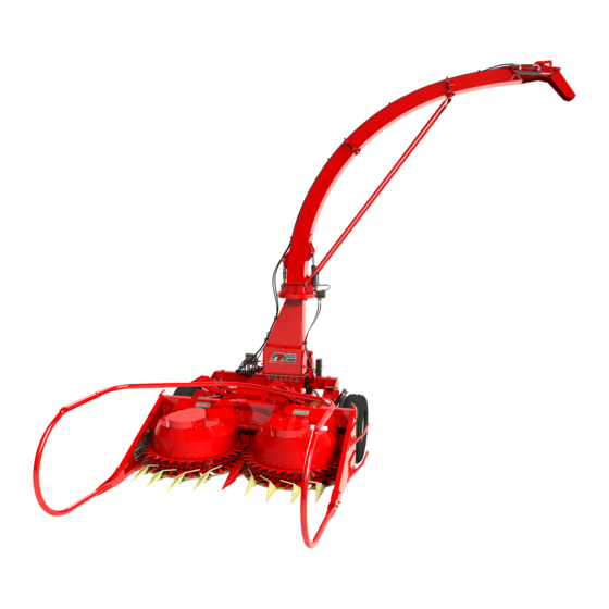
- Página 1 FTN-2500 COSECHADORA DE FORRAJE FORAGE HARVESTER M A N U A L INSTRUCTIONS MANUAL DE INSTRUCCIONES ENGLISH ESPAÑOL...
- Página 3 FTN-2500 COSECHADORA DE FORRAJE...
- Página 5 1. Identificación Manual de Instrucciones COSECHADORA DE FORRAJE NOGUEIRA FTN-2500 Español FTN-2500 sin ruedas FTN-2500 con ruedas Manual de Instrucciones...
-
Página 6: Identificación
1. Identificación 1. IDENTIFICACIÓN Su máquina se identifica con un número de serie anotado en la etiqueta existente en la misma. Etiqueta de identificación Anote el número de serie aquí: Al enviar comunicaciones, solicitar piezas de repuesto o ayuda de la Asistencia Técnica, siempre mencione el número de serie y el modelo de su máquina. - Página 7 Todas las informaciones y especificaciones contenidas en este manual están actualizadas en el momento de su publicación. Nogueira se reserva el derecho de actualizarlos en cualquier momento, sin previo aviso. La reproducción de este manual no está...
-
Página 8: Tabla De Contenido
Índice CONTENIDO 1. IDENTIFICACIÓN ..................4 2. SEGURIDAD .................... 8 2.7- Seguridad personal .................. 14 2.8- CALLEJÓNES .................... 15 2.11- Medidas de seguridad adoptadas en el proyecto ........19 2.12- Riesgos existentes y acciones necesarias ............ 22 3. PRESENTACIÓN ..................27 3.1- Uso previsto ..................... - Página 9 Índice 4.13- Transporte ....................73 5. OPERACIÓN ..................74 5.1- Recomendaciones importantes ..............75 5.3- Antes de comenzar la operación .............. 76 5.8- Desconectando las mangueras del tractor ..........78 5.9- Desacoplando la máquina del tractor ............78 5.10- Desobstrucción (desembrague) ..............78 6.
-
Página 10: Seguridad
él se indican las buenas prácticas de seguridad que deben respetarse durante las etapas de utilización. En caso de cualquier duda, consulte con nosotros: Departamento de Post Ventas Nogueira: tel +55 19 3813 9226. E-mail: assistencia@nogueira.com.br Recordamos que la preservación de la salud y la integridad física de las personas debe venir siempre en primer lugar. -
Página 11: Seguridad General
2. Seguridad 2.1- Seguridad general ƒ Lea el manual de instrucciones antes de conectar la máquina. Manténgase atento y respete todas las recomendaciones de uso y seguridad durante la operación. Repase la información para los demás usuarios y mantenga el Manual en un lugar accesible a todos los usuarios y personal de mantenimiento. -
Página 12: Seguridad En La Operación
2. Seguridad 2.3- Seguridad en la operación ƒ Para la operación de esta máquina, así como para toda tarea de mantenimiento o reparación, seguir las instrucciones indicadas en el presente manual. Se debe prestar especial atención a las recomendaciones y advertencias de seguridad, además de cumplir con todas las normativas de higiene y seguridad en el trabajo que estén vigentes y sean aplicables localmente. - Página 13 2. Seguridad 2.4- Seguridad en el mantenimiento ƒ Las actividades de mantenimiento, inspección, reparación y demás intervenciones en la máquina deben ser realizadas por trabajadores habilitados, calificados, capacitados o autorizados para este fin (ítem 12.135 de la NR 12), conforme a las instrucciones de este manual, consciente de los riesgos involucrados.
-
Página 14: Seguridad En La Utilización Del Sistema Hidráulico
2. Seguridad 2.5- Seguridad en la utilización del sistema hidráulico ƒ Asegúrese de que todos los componentes del sistema hidráulico se mantienen en buen estado. ƒ Reemplace inmediatamente las mangueras dañadas, cortadas, aplastadas. ƒ Siempre alivie la presión del sistema antes de desconectar una manguera hidráulica. -
Página 15: Seguridad En El Transporte
2. Seguridad 2.6- Seguridad en el transporte ƒ El transporte de la máquina acoplada al tractor no debe realizarse en vías públicas y carreteras. Esta práctica debe limitarse dentro de las propiedades y zonas rurales. Consulte al órgano de tránsito sobre las reglas y leyes vigentes en su región en cuanto a la posibilidad o no de transportar la máquina con el tractor en ciertos tramos de carreteras. -
Página 16: Seguridad Personal
2. Seguridad 2.7- Seguridad personal ƒ La seguridad del operador y demás personas es una de las principales preocupaciones en la concepción y el desarrollo de una máquina. Sin embargo, todos los años se producen muchos accidentes que podrían haberse evitado en general debido a la falta de atención y observación de las reglas de seguridad durante la operación. -
Página 17: Callejónes
Si es necesaria la alimentación manual, las manos. use una de las máquinas de ensilaje de la línea estacionaria de Nogueira, como la EN-6800. ¡ES PROHIBIDO ALIMENTAR MANUALMENTE LA COSECHADORA ! Es de exclusiva responsabilidad del productor (cliente) la planificación de la plantación para... -
Página 18: Con Puntera Reforzada Para Trabajos En Los Que Haya
2. Seguridad 2.9- Uso de EPI Equipo de Protección Individual (EPI) es todo dispositivo de uso individual destinado a proteger la salud y la integridad física del trabajador con el fin de minimizar los riesgos del ambiente de trabajo y promover la salud, el bienestar y evitar los accidentes y enfermedades ocupacionales , conforme a la Norma Reguladora nº... -
Página 19: Adhesivos De Seguridad
2. Seguridad 2.10- Adhesivos de seguridad Los adhesivos de seguridad fijados en la máquina advierte sobre riesgos residuales y advierte para procedimientos a ser adoptados durante las fases de utilización de la misma. ƒ Mantener todos los adhesivos de seguridad visibles y en perfecto estado de conservación;... - Página 20 2. Seguridad Rotación en la toma de fuerza (TDF). No utilice el cardán sin las protecciones de seguridad. No suba en el cardan. No abra la cubierta de la máquina funcionando. Mantenga las manos lejos del rotor en movimiento. Prohibido permanecer sobre cualquier parte de la máquina durante la operación o el transporte.
-
Página 21: Medidas De Seguridad Adoptadas En El Proyecto
2. Seguridad 2.11- Medidas de seguridad adoptadas en el proyecto En el desarrollo del proyecto, se han adoptado protecciones fijas de seguridad en las zonas de operación que presentan peligro. Todas las protecciones están completamente blindadas para impedir el acceso a los puntos que ofrecen riesgo. - Página 22 2. Seguridad B - Protecciones de seguridad del cardán de la toma de fuerza: Desarrolladas para impedir cualquier contacto con el cardan durante el funcionamiento. Riesgos de la eliminación de esta protección: El contacto con cardan en movimiento puede causar lesiones graves, como fracturas, esguinces, mutilación, etc., con riesgo de muerte.
-
Página 23: Riesgo De La Remoción De Estas Protecciones
2. Seguridad E - Protecciones de seguridad para juntas de transmisión: Desarrollado para evitar el contacto con las juntas que permanecen en movimiento cuando la máquina está encendida. Riesgo de la remoción de estas protecciones: El contacto con las juntas puede causar lesiones graves, como fracturas, torsiones, etc. -
Página 24: Riesgos Existentes Y Acciones Necesarias
2. Seguridad 2.12- Riesgos existentes y acciones necesarias Incluso con el uso de recursos apropiados y protecciones de seguridad incorporadas, algunos riesgos residuales permanecen durante el uso de esta máquina. Esto ocurre debido a algunos componentes funcionales como los tambores alimentadores y los cuchillos de los tambores necesitan quedar parcialmente expuestos para la correcta operación de la máquina. - Página 25 2. Seguridad N u n c a a l i m e n t e l a m á q u i n a manualmente. Los tambores tiran del material antes de que pueda soltarlo de las manos y usted podrá...
- Página 26 2. Seguridad No permanezca en la dirección del chorro de producto picado. Si la máquina recoger algún cuerpo extraño (clavos, metales, etc), las astillas pueden ser arrojadas por el tubo de salida y golpearlo, causando lesiones graves. CÓMO ELIMINAR EL RIESGO: Nunca permanezca dentro del vagón o carrete durante la cosecha.
- Página 27 2. Seguridad No transporte la máquina con el tubo de salida levantado. Riesgo de choque eléctrico y electrocusión en el caso de contacto con la red de energía eléctrica. CÓMO ELIMINAR EL RIESGO: Descargue el tubo siempre que vaya a transportar la máquina.
- Página 28 2. Seguridad Nunca subirse a la máquina en funcionamiento. Riesgo de caerse con lesiones en la columna vertebral, la cabeza y las extremidades. Riesgo de muerte si la caída ocurre en el área de alimentación (tambores). CÓMO ELIMINAR EL RIESGO: Nunca se suba a ninguna parte de la máquina que esté...
-
Página 29: Presentación
3. Presentación 3. PRESENTACIÓN 1 Cilindro Hidráulico Mueve el quiebra-chorro. 2 Quiebra-chorro Dirige el chorro de producto picado. 3 Cilindro Hidráulico Gira el tubo de salida. 4 Tubo de Salida. Descarga el producto picado. 5 Tumbador Inclina y dirige las plantas. 6 Tambor derecho Recoge las plantas cosechadas. - Página 30 3. Presentación 15 Afilador Afila las cuchillas en el propio rotor. 16 Caja de Cambio de Picado Cambia el tamaño de picado. 17 Caja de Cambio de Velocidad Cambia la velocidad del tambor. 18 Sierras de Corte Cortan las plantas. 19 * Rueda Derecha Asiste al sistema hidráulico para soportar la máquina.
-
Página 31: Uso Previsto
3. Presentación 3.1- Uso previsto Esta máquina fue desarrollada para cosechar y picar con precisión cultivos de forrajes (maíz, sorgo, pasto, caña de azúcar, avena, entre otros), sembradas al voleo o para forrajes en surco, produciendo ensilaje de excelente calidad para alimentación de ganado. -
Página 32: Funcionamiento
3. Presentación 3.3- Funcionamiento COSECHA La cosechadora se acopla al tractor a través del sistema hidráulico de tres puntos y se acciona mediante la toma de fuerza. A medida que la máquina avanza por la plantación, las sierras de los tambores cortan las plantas que están en el rango de trabajo de la plataforma. -
Página 33: Tractor Requerido
3. Presentación 3.5- Tractor requerido La elección del tractor debe tener en cuenta la capacidad de elevación del sistema hidráulico y la potencia requerida por la máquina. Se recomienda utilizar un tractor de categoría 2, con una potencia de 80 a 140 hp en la toma de fuerza (540 o 1000 rpm según la versión de la máquina), doble embrague con accionamiento independiente (TDF y motor). -
Página 34: Rotación En La Toma De Fuerza
En este caso, será necesario invertir los engranajes de la caja de transmisión TDP de la máquina. Para realizar este cambio, busque su distribuidor Nogueira, solo él está calificado para llevar a cabo este procedimiento. En algunos modelos de tractores con toma de fuerza de 1000 rpm, el eje TDP tiene 21 estrías. -
Página 35: Itens Que Acompañan A La Máquina
3. Presentación 3.8- Itens que acompañan a la máquina ITEM CANT. Código Descripción del producto 02.678368 Caja de Engranajes de Cambio de Velocidad 03.678085 Engranajes Diente Recto Z68 Módulo 5 03.678087 Engranajes Diente Recto Z61 Módulo 5 03.678086 Engranajes Diente Recto Z33 Módulo 5 03.678084 Engranajes Diente Recto Z26 Módulo 5 03.016151... -
Página 36: Preparación
4. Preparación 4. PREPARACIÓN 4.1- Recepción Movimiento de la máquina embalada Para descargar o mover la máquina empacada, se debe utilizar siempre una carretilla elevadora. No hilar la máquina empaquetada utilizando el cabrestante, la grúa, etc. La máquina se empaqueta cuando está destinada a la exportación. -
Página 37: Procedimiento Para Levantar La Máquina
4. Preparación PROCEDIMIENTO PARA LEVANTAR LA MÁQUINA: Primero, retire los 2 pasadores de enganche del tractor (A) y (B). Coloque los pasadores en las posiciones (C) y (D). Asegúrelos con los pasadores de bloqueo (E). Asegure los cables o cadenas de elevación en los puntos 1, 2, 3 y 4. -
Página 38: Montajes
4. Preparación 4.2- Montajes Con el objetivo de obtener más espacio y facilitar el transporte, algunos elementos son proveídos desmontados por separado de la máquina. 4.2.1- Montaje de tubo de salida Para facilitar su transporte, el tubo de salida se suministra parcialmente desmontado. - Página 39 4. Preparación Atornille la extensión (F) en la boquilla. Utilizar: (F) Tornillo de Cabeza Redonda y Cuelo Cuadrado M10 X 30 - 08 pizas (F) Arandela plana 10.5 mm - 08 piezas (F) Tuerca hexagonal autoblocante M10 - 08 piezas Ensamble los dos brazos (G) fijándolos con los 2 tornillos, tuercas y arandelas (H) y con los 2 pasadores de aletas (I).
-
Página 40: 2- Colocación Del Cilindro Hidráulico Del Quiebra Chorro
4. Preparación 4.2.2- Colocación del cilindro hidráulico del quiebra chorro. Fije el cilindro hidráulico para activar el quiebra chorro (S), utilizando: (T) Tuerca Hexagonal M10 (02). (T) Arandela plana 10,5 mm (02). 4.2.3- Colocación de las mangueras hidráulicas del quiebra chorro Conectar las mangueras E1 y R1 al cilindro hidráulico (S) del quiebra chorro. -
Página 41: 4- Colocación De Las Mangueras Del Motor Hidráulico
4. Preparación Pase las dos mangueras por los puntos (5), (6) y (7). Asegure las mangueras en estos puntos con las abrazaderas (A) y las tuercas y arandelas (B). (B) tuerca hexagonal. M8 (B) Arandela plana 8.4 mm Conectar la manguera E1 en la entrada E1 del bloque hidráulico (H). -
Página 42: 5- Colocación De Las Mangueras Del Cilindro De La Rueda
4. Preparación Pase las dos mangueras por los puntos (12) y (13). Conectar la manguera E4 en la entrada E4 del bloque hidráulico (H). Conectar la manguera R4 en la entrada R4 del bloque hidráulico (H). Las indicaciones E4 y R4 se registran en el bloque hidráulica (H). -
Página 43: Colocación De La Manguera Hidráulica De La Arituculación Del Tubo De Salida
4. Preparación 4.2.6- Colocación de la manguera hidráulica de la arituculación del tubo de salida Conecte la manguera al cilindro hidráulico (T). Pase la manguera por los puntos (1), (2) y (3). Conectar la manguera E2 en la entrada E2 del bloque hidráulico (H). La indicación E2 está... -
Página 44: 8- Colocación De La Rueda (Solo Versión Con Ruedas)
4. Preparación 4.2.8- Colocación de la rueda (solo versión con ruedas) Si las ruedas aún se desmontan de la máquina, el montaje debe realizarse de acuerdo con las siguientes instrucciones: Monte la rueda (E) en el cubo usando las seis tuercas 9/16 ”de la rueda de (suministradas con la máquina). -
Página 45: Montaje Del Tumbador
4. Preparación 4.2.10- Montaje del tumbador Coloque los cuatro reguladores (A). Asegúrelos con los tornillos y tuercas (B); Tornillo hexagonal M10 x 90 (04) Tuerca hexagonal con traba de nylon M10 (04) Arandela plana M10 (08) Coloque las cuatro barras (C). Asegúrelos con los tornillos y tuercas (D);... - Página 46 4. Preparación Montar el tumbador (E). Asegúrelo con los tornillos y tuercas (F); Tornillo hexagonal M10 x 90 (04) Tuerca hexagonal con traba de nylon M10 (04) Arandela plana M10 (08) Montar los dos tubos telescópicos (G). Asegúrelos con los tornillos y tuercas (H); H Tornillo Allen M10 x 40 (02) H Tuerca hexagonal con traba de nylon (02)
- Página 47 4. Preparación Ensamble los dos tumbadores laterales (J). Asegúrelos con los tornillos y tuercas (K); H Tornillo de Cabeza Redonda y Cuelo Cuadrado M10 X 85 - 06 H Tuerca hexagonal con traba de nylon M10 (06) H Arandela plana M10 (12) Montar los tubos telescópicos (L) en los tubos (G);...
-
Página 48: Ajuste Del Tumbador
4. Preparación 4.2.11- Ajuste del tumbador El Tumbador (T) tiene la función de inclinar las plantas, para facilitar la recolección y proporcionar el máximo uso en la cosecha. Cuenta con un sistema de articulación pantográfica que permite ajustar su altura y su avance según las condiciones de cosecha (tipo de producto, tamaño de plantas, etc.) ¡ADVERTENCIA! -
Página 49: Acoplamiento Al Tractor
4. Preparación 4.3- Acoplamiento al tractor La cosechadora funciona acoplada a la posición trasera (reversa) del tractor. El acoplamiento se realiza a través de los tres puntos de elevación hidráulicos del tractor. Elija un lugar plano para realizar el acoplamiento de la máquina al tractor y manténgase atento al realizar este procedimiento, hay riesgo de daños personales. - Página 50 4. Preparación Utilizando los estabilizadores del tractor, centralizar la máquina con el tractor y ajustar el juego lateral. En caso de duda, consulte el manual de su tractor. ¡CUIDADO! • Asegúrese de que los brazos del hidráulico estén bien atrapados en la cosechadora antes de transportarla o utilizarla.
-
Página 51: Nivelación
4. Preparación 4.4- Nivelación 4.4.1- Transversal ƒ Elevar la máquina a aproximadamente 20 cm del suelo. ƒ Mirando la máquina hacia trasera, asegúrese de que esté nivelada. ƒ Baje la máquina y realice los ajustes necesarios. 4.4.2- Longitudinal Mirando la máquina a un lado, compruebe si está... -
Página 52: Cardan De La Toma De Fuerza
4. Preparación 4.5- Cardan de la toma de fuerza 4.5.1- Longitud del cardan Dependiendo del tractor utilizado, puede ser necesario adecuar la longitud del cardan. Haga la verificación y, si es necesario, corte el cardan, procediendo como se describe a continuación (vea las instrucciones para el corte en el manual del cardan). -
Página 53: Incorrecto
4. Preparación TRACTOR MÁQUINA Recomendaciones: ƒ Los pedazos cortados de la barra, del tubo y de la protección plástica del cardan deben tener la misma longitud. ƒ Utilizando una lima, darle acabado en las partes cortadas. A continuación, lubrique con una fina capa de grasa. ƒ... - Página 54 4. Preparación ƒ Después de la colocación del cardan, prenda las cadenas de forma que permitan la articulación en cualquier condición de trabajo y de transporte. ƒ Compruebe la longitud del cardan siempre que utilice un modelo diferente de tractor. ƒ...
-
Página 55: Desconectando Las Mangueras Del Tractor
4. Preparación 4.6- Conexión hidráulica Conectando las mangueras al tractor: ¡ADVERTENCIA! Antes de conectar y desconectar las mangueras es necesario aliviar la presión del circuito hidráulico. Para esto, apague el tractor y accione algunas veces las palancas hasta aliviar la presión. Con las palancas del control en la posición neutra, tire de las mangueras rápidamente: la desconexión ocurrirá... -
Página 56: Tubo De Salida Hidráulico
4. Preparación 4.7- Tubo de salida hidráulico La cosechadora viene equipada de fábrica con tubo de salida de accionamiento hidráulico. La dirección del quiebra chorro y los movimientos para subir / bajar el tubo de salida se realizan mediante cilindros hidráulicos. El movimiento de giro es realizado por un motor hidráulico. -
Página 57: Montaje De Joystick En El Tractor
4. Preparación 4.7.1- Joystick El JOYSTICK es un control remoto que permite al operador, desde el tractor, girar el tubo de salida y mover el quiebra chorro, dirigiendo el chorro de producto picado. JOYSTICK 4.7.2- Montaje de joystick en el tractor El Joystick debe montarse en la palanca de control hidráulico del tractor, ya que se... -
Página 58: Conexiones De Joystick
4. Preparación 4.7.3- Conexiones de joystick Conecte los terminales del cable del Joystick a la válvula solenoide de la cosechadora (figura al lado). A continuación, conecte los cables positivo y negativo del Joystick a los polos correspondientes de la batería del tractor (12v). -
Página 59: Girando El Tubo De Salida
4. Preparación 4.7.4- Girando el tubo de salida El movimiento de giro del tubo de salida se realiza mediante un sinfin helicoidal, accionado por un motor hidráulico. Esta característica le permite colocar el tubo de salida para la descarga en la dirección deseada. -
Página 60: 6- Bajando El Tubo De Salida
4. Preparación 4.7.6- Bajando el tubo de salida Baje el tubo de salida cada vez que transporte la cosechadora conectada al tractor. Este procedimiento evita daños y accidentes en caso de contacto con árboles, la red eléctrica, etc. Para bajar el tubo de salida, proceda de la siguiente manera: ¡CUIDADO! TUBO DE SALIDA EN POSICION DE... - Página 61 4. Preparación Mueva la palanca de control hidráulico del tractor. Afloje los 2 tornillos (A); Retire los 2 pasadores de bloqueo (L); Desenganche los 2 brazos (G); Conecte los 2 brazos tensores (G) a los pasadores (H) en el tubo de descarga (J). Manual de Instrucciones...
-
Página 62: Al Transportar El Tubo De Salida
4. Preparación Asegure los brazos (G) con los pasadores de bloqueo (K). Finalmente, vuelva a apretar los 2 tornillos (A). ¡IMPORTANTE! Recuerde que la función del pistón es solo subir y bajar el tubo de salida. Al transportar el tubo de salida bajado, conecte siempre los 2 tensores (G) a los pasadores (H) en el tubo de elevación y asegúrelos con los... -
Página 63: 7- Levantando El Tubo De Salida
4. Preparación 4.7.7- Levantando el tubo de salida ¡CUIDADO! Nunca transporte la máquina con el tubo de salida levantado. El contacto con la red eléctrica puede resultar en un accidente con choque eléctrico y/o electrocusión. Tubo de salida en la posición de trabajo Primero, afloje los dos tornillos (A);... - Página 64 4. Preparación Fije los brazos (F) al pasador (P) y bloquéelo con los pasadores de aletas (E); LEVANTAR Presione y mantenga presionado el botón EL TUBO DE SALIDA 'LEVANTAR EL TUBO DE SALIDA' en el Joystick (vea la figura al lado);. JOYSTICK Mueva la palanca de control hidráulico del tractor;...
-
Página 65: Ajuste De La Altura De Corte
6. Mantenimiento 4.8- Ajuste de la altura de corte La cosechadora tiene ruedas articuladas con accionamiento hidráulico que permite ajustar la altura de corte. Opere el cilindro hidráulico (D) para subir o bajar la máquina, siguiendo las instrucciones a continuación. Ajuste de la altura de corte El cilindro hidráulico (D) ajusta la Presione y mantenga presionado el botón... -
Página 66: Tamaños De Corte
4. Preparación 4.9- Tamaños de corte Se pueden obtener diferentes tamaños de corte, que se cambian de acuerdo con los engranajes utilizados y el número de cuchillas del rotor del picador. Los tamaños posibles van desde 3 hasta un máximo de 22 mm. La siguiente tabla muestra los posibles tamaños de picado, sus pares de engranajes y la cantidad de cuchillas necesarias para... -
Página 67: Cantidad De Cuchillas Del Rotor
4. Preparación ¡NOTA! ¿Qué tamaños de picado usar? Si no tiene experiencia previa en la propiedad que pueda ayudarlo a determinar el tamaño de pozo ideal para sus condiciones de trabajo, busque siempre el consejo de técnicos expertos en alimentación animal. 4.10- Cantidad de cuchillas del rotor El rotor del picador está... - Página 68 4. Preparación 4.10.1- Cómo cambiar la cantidad de cuchillas de rotor La máquina sale de la fábrica preparada para cosechar con 14 cuchillas. Si desea cosechar con 7 cuchillas, debe prestar atención a la posición correcta cuando retire las cuchillas, de acuerdo con las instrucciones a continuación.
- Página 69 4. Preparación Para cambiar la cantidad de cuchillas del rotor: ABIERTO CERRADO Abra la válvula (A). En el tractor, active la palanca de control de la válvula donde están conectadas las mangueras del cilindro hidráulico (B). El conjunto del tubo de salida todo se elevará;...
- Página 70 4. Preparación Retire todos los tornillos (C) que aseguran la cubierta a la carcasa (D); Retire la cubierta de la carcasa (D); Retire los tres tornillos que aseguran la cuchilla al rotor (E); Retire siete cuchillas y siete lanzadores; Vuelva a colocar la cubierta de la carcasa (D) y fíjela con los tornillos (C).
- Página 71 4. Preparación ABIERTO CERRADO Abra la válvula (A) nuevamente; Active el cilindro hidráulico y baje el tubo de salida completamente;. ¡IMPORTANTE! MANTENGA LA VÁLVULA (A) CERRADA. Cuando está cerrada, la valvula bloquea el cilindro hidráulico (S), evitando daños al tubo de salida y al cilindro (S) durante la operación o el transporte.
-
Página 72: Sistema 'Rompedor De Granos
4. Preparación 4.11- Sistema 'ROMPEDOR DE GRANOS' El sistema 'Rompedor de Granos' fue ROMPEDOR FONDO LISO desarrollado para auxiliar en la rotura de DE GRANOS granos de forrajeras como maíz y sorgo, para favorecer el aprovechamiento (digestibilidad) del grano por los animales. Los trabajos de investigación evaluando el corte y procesamiento de granos en silajes de maíz mostraron adecuado patrón en el tamaño... - Página 73 4. Preparación NOTE! A practical way to assemble the kernel cracker (or the smooth plate) on the machine is to place it on the rotor and, with your hands, rotate both together (the rotor and the kernel cracker ) making the part enter the casing. Note that the processor must be inserted from the side without the two fixing holes.
-
Página 74: Velocidad De Los Tambores Recogedores
6. Mantenimiento 4.12- Velocidad de los tambores recogedores La velocidad de trabajo de los tambores de recolección está determinada por la combinación de los engranajes utilizados en la transmisión. El sincronismo de rotación entre los tambores de recolección y los rodillos de alimentación genera un flujo de procesamiento de producto ideal, garantizando la calidad del corte y evitando problemas de sobrecarga que pueden, por ejemplo, hacer que los pasadores de seguridad se rompan. -
Página 75: Transporte
4. Preparación 4.13- Transporte Siempre que sea necesario transportar la máquina a largas distancias o utilizando vías públicas, el transporte se realizará por camión, carreta u otro vehículo similar. ¡ADVERTENCIA! La máquina debe estar completamente en el interior de la carrocería del vehículo utilizado para el transporte. -
Página 76: Operación
5. Operación 5. OPERACIÓN Los trabajos con la máquina deben ser realizados únicamente por profesionales habilitados, calificados, capacitados o autorizados para este fin. El uso sin el conocimiento necesario puede resultar en un funcionamiento incorrecto con riesgo de accidentes graves. La atención al utilizar la máquina garantiza la seguridad a usted y a otras personas. -
Página 77: Recomendaciones Importantes
5. Operación 5.1- Recomendaciones importantes ƒ Se recomienda trabajar con una altura de corte que la máquina no recoja tierra, perjudicial tanto para la máquina y para el forraje. ƒ El ángulo máximo de inclinación del cardan en el trabajo no puede sobrepasar . -
Página 78: Antes De Comenzar La Operación
5. Operación 5.3- Antes de comenzar la operación Compruebe con atención: ƒ Si las cuchillas del rotor están afilados; ƒ Si la máquina está lubricada; ƒ Si la máquina está regulada para el corte deseado; ƒ Si el cardan está debidamente trabado en los ejes de la máquina y en la toma de fuerza del tractor;... -
Página 79: Velocidad De Desplazamiento Del Tractor
5. Operación 5.5- Velocidad de desplazamiento del tractor La velocidad de desplazamiento del tractor es un factor que influye directamente en la producción de la máquina y en la calidad del corte. Seleccione la marcha que proporcione la velocidad adecuada considerando las condiciones de cosecha, tales como: tipo de cultivo, porte de las plantas, inclinación del terreno, potencia del tractor utilizado, etc. -
Página 80: Desconectando Las Mangueras Del Tractor
5. Operación 5.8- Desconectando las mangueras del tractor Antes de conectar y desconectar las mangueras es necesario aliviar la presión del circuito hidráulico. Para esto, apague el tractor y accione algunas veces las palancas hasta aliviar la presión. Con las palancas del mando a distancia del tractor en posición neutra, tire de las mangueras rápidamente: la desconexión se producirá... -
Página 81: Mantenimiento
6. Mantenimiento 6. MANTENIMIENTO El mantenimiento periódico, realizado de forma adecuada, es la manera más eficaz de garantizar máxima eficiencia y durabilidad para su máquina. ¡NOTA! Conforme a la Norma Reguladora NR- 12, las intervenciones en la máquina deben ser realizadas por profesionales habilitados, calificados, capacitados o autorizados para este fin. -
Página 82: Recomendaciones Generales
6. Mantenimiento 6.1- Recomendaciones generales ƒ Nunca funcione la máquina por períodos prolongados dentro de recintos cerrados y sin ventilación, el monóxido de carbono expelido por los gases de escape del tractor es altamente tóxico. ƒ Mantenga el área de mantenimiento limpia. Pisos mojados o aceitosos son resbaladizos y peligrosos. -
Página 83: Tabla De Mantenimiento
6. Mantenimiento 6.2- Tabla de mantenimiento INTERVALO LEYENDA (horas trabajadas) inspeccionar Lubricar cambiar apretar afilar realizar ACCIONES NECESARIAS Operador Protecciones de seguridad autorizado Operador Tornillos y tuercas de fijación en general. autorizado Operador ... - Página 84 6. Mantenimiento INTERVALO LEYENDA (horas trabajadas) inspeccionar Lubricar cambiar apretar afilar realizar ACCIONES NECESARIAS Compruebe la holgura entre Después de cada afilado de las cuchillas Operador las cuchillas y la contra- autorizado del rotor. cuchilla del rotor.
-
Página 85: Desacoplamiento De La Plataforma
6. Mantenimiento 6.3- Desacoplamiento de la plataforma ¡CUIDADO! Elija una ubicación de piso firme y plano para desacoplar la plataforma. El movimiento involuntario durante el desacoplamiento puede causar un accidente. Mantenga alejadas a las personas que no participan en el procedimiento. ¡ADVERTENCIA! Apague el motor del tractor y retire la llave de arranque antes... - Página 86 6. Mantenimiento Encienda el tractor y levante la cosechadora lo suficiente como para colocar los 2 caballetes (C) debajo de la plataforma; Coloque los 2 caballetes (C) debajo de la plataforma, uno a cada lado; ¡IMPORTANTE! Cuando se desacopla de la máquina, la plataforma quedase totalmente apoyada en los dos caballetes (C).
-
Página 87: Cómo Levantar El Tubo De Salida Con La Tubería De Descarga
6. Mantenimiento 6.4- Cómo levantar el tubo de salida Conecte las dos mangueras del cilindro (F) a una válvula en el sistema hidráulico auxiliar del tractor. Abra la válvula (A); En el tractor, active la palanca de control de la válvula donde están conectadas las mangueras del cilindro hidráulico (F). -
Página 88: Afilado De Las Cuchillas De Los Rotores
6. Mantenimiento 6.5- Afilado de las cuchillas de los rotores El afilador incorporado en la cosechadora AFILADOR p e r m i t e a f i l a r t o d o s l a s c u c h i l l a s simultáneamente, en el lugar de la cosecha. -
Página 89: Cómo Afilar Las Cuchillas
6. Mantenimiento 6.5.1- Cómo afilar las cuchillas Desconecte el tractor y retire la llave de arranque; Retire los 2 tornillos (B) y la cubierta (C); Con una llave de 22 mm (H) bloquear el afilador y atornillar vástago (G), atornillándola firmemente; Conecte la toma de fuerza en rotación de trabajo (1000 o 540 rpm de acuerdo con la máquina). - Página 90 6. Mantenimiento Aleje completamente la piedra de las cuchillas, girando el vástago (G); Retire el vástago (G);. Vuelva a colocar los cardans (A) y la cubierta del afilador (C). Si las cuchillas están muy desgastadas, no posibilitando la regulación con la contracuchilla, sustituya todas (el kit completo).
-
Página 91: Cómo Sustituir La Piedra Del Afilador
6. Mantenimiento 6.5.2- Cómo sustituir la piedra del afilador Cambia la piedra del afilador cuando notes una pérdida de la habilidad de afilar. ¡ADVERTENCIA! Apague el motor del tractor y retire la llave de arranque antes de comenzar el procedimiento siguiente. Retire la cubierta del afilador (C);... -
Página 92: Cómo Ajustar Las Cuchillas Con La Contracuchilla Del Rotor
6. Mantenimiento 6.6- Cómo ajustar las cuchillas con la contracuchilla del rotor El ajuste correcto de las cuchillas con la ABIERTO CERRADO contracuchilla asegura una mayor eficiencia operativa, mejor calidad de corte, menos potencia del tractor y menor consumo de combustible. - Página 93 6. Mantenimiento Utilizando la misma llave, apriete el tornillo (J) para desplazar el rotor sobre el eje, aproximando las cuchillas de la contracuchilla; Desplace el rotor hasta que la distancia cuchilla/contracuchilla sea de, como máximo, 0,5 mm; Vuelva a apretar el tornillo (H); MÁXIMO: 0,5 mm Recoloque la cuchilla que ha sido retirado del rotor;...
-
Página 94: Cómo Cambiar La Contracuchilla Del Rotor
6. Mantenimiento 6.7- Cómo cambiar la contracuchilla del rotor Revise la contracuchilla cada vez que afile las cuchillas del rotor. Si la dificultad de corte persiste después del afilado, es probable que la contracuchilla esté muy desgastada, dañada o no esté regulada con las cuchillas. Para regular las cuchillas con la contracuchilla, proceda como se describe en el ítem 6.7. - Página 95 6. Mantenimiento Retire los 4 tornillos (K); Retire los 4 tornillos (L) y retire la carcasa del rodillo de la máquina; Retire los 3 tornillos (N) y la contracuchilla (M); Invierta el lado de uso de la contracuchilla (si los dos lados ya están usados, sustituya la contracuchilla por otra nueva);...
-
Página 96: Pernos Fusibles
6. Mantenimiento 6.8- Pernos Fusibles La cosechadora está equipada con pernos fusibles ubicados en los ejes de los engranajes de cambio de corte. La función de estos pasadores es protegerlo en caso de que recoja un cuerpo extraño (piezas de hierro, piedra, madera, etc.) o se produzca alguna sobrecarga durante la cosecha. -
Página 97: Cómo Reemplazar Las Sierras
6. Mantenimiento Utilizando el punzón que se encuentra en la caja de herramientas de la máquina, retire el perno fusible (H) que esté roto; NOTA: Generalmente, el perno fusible que se rompe está ubicado en el eje del engranaje más grande. Instale un nuevo perno fusible;... -
Página 98: Neumáticos
6. Mantenimiento 6.10- Neumáticos La calibración del neumático determina en gran medida la vida útil del neumático. Verifique la presión con el neumático frío y, si es necesario, calíbrelo. Presión recomendada: Neumático: 52 libras / pulgada². (52 psi - 3.6 bar) (según el fabricante) ¡CUIDADO! No intente montar el neumático en la... -
Página 99: Retirar Las Cubiertas Del Tambor
6. Mantenimiento 6.11- Retirar las cubiertas del tambor Para acceder a la caja del tambor, es necesario quitar la cubierta haciendo lo siguiente: Retire los 2 tornillos (A) y la cubierta (B); Retire los 2 engranajes (C); Retire los 4 tornillos (D); Retire la caja (E);... - Página 100 6. Mantenimiento Retire la tuerca y el tornillo (G); Retire la cubierta (H); Repita el procedimiento anterior para quitar la cubierta del otro tambor. Manual de Instrucciones...
-
Página 101: Lubricación
6. Mantenimiento 6.12- Lubricación La lubricación adecuada y regular es indispensable para garantizar el buen rendimiento y la durabilidad de la máquina. Los intervalos indicados tienen en cuenta su utilización en condiciones normales de trabajo. En condiciones severas, los intervalos deben ser reducidos. Se recomiendan inspecciones periódicas y la utilización de lubricantes limpios y de calidad. - Página 102 6. Mantenimiento Usando un engrasador o bomba, lubrique los puntos indicados a continuación cada 8 horas de trabajo o diariamente ccon grasa especial para rodamientos, a base de jabón de litio, clasificación NLGI 2 (Ejemplo: LUBRAX LITH-2). Manual de Instrucciones...
-
Página 103: Lubricación De Los Cardanes
6. Mantenimiento LUBRICACIÓN DE LOS CARDANES: Utilizando una engrasadora o bomba, lubrique las crucetas de los cardanes cada 8 horas de trabajo. Lubrique las barras cada 20 horas. Use grasa a base de litio, NLGI 2. horas horas horas horas horas horas Manual de Instrucciones... -
Página 104: 2-Lubricación Con Aceite
6. Mantenimiento 6.12.2- Lubricación con aceite Cajas laterales (A y B): ¡ADVERTENCIA! Apague el motor del tractor y retire la llave de arranque antes de comenzar el procedimiento siguiente. Aceite recomendado: 150/CLP. Viscosidad: ISO 150. Especificación: DIN 51517/3. Capacidad de aceite (cajas A y B): 1,2 litros Verificación del nivel de aceite: Limpie alrededor del tapón de nivel de la caja. -
Página 105: 3-Lubricación Con Aceite
6. Mantenimiento 6.12.3- Lubricación con aceite Caja Central (TDF) ¡ADVERTENCIA! Apague el motor del tractor y retire la llave de arranque antes de comenzar el procedimiento siguiente. Aceite recomendado: SHC 634 (MÓBIL). Viscosidad: ISO VG 460. Especificación: ISO 12925-1 CKD DIN 51517-3 CLP AGMA 9005 E02 Capacidad de aceite: 6 litros. -
Página 106: 4-Lubricación Con Aceite
6. Mantenimiento 6.12.4- Lubricación con aceite Cajas de los tambores ¡ADVERTENCIA! Apague el motor del tractor y retire la llave de arranque antes de comenzar el procedimiento siguiente. Para acceder a las cajas de transmisión de los tambores, es necesario quitar las cubiertas (A), como se describe en el ítem 6.12. - Página 107 6. Mantenimiento Procedimiento para cambiar el aceite: Coloque la máquina en un lugar plano y nivelado. Use un pedazo de manguera (Ø 16 mm) y un recipiente adecuado para recoger el MANGUERA aceite que se escurrirá de la caja. Ajuste un extremo de la manguera a la válvula de drenaje y coloque el otro VÁLVULA DE DRENAJE...
-
Página 108: Conservación
6. Mantenimiento Cuidado, el aceite puede estar a una temperatura elevada. Utilice los EPI adecuados (guantes, gafas, etc). Evite el contacto directo con el aceite drenado. El contacto con el aceite puede causar lesiones en la piel. El aceite drenado deberá ser destinado conforme a la determinación de las leyes de preservación del medio ambiente vigentes en el país. -
Página 109: 2-Revisión Anual
6. Mantenimiento 6.13.2- Revisión anual Se recomienda llevar a cabo, preferiblemente al final de cada temporada, una revisión general de la máquina, identificando y reemplazando las piezas desgastadas o dañadas. ƒ Haga un lavado riguroso y completo en la máquina. ƒ... -
Página 110: 3-Almacenamiento
6. Mantenimiento 6.13.3- Almacenamiento En el período en que la máquina se quede sin usar, antes de guardarla, se recomienda realizar la revisión general indicada en el ítem anterior. Después de la revisión: ƒ Afloje completamente las correas y cadenas de transmisión (en los modelos donde haya). -
Página 111: Desactivación
7. Desactivación 7. DESACTIVACIÓN Esta máquina ha sido desarrollada para ofrecer una larga vida útil, necesitando para que las recomendaciones de este manual sean observadas y seguidas. Al final de la vida útil, será necesario promover el descarte de la máquina, dando el destino adecuado a las partes que la componen. -
Página 112: Fallas Y Soluciones
8. Guía práctica 8. FALLAS Y SOLUCIONES Se presentan a continuación los síntomas más comunes de fallas de operación, sus probables causas y las medidas que debe tomar el operador. En caso de duda, consulte a su distribuidor o póngase en contacto con nuestro departamento de asistencia técnica. - Página 113 8. Guía práctica La máquina no recoge el producto. PROBABLE CAUSA SOLUCIÓN Perno(s) de seguridad roto(s). Sustituya lo(s) perno(s) de seguridad. Tractor con potencia mínima por Utilice un tractor con potencia indicada. debajo de la recomendada. Use una rotación de 1000 rpm (o 540 Rotación de la toma de fuerza rpm, dependiendo de la configuración incorrecta.
-
Página 114: Especificaciones
9. Especificaciones 9. ESPECIFICACIONES 9.1- Caracteristicas tecnicas Potencia requerida en la TDF 140 a 180 hp Rotación en la toma de fuerza (TDF). 1000 rpm (opcional 540 rpm) Rotación del rotor picador 1265 rpm Capacidad productiva estimada* Hasta 60 ton / h 3 / 4 / 5 / 7 / 9 y 11 cuchillas Tamaños de corte (mm) -
Página 115: Dimensiones (En Mm)
9. Especificaciones 9.2- Dimensiones ( en mm RUEDAS RUEDAS 4700 4590 3925 3925 2615 2500 2600 2600 6100 6100 4300 4300 3125 3125 Manual de Instrucciones... -
Página 116: Tabla De Torque De Tornillo
9. Especificaciones 9.3- Tabla de torque de tornillo Unidad de torque: N.m Manual de Instrucciones... -
Página 117: Tabla De Medidas De Llaves
9. Especificaciones 9.4- Tabla de medidas de llaves Manual de Instrucciones... - Página 118 9. Especificaciones BIBLIOGRAFIA Normas técnicas observadas en las fases de diseño y construcción de este equipo: • Norma de Seguridad en el Trabajo en Máquinas y Equipos NR-12 • ABNT NBR ISO 121000 Manual de Instrucciones...
-
Página 119: Esquema Hidráulico
9. Especificaciones ESQUEMA HIDRÁULICO Manual de Instrucciones... -
Página 120: Esquema Eléctrico
9. Especificaciones ESQUEMA ELÉCTRICO Fusible automotriz de 10A CABLE NEGRO = NEGATIVO CABLE AZUL = POSITIVO Manual de Instrucciones... -
Página 121: Certificado De Garantía
09 (nueve) últimos meses - garantía adicional concedida por Nogueira Máquinas Agrícolas. 2- Consiste en la presente garantía, en el compromiso de Nogueira en reparar o sumi- nistrar gratuitamente, en su fábrica, las piezas que a su exclusivo juicio presentan defectos de fabricación. - Página 122 Manual de Instrucciones...
- Página 123 Manual de Instrucciones...
- Página 124 Manual de Instrucciones...
- Página 125 FTN-2500 FORAGE HARVESTER...
- Página 127 1. Identification Instructions Manual Forage Harvester Nogueira FTN-2500 English FTN-2500 without wheels FTN-2500 with wheels Instructions Manual...
- Página 128 1. Identification 10. IDENTIFICATION Your machine is identified with a serial number noted on the tag on the machine. Identification tag Write down the serial number here: By sending messages, requesting spare parts or Technical Support, always inform the serial number and model of your machine. Instructions Manual...
- Página 129 All information and specifications in this manual are current at the time of publication. Nogueira reserves the right to update them at any time, without prior notice. Reproduction of this manual is not permitted without the prior written permission of Nogueira Máquinas Agrícolas.
- Página 130 Table of Contents Table of Contents 1. IDENTIFICATION ..................4 2. SAFETY PRECAUTIONS ................8 2.7- Personal safety ..................14 2.8- Clearance ....................15 2.11- Safety devices on board the machine............19 2.12- Existing risks and necessary actions ............22 3.
- Página 131 Table of Contents 5. OPERATION ..................74 5.1- Important recommendations ..............75 5.3- Before starting the operation ..............76 5.8- Disconnecting the hoses ................78 5.9- How to uncouple the machine from the tractor ........78 5.10- Clearing (unclogging) ................78 6.
-
Página 132: Safety Precautions
It indicates the good safety practices that must be respected during the steps of use. If you have any questions, please contact us: Nogueira Post Sales Department: tel (19) 3813 9226 E-mail: assistencia@nogueira.com.br We remind you that health preservation and physical integrity of people must always come first. -
Página 133: General Safety
2. Safety 2.1- General safety ƒ Read the Instructions Manual before turning the machine on. Be aware of and observe all recommendations for use and safety during operation. Pass the information to the other users and keep the Manual in a place accessible to all users and maintenance staff. -
Página 134: Operational Safety
2. Safety 2.3- Operational safety ƒ In order to operate this machine, and in addition to performing any maintenance or repair, the following instructions in this manual must be followed. Special attention must be paid to all recommendations and safety warnings, besides the fulfilment of all hygiene and work safety norms that are currently applicable. -
Página 135: Safety In Maintenance
2. Safety 2.4- Safety in maintenance ƒ Maintenance, inspection, repair and other operations on the machine must be carried out by trained, qualified or authorized workers for this purpose (item 12.135 of NR 12), according to the instructions in this manual, aware of the risks involved. - Página 136 2. Safety 2.5- Safety in the use of the hydraulic system ƒ Make sure that all hydraulic system components are kept in good condition. ƒ Immediately replace damaged, cut, crushed hoses. ƒ Always relieve the system pressure before disconnecting a hydraulic hose. ƒ...
- Página 137 2. Safety 2.6- Safety in transportation ƒ Transportation of the machine while it is coupled to the tractor must not be done on public roads and highway. This practice should be limited to properties and rural areas. Check the Department of Transportation on the rules and applicable laws in your region, as well as the existing possibility of transporting the machine with the tractor on certain parts of roads.
-
Página 138: Personal Safety
2. Safety 2.7- Personal safety ƒ The safety of the operator and others is a major concern in the design and development of a machine. However, many accidents occur every year that could have been avoided in general due to lack of attention and observation of safety rules during the operation. -
Página 139: Clearance
If manual feeding is required, use one of the silage machines from the Nogueira stationary line, such as the EN-6800. IT IS FORBIDDEN TO MANUALLY FEED THE HARVESTER. - Página 140 2. Safety 2.9- Use of PPE Personal Protective Equipment (PPE) is any device of individual use intended to protect the health and physical integrity of the worker with the intention of also minimizing the risks of the work environment and promoting health, well being and avoiding accidents and occupational diseases , according to Regulation Standard nº...
-
Página 141: Safety Stickers
2. Safety 2.10- Safety stickers The safety stickers affixed to the machine warn of residual risks and alert to procedures to be adopted during the stages of machine use. ƒ Keep all safety stickers visible and in perfect condition; ƒ Immediately replace damaged or illegible stickers; ƒ... - Página 142 2. Safety Power take-off (PTO) speed. Do not use the cardan shaft without the safety guards. Do not climb on the cardan shaft. Do not open the machine cover when the machine is switched on. Keep hands away from moving rotor.
-
Página 143: Safety Devices On Board The Machine
2. Safety 2.11- Safety devices on board the machine In the development of the design, fixed safety protections have been adopted in hazardous areas of operation. All guards are fully shielded to prevent access to risky points. This measure aims to guarantee protection to operators and other people involved with the operation of this machine. - Página 144 2. Safety B - Safety protections of the PTO cardan shaft: Designed to prevent any contact with the cardan during operation. Risk of removal of this protection: Contact with moving cardan shafts can lead to serious injuries such as fractures, kinks, mutilation, etc., which could lead to death.
- Página 145 2. Safety E - Safety protections for transmission joints: Developed to prevent contact with the joints that remain in motion when the machine is on. Risk of removal of platform fairing: Contact with moving joints can cause serious injuries such as fracture, torsion, etc.
-
Página 146: Existing Risks And Necessary Actions
2. Safety 2.12- Existing risks and necessary actions Even with the use of appropriate features and built-in safety protections, some residual risks remain while using this machine. This is due to some functional components such as drums and drum blades that need to be partially exposed for proper machine operation. - Página 147 2. Safety Never feed the machine manually. The drums pull the material before you can release it from your hands and you can be pulled into the machine. Risk of serious accident with limb amputation and/or death. HOW TO ELIMINATE THE RISK: It is forbidden to feed this machine manually, it is not proper for this.
- Página 148 2. Safety Do not stand in front of the outlet chute. If the machine picks up some foreign matter (nails, metals, etc.), shrapnel may be thrown by the outlet chute and hit you, causing serious injury. HOW TO ELIMINATE THE RISK: Never stay inside the wagon during harvesting.
- Página 149 2. Safety Do not carry the machine with the outlet chute lifted. Risk of electric shock and electrocution in case of contact with wires of the electric power grid. HOW TO ELIMINATE THE RISK: Lower the chute whenever you are transporting the machine.
- Página 150 2. Safety Never get on the machine during its operation. Risk of falls with injuries to the spine, head and limbs. Risk of death if fall occurs in the feeding area (drums). HOW TO ELIMINATE THE RISK: Never climb any part of the machine while it is running, either during transport or during operation.
-
Página 151: Presentation
3. Presentation 3. PRESENTATION 1 Hydraulic Cylinder Moves the deflector. 2 Deflector Directs the jet of chopped crop. 3 Hydraulic cylinder Articulates the outlet chute. 4 Outlet Chute Discharges the chopped crop. 5 Bender Tilts and directs the crops. 6 Right Drum Pull the harvested crop into the machine. - Página 152 3. Presentation 15 Sharpener Sharpens the rotor knives. 16 Cutter Set Box It allows changing the chopping size of forage. 17 Cutter set box Changes the drum speed. 18 Saw blades Mow the crops. 19 *Right Wheel Assists the hydraulic system to support the machine.
-
Página 153: Intended Use
3. Presentation 3.1- Intended use This machine is designed and built to accurately harvest and chop several types of forage crops independent of the planting line, such as corn, sorghum, grass, sugar cane, oats and similars, producing excellent forage for ensiling and daily treatment of animals. -
Página 154: Functioning
3. Presentation 3.3- Functioning HARVESTING: The harvester is coupled to the tractor through the three-point hydraulic lift system and driven through the power take-off. As you progress through the crop, circular saws mounted on the two front drums cut through the crops that are in the working range of the head. -
Página 155: Required Tractor
3. Presentation 3.5- Required Tractor The choice of tractor must take into account the hydraulic system lifting capacity and the power required by the machine. It is recommended to use a category 2 tractor, with power from 80 to 140 hp in the power take-off (540 or 1000 rpm depending on the machine version), double clutch with independent drive (PTO and engine). -
Página 156: Power Take-Off Speed
You can change the PTO rotation from 1000 to 540, or vice versa at any time. In this case, it will be necessary to reverse the gears in the machine's PTO gearbox. To make this change, look for your Nogueira Reseller, only he is qualified to carry out this procedure. -
Página 157: Items That Accompany The Machine
3. Presentation 3.8- Items that accompany the machine Item Qty. Code Description 02.678368 Gearset box 03.678085 Gear Z68 M5 03.678087 Gear Z61 M5 03.678086 Gear Z33 M5 03.678084 Gear Z26 M5 03.016151 Cutting Gear C-3 03.016152 Cutting Gear C-5 03.016155 Cutting Gear C-14 03.016156 Cutting Gear C-18... -
Página 158: Preparation
4. Preparation 4. PREPARATION 4.1- Reception Moving the packed machine To unload or move the packed machine, always use a forklift. Do not hoist the packaged machine using winch, crane, etc. The machine is packed when destined for export. Moving the unpacked machine: To move the machine without packaging, it must be lifted using a winch with a capacity appropriate to its weight. - Página 159 4. Preparation PROCEDURE FOR LIFTING THE MACHINE: First, remove the 2 hitch pins to the tractor (A) and (B). Place the pins in positions (C) and (D). Secure them with the lock pins (E). Secure the lifting cables or chains at the points 1, 2, 3 and 4.
-
Página 160: Mounting The Machine
4. Preparation 4.2- Mounting the machine In order to gain space and facilitate transportation, some components are supplied disassembled from the machine. 4.2.1- Mounting the outlet chute To facilitate its transport, the outlet chute is supplied partially disassembled. Observe the instructions that follow to proceed with its assembly. Fit the chute (A) into the lift tube (B). - Página 161 4. Preparation Screw the extension (F) onto the chute. Use: (F) Carriage Bolt M10 X 30 - 08 pcs (F) Flat washer 10.5 mm - 08 pcs (F) Lock nut M10 - 08 pcs Assemble the two arms (G) fixing them with the 2 bolts, nuts and washers (H) and with the 2 counter pins (I).
-
Página 162: 2- Fixing The Hydraulic Cylinder Of The Deflector
4. Preparation 4.2.2- Fixing the hydraulic cylinder of the deflector Fix the hydraulic cylinder of the deflector (S), using: (T) Hex nut M10 - 02. (T) Flat washer 10,5 mm - 02. 4.2.3- Fixing the hydraulic hoses of the deflector Connect the hoses E1 and R1 to the hydraulic cylinder (S) of the deflector. -
Página 163: 4- Fixing The Hydraulic Motor Hoses
4. Preparation Pass the two hoses through points (5), (6) and (7). Secure the hoses at these points with the clamps (A) and the nuts and washers (B). (B) Hex nut. M8 (B) Flat washer 8.4 mm Connect the hose E1 at the point E1 of the hydraulic block (H). -
Página 164: 5- Fixing The Wheel's Hydraulic Cylinder Hoses
4. Preparation Pass the two hoses through the points (12), and (13). Connect the hose E4 at the point E4 of the hydraulic block (H). Connect the hose R4 at the point R4 of the hydraulic block (H). The indications E4 and R4 are recorded in the hydraulic block (H). -
Página 165: 6- Fixing The Hydraulic Hose Of The Chute's Articulation
4. Preparation 4.2.6- Fixing the hydraulic hose of the chute's articulation Connect the hose to the hydraulic cylinder (T). Pass the hose through points (1), (2) and (3). Connect the hose E2 at the point E2 of the hydraulic block (H). The indication E2 is engraved on the block hydraulic (H). -
Página 166: 8- Fixing The Wheels (Wheel Version Only)
4. Preparation 4.2.8- Fixing the wheel ( wheel version only) If the wheels are still disassembled from the machine, they must be assembled according to the following instructions: Mount the wheel (E) on the hub using the 6 wheel nuts 9/16" (supplied with the machine). - Página 167 4. Preparation 4.2.10- Mounting the bender Place the four regulators (A). Secure them with the bolts and nuts (B); (B) Hex bolt M10 x 90 (04) (B) Lock nut M10 (04) (B) Flat washer M10 (08) Place the four rods (C). Secure them with the bolts and nuts (D);...
- Página 168 4. Preparation Assemble the bender arch (E). Secure it with the bolts and nuts (F); (F) Hex bolt M10 x 90 (04) (F) Lock nut M10 (04) (F) Flat washer M10 (08) Assemble the two telescopic tubes (G). Secure them with the bolts and nuts (H); (H) Allen bolt M10 x 40 (02) (H) Lock nut M10 (02) Instructions Manual...
- Página 169 4. Preparation Assemble the two side benders (J). Secure them with the bolts and nuts (K); (H) Carriage bolt M10 x 85 (06) (H) Lock nut M10 (06) (H) Flat washer M10 (12) Fit the telescopic tubes (L) to the tubes (G); Fix the telescopic tubes (L) with the bolts and nuts (M).
- Página 170 4. Preparation 4.2.11- Adjusting the bender The bender (T) has the function of tilting the crops, aiming to facilitate the harvesting and provide the maximum use in the harvest. It has a pantographic articulation system that allows to regulate its height and its advance according to the harvest conditions (type of crop, size of crop, etc.) ATTENTION!
-
Página 171: Tractor Coupling
4. Preparation 4.3- Tractor coupling The harvester works attached to the rear position of the tractor. The coupling is performed through the tractor's three-point hydraulic lift system. Choose a flat location and be aware performing this procedure, there is a risk of personal injury. - Página 172 4. Preparation Using the tractor stabilizers, center the machine with the tractor and adjust the lateral clearance. If you have any doubt, consult your tractor manual. CAUTION! • Make sure that the hydraulic arms are securely attached to the Harvester before transporting or using it.
-
Página 173: Leveling
4. Preparation 4.4- Leveling 4.4.1- Cross Level ƒ Lift the machine about 20 cm from the ground. ƒ By looking from the tractor rear-end, check if the machine is parallel with the ground. ƒ Lower the machine and make the necessary adjustments. -
Página 174: Pto Cardan Shaft
4. Preparation 4.5- PTO cardan shaft 4.5.1- Cardan shaft length Depending on the tractor used, it may be necessary to adjust the length of the cardan shaft. Check, and if necessary, cut the shaft, proceeding as described below (see the instructions for the cut in the cardan shaft's manual). Start the hydraulics and position the machine's shaft at the same height as the tractor power take-off (see figure below). - Página 175 4. Preparation TRACTOR MACHINE Recommendations: ƒ The cut pieces of the bar, the tube and the plastic protection of the cardan should have the same length. ƒ Using a lime, remove all the filings from the tubes. Then, lubricate with a thin layer of grease.
- Página 176 4. Preparation ƒ After placing the cardan, fasten the chains in a way that allows the articulation in any working condition and transportation. ƒ You must observe the length of the cardan shaft whenever you use a different tractor model. ƒ...
-
Página 177: Hydraulic System
4. Preparation 4.6- Hydraulic system Connecting the hoses to the tractor: ATTENTION! Before connecting and disconnecting the hoses, it is necessary to relieve the pressure in the hydraulic system. To do this, turn off the tractor and activate the levers some times, relieving the system. - Página 178 4. Preparation 4.7- Hydraulic outlet chute The harvester leaves the factory equipped with a hydraulically controlled outlet chute. The direction of the deflector and the movements to raise/lower the chute are performed by hydraulic cylinders. The turning movement is performed by a hydraulic motor. MOVE THE DEFLECTOR LIFT AND LOWER THE...
- Página 179 4. Preparation 4.7.1- Joystick The JOYSTICK is a remote control that allows the operator, from the tractor, to turn the chute, to lift and to lower the outlet chute and to move the deflector, directing the jet of chopped crop. JOYSTICK 4.7.2- Mounting the Joystick on the Tractor...
- Página 180 4. Preparation 4.7.3- Joystick connections Connect the cable terminals of the joystick to the Harvester's electro valve (see figure). Then connect the positive and negative wires of the Joystick to the corresponding poles of the tractor battery (12 V). BLACK WIRE: ( - ) ELECTRO VALVE COLORED WIRE: ( + ) Instructions Manual...
- Página 181 4. Preparation 4.7.4- Rotating the outlet chute The turning movement of the outlet chute is performed by a worm drive, driven by a hydraulic motor. This feature allows you to position the chute for the discharge in the desired direction. To rotate the outlet chute: Press and hold the 'TURN THE CHUTE' button on the Joystick (see the figure...
-
Página 182: 6- Lowering The Outlet Chute
4. Preparation 4.7.6- Lowering the outlet chute When transporting the machine, the outlet chute must be lowered. This procedure prevents damage and accidents from occurring in the case of contact with trees, the power grid, etc. To lower it, proceed as follows: CAUTION! Do not carry the machine with the chute... - Página 183 4. Preparation Loosen the 2 bolts (A); Remove the 2 locking pins (L); Detach the 2 arms (G); Fix the 2 tensioning arms (G) to the pins (H) on the outlet tube (J). Secure the arms (G) with the locks (K). Instructions Manual...
- Página 184 4. Preparation Finally, retighten the 2 bolts (A). IMPORTANT! Remember that the piston's function is only to lift and lower the chute. When transporting the chute lowered, always fix the 2 tensioners (G) to the pins (H) on the outlet tube and secure with the locks (K) - (figure on the side).
-
Página 185: 7- Lifting The Outlet Chute
4. Preparation 4.7.7- Lifting the outlet chute CAUTION! Do not carry the machine with the chute lifted. Any contact with the power grid can result in an electric shock and/or electrocution accident. Outlet chute in working position First, loosen the two bolts (A); Remove the counter pins (G) and release the two arms (F);... - Página 186 4. Preparation Secure the arms (F) to the pin (P) and lock with the counter pins (E); LIFT Press and hold the 'LIFT THE CHUTE' button THE CHUTE on the Joystick (see the figure beside). Move the tractor's hydraulic control lever. JOYSTICK NOTE! The side to which the lever is moved...
- Página 187 6. Maintenance 4.8- Adjusting the cutting height The harvester has an articulated wheel hydraulically operated that makes it possible to regulate the cutting height. Operate the hydraulic cylinder (D) to lift or lower the machine, proceeding according to the instructions below. To adjust the cutting height: The hydraulic cylinder (D) adjusts the Press and hold the 'ADJUST THE CUTTING...
-
Página 188: Theoretical Length Of Cut
4. Preparation 4.9- Theoretical length of cut Different cutting sizes can be obtained, changed according to the gears used and the number of chopper rotor knives. Possible sizes range from 3 to a maximum of 22 mm. The table below shows the possible cuts, their gear pairs and the number of knives required to obtain each size. -
Página 189: Number Of Rotor Knives
4. Preparation NOTE! What sizes of cut to use? If you do not have previous experience on the property that can help you determine the ideal cut size for your working conditions, always follow the advice of expert animal feed technicians. 4.10- Number of rotor knives The chopping rotor of the harvester is designed to chop with 7 or 14 knives. - Página 190 4. Preparation 4.10.1- How to change the amount of rotor knives The machine leaves the factory prepared to harvest with 14 knives. If you want to harvest with 7 knives, you must pay attention to the correct position when removing the knives, according to the instructions below.
- Página 191 4. Preparation To change the number of rotor knives: OPEN CLOSED ATTENTION! Turn off the tractor and remove the ignition key before starting the following procedure. Open the valve (A). On the tractor, activate the valve control lever where the hydraulic cylinder hoses (B) are connected.
- Página 192 4. Preparation Remove all bolts (C) that secure the cover to the housing (D); Remove the rotor cover (D); Remove the three bolts that fix the knife to the rotor (E); Remove seven knives and seven launchers; Replace the rotor cover (D) and secure it with the bolts (C).
- Página 193 4. Preparation Open the valve (A) again; OPEN CLOSED Activate the hydraulic cylinder (B) and lower the chute with the tube. IMPORTANT! KEEP THE VALVE (A) CLOSED. When closed, the valve blocks the hydraulic cylinder (S), preventing damage to the chute and the cylinder itself during operation or transportation.
-
Página 194: Kernel Cracker Screen' System
4. Preparation 4.11- 'Kernel Cracker Screen' System The 'Kernel Cracker Screen' system was KERNEL CRACKER SMOOTH PLATE developed to help in the breakage of forage SCREEN grains such as maize and sorghum, in order to favor the use (digestibility) of the grain by the animals. - Página 195 4. Preparation NOTE! A practical way to assemble the kernel cracker (or the smooth plate) on the machine is to place it on the rotor and, with your hands, rotate both together (the rotor and the kernel cracker ) making the part enter the casing. Note that the processor must be inserted from the side without the two fixing holes.
-
Página 196: Speed Of The Drums
6. Maintenance 4.12- Speed of the drums The working speed of the drums is determined by the combination of the gears used in the transmission. The rotation synchronism between the drums and the feeding drums generates an ideal crop processing flow, guaranteeing the cut quality and avoiding overload problems that can, for example, cause the safety pins to break. -
Página 197: Transport
4. Preparation 4.13- Transport Whenever it is necessary to transport the machine over long distances or using public roads, transport must be carried out on a truck or a cart. ATTENTION! The machine must be completely inside the bodyshell of the vehicle used for transport. Use cables, ropes, etc., in enough quantity to immobilize and keep the load stable on the truck or cart. -
Página 198: Operation
5. Operation 5. OPERATION Work with the machine must only be carried out by qualified, qualified, trained or authorized professionals for this purpose. Operation without the necessary knowledge may result in improper operation with the risk of serious accidents. Attention when using the machine guarantees safety to all involved. -
Página 199: Important Recommendations
5. Operation 5.1- Important recommendations ƒ It is recommended to work with a cutting height that the machine does not collect dirt, damaging both harvester and forage. ƒ The maximum working angle of the cardan shaft can not exceed 15 . -
Página 200: Before Starting The Operation
5. Operation 5.3- Before starting the operation Check carefully: ƒ If the rotor knives are sharpen; ƒ If the machine is lubricated; ƒ If the machine is set to the desired cut; ƒ If the cardan shaft is properly locked in the machine shaft and in the power take-off of the tractor. -
Página 201: Shutting Down The Machine
5. Operation 5.5- Tractor travel speed The tractor's working speed is a factor that directly influences the production of the machine and the quality of the cut. Choose the gear that provides adequate speed considering the harvesting conditions, such as: type of crop, size of plants, slope of terrain, power of the tractor used, etc. -
Página 202: Disconnecting The Hoses
5. Operation 5.8- Disconnecting the hoses Before disconnecting the hydraulic hoses from the tractor valves, it is necessary to relieve the system pressure. To do this, turn off the tractor and then repeatedly push the levers, easing the system. With the control levers in the neutral position, pull the hoses quickly: the disconnection will occur with minimum oil loss. -
Página 203: Maintenance
6. Maintenance 6. MAINTENANCE Periodic maintenance, performed properly, is the most effective way to ensure maximum efficiency and durability for your machine. NOTE! According to Standard NR-12, interventions in the machine must be performed by qualified, qualified, trained or authorized professionals for this purpose. -
Página 204: General Recommendations
6. Maintenance 6.1- General recommendations ƒ Never operate the machine for extended periods indoors and without ventilation, the carbon monoxide expelled by the exhaust fumes from the tractor is highly toxic. ƒ Keep the maintenance area clean. Wet or oily floors are slippery and dangerous. ƒ... -
Página 205: Maintenance Table
6. Maintenance 6.2- Maintenance table INTERVAL LEGEND (worked hours) inspect lubricate replace retighten sharpen perform ACTIONS REQUIRED Operator Security protections authorized Operator Fixing screws and nuts in general. authorized Operator ... - Página 206 6. Maintenance INTERVAL LEGEND (worked hours) inspect lubricate replace retighten sharpen perform ACTIONS REQUIRED Check the gap between the Operator knives and the counter knife After each sharpening of the rotor knives authorized of the rotor. Operator Replace the rotor counter When all sides are worn...
-
Página 207: How To Uncouple The Head
6. Maintenance 6.3- How to uncouple the Head CAUTION! Choose a flat, firm floor location to uncouple the head. Involuntary movement during uncoupling can cause an accident. Keep people not involved in the procedure away. ATTENTION! Turn off the tractor and remove the ignition key before starting the following procedure. - Página 208 6. Maintenance Turn on the tractor and raise the harvester enough to place the 2 easels (C) under the head; Place the 2 easels (C) under the head, one on each side; IMPORTANT! When uncoupled from the machine, the head will be fully supported on the two easels (C).
-
Página 209: How To Lift The Chute With The Outlet Chute
6. Maintenance 6.4- How to lift the chute with the outlet chute Connect the two cylinder hoses (F) to a valve on the tractor's auxiliary hydraulic system. Open the valve (A); On the tractor, activate the valve control lever where the hydraulic hoses (F) are connected. -
Página 210: Sharpening Chopping Rotor Knives
6. Maintenance 6.5- Sharpening chopping rotor knives The sharpener incorporated into the harvester SHARPENER makes it possible to sharpen the rotor knives at the harvest place. Sharp knives require less tractor power to cutting , decrease fuel consumption and guarantee the best cutting quality. ATTENTION! For safety reasons, before starting sharpening, the two cardans (A) must... - Página 211 6. Maintenance 6.5.1- Sharpening the rotor knives Turn off the tractor and remove the key from the ignition; Remove the bolts (B) and the cover (C); Using a 22 mm fixed wrench (H), lock the sharpener and screw the rod (G), screwing it in firmly;...
- Página 212 6. Maintenance Move the stone away from the knives by turning the rod (G); Remove the rod (G); Replace the cover (C) and fix it with the bolts; Replace the two cardans (A). If the knives are very worn, not allowing adjustment with the counter knife, replace all (the complete kit).
- Página 213 6. Maintenance 6.5.2- How to replace sharpening stone Change the sharpener stone when it shows a loss of sharpening capacity. ATTENTION! Turn off the tractor and remove the ignition key before starting the following procedure. Remove the cover (C) from the sharpener; Using an 'Allen' wrench remove the two bolts (D);...
-
Página 214: How To Adjust The Knives To The Rotor Counter Knife
6. Maintenance 6.6- How to adjust the knives to the rotor counter knife The correct adjustment of the knives with OPEN CLOSED the counter knife ensures greater operating efficiency, better cut quality, less tractor power and reduced fuel consumption. Should take a maximum gap of 0.5 mm between knife and counter knife for best machine performance. - Página 215 6. Maintenance Using the same tool, tighten the bolt (J) to move the rotor over the saft, bringing the knives closer to the counter knife. Move the rotor until the distance between the knives and the counter knife is up to 0.5 mm;...
-
Página 216: How To Replace The Rotor Counter Knife
6. Maintenance 6.7- How to replace the rotor counter knife Check the counter-knives every time you sharpen the rotor knives. If the cutting difficulty remains after sharpening, it is likely that the counter-knives are very worn, damaged or unregulated with the knives. To adjust the knives with the counter-knives, proceed as described in item 6.7. - Página 217 6. Maintenance Remove the 4 bolts (K); Remove the 4 bolts (L) and remove the platform (T) from the machine; Remove the 3 bolts (N) and the counter knife (M); Invert the side of use of the counter-knife. If all the sides are already used, replace the counter-knife with a new one;...
-
Página 218: Safety Pins
6. Maintenance 6.8- Safety pins The harvester is equipped with safety pins located on the shafts of the cutting gears. The function of these pins is to protect the harvester in case of entry of any foreign body (pieces of iron, stone, wood, etc.) or some feeding overload during the operation. -
Página 219: How To Replace The Saws
6. Maintenance machine toolbox, remove the safety pin (H) that is broken; NOTE: Generally, the broken pin is located in the biggest gear's shaft. Install a new safety pin; Using a compression punch, crimp the pins’ ends so that they are tightly- mounted;... -
Página 220: Tires
6. Maintenance 6.10- Tires Tire calibration largely determines tire life. Check the pressure with the cold tire and, if necessary, calibrate it. Recommended pressure: Tire: 52 pounds / inch². (52 psi - 3.6 bar) (depending on the manufacturer) CAUTION! Do not try to mount the tire on the wheel unless you have the equipment and necessary experience to perform this work. -
Página 221: Removing The Drum Covers
6. Maintenance 6.11- Removing the Drum Covers To access the drum gearbox, it is necessary to remove the cover by proceeding as follows: Remove the 2 bolts (A) and the cover (B); Remove the 2 gears (C); Remove the 4 bolts (D); Remove the box (E);... - Página 222 6. Maintenance Remove the cover (H); Repeat the above procedure to remove the cover from the other drum. Instructions Manual...
-
Página 223: Lubrication
6. Maintenance 6.12- Lubrication Proper and regular lubrication is indispensable to guarantee a good performance and durability to the machine. The indicated intervals take into account their use under normal working conditions. In severe conditions, the intervals should be reduced. Periodic inspections and the use of clean and quality lubricants are recommended. - Página 224 6. Maintenance Using a grease gun or pump, lubricate the points indicated below every 8 hours of work or daily with special bearing grease, based on lithium soap, NLGI 2 classification (Example: LUBRAX LITH-2). Instructions Manual...
- Página 225 6. Maintenance CARDANS LUBRICATION Using a grease gun or a pump, grease the cardan crossheads every 8 working hours. Lubricate the bars every 20 hours. Use lithium-based grease, NLGI 2. hours hours hours hours hours hours Instructions Manual...
-
Página 226: Checking The Oil Level
6. Maintenance 6.12.2- Oil lubrication Side gearboxes (A and B): ATTENTION! Turn off the tractor and remove the ignition key before starting the following procedure. Recommended oil: 150/CLP. Viscosity: ISO 150. Specification: DIN 51517/3. Oil capacity (gearboxes A and B): 1.2 liters Checking the oil level: Wipe around the level plug on the gearbox. -
Página 227: 3-Lubrication With Oil
6. Maintenance 6.12.3- Lubrication with oil Central Gearbox (PTO) ATTENTION! Turn off the tractor and remove the ignition key before starting the following procedure. Recommended oil: SHC 634 (MOBILE). Viscosity: ISO VG 460. Specification: ISO 12925-1 CKD DIN 51517-3 CLP AGMA 9005 E02 Oil capacity: 6 liters Checking the oil level:... - Página 228 6. Maintenance 6.12.4- Oil lubrication Drum Gearboxes ATTENTION! Turn off the tractor and remove the ignition key before starting the following procedure. To access the drums' gearboxes, it is necessary to remove the covers (A), as described in item 6.12. Recommended oil: 150/CLP.
- Página 229 6. Maintenance Procedure for oil changing: Place the machine in a flat and level place. Use a piece of hose (Ø 16 mm) and a suitable container to collect the oil that will drain from the gearbox. HOSE Fit one end of the hose to the drain valve and place the other end inside the canister.
-
Página 230: Conservation
6. Maintenance Caution, the oil may be at high temperature. Wear appropriate PPE (safety gloves, goggles, etc.). Avoid direct contact with drained oil. Contact with the oil may cause skin damage. The drained oil should be destined as determined by the laws of environmental preservation in force in the country. -
Página 231: 2-Annual Overhaul
6. Maintenance 6.13.2- Annual overhaul It is recommended to carry out, preferably at the end of each season, a general overhaul of the machine, identifying and replacing worn or damaged parts. ƒ Do a completely and rigorously machine washing. ƒ Dry any water accumulated in the machine guards. -
Página 232: 3-Storage
6. Maintenance 6.13.3- Storage In the period that the machine goes unused, before storing it, it is recommended to perform a general overhaul indicated in the previous item. After overhaul: ƒ Fully loosen the belts and drive chains (where fitted). ƒ... -
Página 233: Deactivation
7. Deactivation 7. DEACTIVATION This machine has been developed to offer a long service life, requiring the recommendations of this manual to be observed and followed. At the end of the lifespan, it will be necessary to promote the deactivation of the machine, giving the proper destination to the parts that compose it. -
Página 234: Faults And Solutions
8. Practical Guide 8. FAULTS AND SOLUTIONS The following are the most common symptoms of operation failures, their probable causes and the precautions that should be taken. If you have any questions, consult your dealer or contact our technical assistance. The machine is getting jammed. - Página 235 8. Practical Guide The machine does not gather the crop. PROBABLE CAUSE SOLUTION Broken safety pin(s). Replace the safety pin(s). Tractor below the minimum Use a tractor with the recommended recommended power. power. Use 1000 rpm rotation (or 540 Incorrect PTO speed. rpm, depending on the machine configuration.
-
Página 236: Specifications
9. Specifications 9. SPECIFICATIONS 9.1- Technical characteristics PTO power requirement 140 to 180 hp Power take-off speed (PTO). 1000 rpm (optional 540 rpm) Chopping rotor speed 1265 rpm Estimated production capacity * Up to 60 ton / h 3 / 4 / 5 / 7 / 9 and 11 knives Theoretical Length of Cut (mm) 6 / 8 / 10 / 14 / 18 and... -
Página 237: Dimensions (In Mm)
9. Specifications 9.2- Dimensions ( in mm WITH WITHOUT WHEELS WHEELS 4700 4590 3925 3925 2615 2500 2600 2600 6100 6100 4300 4300 3125 3125 Instructions Manual... -
Página 238: Bolt Torque Table
9. Specifications 9.3- Bolt torque table Torque unit: N.m Instructions Manual... -
Página 239: Gauge Keys Table
9. Specifications 9.4- Gauge keys table Instructions Manual... - Página 240 9. Specifications BIBLIOGRAPHY Technical standards observed during the design and construction phases of this equipment: • Safety Standard for Work in Machinery and Equipment NR-12 • ABNT NBR ISO 121000 Instructions Manual...
- Página 241 9. Specifications HYDRAULIC SCHEME Instructions Manual...
-
Página 242: Electric Scheme
9. Specifications ELECTRIC SCHEME Automotive fuse of 10A BLACK WIRE = NEGATIVE BLUE WIRE = POSITIVE Instructions Manual... - Página 243 Instructions Manual...
-
Página 244: Warranty Certificate
09 (nine) last months - additional warranty granted by Nogueira Máquinas Agrícolas. 2- This warranty is based on Nogueira's commitment to repair or provide free of charge in its factory any parts that in their sole discretion have manufacturing defects. The warranty covers only material and manufacturing defects, while repair labor, freight and other expenses are not covered by this certifi cate. - Página 245 Instructions Manual...
- Página 246 Instructions Manual...
- Página 248 NOGUEIRA Ind. Com. Impl. Máquinas Agrícolas S.A. Rua Fernando de Souza, 533 - Distrito Industrial - CEP 13877-775 Teléfono/Phone: +55 19 36381500 - São João da Boa Vista - SP - Brasil CNPJ: 46.127.635/0002-36 - nogueira@nogueira.com.br - www.nogueira.com.br 05.201067 - Publicação 02/21 - Revisão 2...