Tabla de contenido
Publicidad
Idiomas disponibles
Idiomas disponibles
Enlaces rápidos
Publicidad
Capítulos
Tabla de contenido

Manuales relacionados para Nogueira EXPRESS-5040


Resumen de contenidos para Nogueira EXPRESS-5040
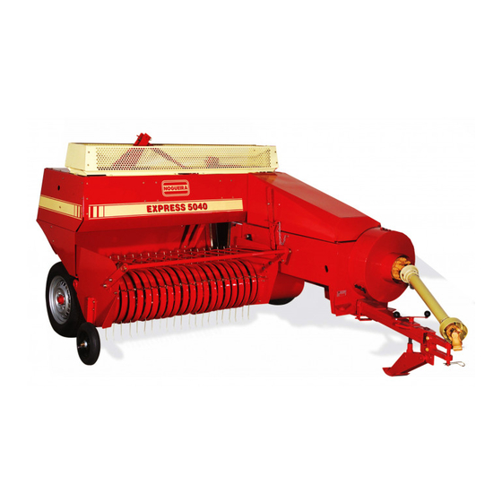
- Página 3 Mr. Owner Congratulations on your purchase of the Baler EXPRESS-5040, a product of the highest quality, specially developed to meet your needs. This manual contains operating, maintenance and safety instructions, which, if properly observed, will guarantee the proper functioning and durability of your Baler.
-
Página 4: Tabla De Contenido
ÍNDICE Safety adhesive labels ................. 11 Safety adhesive labels ................. 12 Presentation ..................13 Functioning ..................13 Truck transporting ................14 Getting to know the baler ..............15 Getting to know the baler ..............16 Getting to know the baler ..............17 The material coming with the baler ............ - Página 5 SAFETY CAUTION! The machine operator must be familiar with the operating procedures, maintenance and safety ƒ Never attempt to pass wires information in this manual. Here are good safety practices, which must be respected during the through the needles when machine use.
- Página 6 ƒ The Instructions Manual must be kept in ƒ When you uncouple the an accessible place to all operators and machine from the tractor, choose a flat surface, in maintenance staff. order to ease the procedure ƒ Adaptations or use of non-original parts and the follow coupling.
- Página 7 OPERATION SAFETY transportation. Whenever it is necessary to climb on the machine to perform any ƒ In order to operate this machine, as well adjustments or repair, turn as performing each maintenance task or off the tractor PTO and wait repair, you must follow all the indicated until all the components are instructions in this manual.
- Página 8 safely, by just one operator, competent, of MAINTENANCE SAFETY legal age, sitting on the driving position of the tractor. ƒ Maintenance activities, ƒ Keep all the shields and protections in inspection and repairs must their proper places and do not operate only be performed by a the machine without them.
- Página 9 ƒ Make use of appropriate protection PERSONAL SAFETY on hands and eyes when you check if ƒ Personal safety as well as there are any high-pressure leaks in the other people’s is one of hydraulic system. Use a piece of wood our major concerns in the or a card instead of using your hands design and development...
- Página 10 ƒ Always keep your hands at a safe distance rough terrain. In order to from moving parts. tow a load when its weight is heavier than the tractor’s, ƒ Never attempt to clean or clear any do not exceed the maximum machine parts when it is turned-on.
-
Página 11: Safety Adhesive Labels
SAFETY ADHESIVE LABELS Turn off the tractor and remove Read the instruction manual befo- the key from the ignition before re turning on the machine. performing any maintenance, adjustment, lubrication, cleaning jobs etc., on the machine. Never place your hands of the tre- Never place your hands of the admill with the machine running. - Página 12 SAFETY ADHESIVE LABELS Never comes close to the collector with the machine running. Do not utilize the driveshaft without the safety shielding. Keep away while it is operating. Contact with the moving driveshaft can cause a serious accident. When operating the harvester, This displays the number of turns w e a r p e r s o n a l p r o t e c t i v e per minute and the direction of the...
-
Página 13: Presentation
PRESENTATION The Baler was planned to operate when being towed by a farm tractor, activated through its power socket. It collects, presses into rectangular bales and ties automatically, using plastic or natural cord (sisal), forage plants used in producting hay, such as: coast-cross, alfalfa, oats, rhodes, rye-grass, clover etc., native grasses and stalks of crops such as: wheat, soybean, rice etc. -
Página 14: Truck Transporting
TRUCK TRANSPORTING Whenever it is necessary to transport the machine over long distances, or if there is a need for the use of public roads, transport must be carried out on a truck or cart. IMPORTANT! The machine must be completely inside the bodywork. It is essential that the header is fixed on the bodywork floorboard, as well as adding wooden shims, which must be fixed on the floorboard. -
Página 15: Getting To Know The Baler
GETTING TO KNOW THE BALER fig. 1 fig. 2 fig. 3 Instructions Manual... - Página 16 GETTING TO KNOW THE BALER fig. 4 fig. 5 fig. 5a Instructions Manual...
-
Página 17: Getting To Know The Baler
GETTING TO KNOW THE BALER fig. 5d fig. 5c fig. 5b THE MATERIAL COMING WITH THE BALER The Baler leaves the factory equipped with two cord rolls. Inside the rear com- partment there is a plastic package containing: - Safety bolt of the needles: 4 parts - Safety belt of the handwheel: 4 parts - Safety bolt of the collector: 4 parts - Operator’s manual: 01 unit... - Página 18 SECTION A CONNECTION Instructions Manual...
-
Página 19: Tractor Required
TRACTOR REQUIRED For a safe and efficient operation, a tractor must be used with power from 35 hp onwards in the power socket, at 540 rpm. ATTENTION This equipment was planned to operate with 540 rpm in the power socket. It must not be used on tractors with a rotation differing from the one indicated. -
Página 20: Work Position
WORK POSITION The Baler leaves the factory with the head in the transport position. Before starting the baling it is necessary to place it the work position, following the instructions below. fig. 10 fig. 11 fig. 12 Position 1: For transport. Position 2: Indicated for places where it is necessary to maneuver the machine constantly (small areas). -
Página 21: Cardan
CARDAN Connect the cardan to the drive shaft of the machine and to the power socket of the tractor, so that the hard part (male) is in the machine and the tubular part (female) is on the tractor. CARDAN TRACTION CUTTING THE CARDAN: fig. - Página 22 SECTION B PREPARATION AND OPERATION Instructions Manual...
-
Página 23: Zeroing The Bale Counter
The Baler leaves the factory duly tested, lubricated and regulated. However, there are some adjustments which need to be made in the work place, according to the operation conditions. In order to obtain the best performance out of your Baler, follow the instructions described in this section correctly. ZEROING THE BALE COUNTER The counter indicates the quantity of bales produced. -
Página 24: Regulating The Compaction Of The Bale
REGULATING THE COMPACTION OF THE BALE The density and, consequently, the weight of the bale, are determined by the tension applied in the compaction crank handles. Owing to the influence of different factors, such as type, density and humidity of the product to be baled, dimensions of the ridges etc., making it very difficult to establish a standard regulation of the compaction. - Página 25 NOTE: The largest part of the problems occurring in the mooring of the bales is related to excessive compaction. Start the baling with a gap of approximately 2 cm in the two crank handles, as shown in figure below. Let the first two bales exit and see the compaction, adjusting it as required. fig.
-
Página 26: Height Of The Collector
HEIGHT OF THE COLLECTOR The Baler leaves the factory with the collector adjusted to the transport position. Before starting the baling it must be placed in the work position. springs fig. 24 On land suitable for baling, the distance between the tips of the collecting springs and the soil must be approximately 3 cm (see fig.24). - Página 27 REGULATING THE HEIGHT OF THE WHEEL OF THE COLLECTOR: The function of this wheel is to allow the collector to accompany the undulations when the baler works on uneven land. After regulating the collection height, seen on the previous page, the height of the wheel must be regulated, pro- ceeding in the following manner: - Remove the four nuts and washers B.
-
Página 28: Placing The Cord Rolls
PLACING THE CORD ROLLS Your Baler is prepared to operate with cords or natural fiber (sisal) or plastic cords, as defined by the user. Cords with a bad quantity will certainly cause problems during the tying of the bale. NOTE: Cord of natural fiber (sisal) has a resistance in the knot of 57 through 73 kg whereas that of the plastic cord is of 59 through 127 kg. - Página 29 HOW TO JOIN THE ENDS OF THE CORDS (SISAL): This is a very important operation, as a badly tied knot may damage the ne- edles. The procedure is simple, as we described below: fig. 32 fig. 34 Separate the ends of the cords. Link the ends together.
- Página 30 HOW TO JOIN THE ENDS OF THE CORDS (PLASTIC CORD): fig. 37 fig. 38 Link the ends together. Make a simple knot. fig. 40 fig. 39 Trim the ends with a pair of scissors. Tighten the knot well. Instructions Manual...
- Página 31 PLACING THE CORDS Disconnect the power socket and the tractor engine. See that the needles are lowered. If required, manually turn the hand wheel, in the direction of the arrow on it, until the needles are totally lowered. Lock the knotmaker. Take the end of the cord, from inside roll A, and put it on the points 1, 2, 3, 4, 5, 6, 7, 8 (tip of the needle) and tie it to the needle support 9.
-
Página 32: Wheels
WHEELS Verify the pressure of the tires. After between the first 4 and 8 hours of work, retighten all the nuts of the wheels. Frequently verify the tightening during the first 100 hours of work. fig.45 35 lbs/pol (2,4 Kg/cm 40 lbs/pol (2,8 Kg/cm RAMMER... -
Página 33: Baling
BALING IDEAL POINT: The plant attains the haymaking point when it has a humidity of below 20% - ideally between 15 and 18%. At this point, the material must be collected from the field as quickly as possible, avoiding loss of quantity of the hay, caused by excessive dryness or unforeseen rain. -
Página 34: Operation
OPERATION Having observed the procedures described on the previous pages, the baler is ready to start operating. Before turning it on: - Carefully verify that there are no objects or tools in or on the machine. - Check that there are no people or animals very near. A safe distance must always be maintained from the machine. -
Página 35: General Tips
Never try to disconnect the baler when it is baling. Wait until it is completely empty before disconnecting it. Only leave the tractor after having disconnected the power socker and the engine, as well as having activated the parling brake and removed the key from the ignition. CARE! Park the baler on level ground and block the wheels to stop it moving. -
Página 36: Maintenance And Lubrication
SECTION C MAINTENANCE AND LUBRICATION Instructions Manual... -
Página 37: Periodic Maintenance Table
PERIODIC MAINTENANCE TABLE Instructions Manual... -
Página 38: Maintenance
MAINTENANCE The periodic maintenance performed adequately, is the most effective way to ensure maximum efficiency and durability for its baler. The use of parts or non-original factory accessories may Important! cause accidents, damage the equipment and affect its operation, as well as involve the loss of warranty provided. Turn off the PTO and remove the ignition key of the tractor, before making adjustments, settings, lubrication or maintenance on the machine. -
Página 39: Sharpening And Regulating The Blades
SHARPENING AND REGULATING THE BLADES In order to provide a clean and efficient cut, the blades must be maintained sharpened and regulated. It is advisable to verify them every 15,000 bales, approximately. When required, execute the sharpening, as described on the following page. -
Página 40: Safety Systems
SAFETY SYSTEMS The Baler has three safety devices planned to protect the mechanisms in case there is an overload or foreign bodies enter into the machine. The good func- tioning of these devices is indispensable to ensure the maximum protection for the equipment. - Página 41 IMPORTANT! Only use the genuine safety bolts. If it breakes, check that the ridges are not very dense or above the recommended size, overloading the machine. If so, reduce the speed of the tractor. Excessive com- paction of the bales can also cause the safety bolt to break.
- Página 42 3- Remove the cotter pin and disassemble the pin B. CARE! If the safety bolt is broken, the arm C is loose, and upon removing the pin B it goes down. 4- Remove the broken end of the safety bolt, which may be in the point of the arm C.
-
Página 43: Regulating The Pressing Piston
IMPORTANT! In order to ensure the perfect and safe functioning of the device, only use a genuine safety bolt. REGULATING THE PRESSING PISTON The compacting piston moves in the pressing chamber guided by side rules and rollers. The adjustment is executed by means of these rules and rollers, eliminating possible gaps. -
Página 44: Synchronism Of The Feeding Arms
SYNCHRONISM OF THE FEEDING ARMS The arms’ function is to place the material picked inside the pressing chamber. In order for the chamber feeding to be uniform and to prevent the collision of the two arms, it is necessary a perfect synchronism of movement between them. The figure at the below shows the positioning of the crank handles (parts in black) when the arms are correctly synchronized. - Página 45 SYNCHRONIZING THE ARMS: With the power socket and the tractor engine disconnected: 1- Open the covers A and B. 2- Put the cord rolls in the lower compartment. 3- Disassemble the separating support of the rolls C. fig. 64 fig. 65 1- Remove the screw D.
- Página 46 5- Using a stop pin, move the hexagonal shaft G until removing it from the pinion H, (see fig.69). fig. 68 fig. 69 When the hexagonal shaft exits the pinion F, the arms become loose and, owing to their weight, do down abruptly.
-
Página 47: Feeding Arm/ Piston Synchronism
FEEDING ARM/ PISTON SYNCHRONISM Whenever the piston moves and releases the opening into the pressing chamber, the feeding arm takes material, through the opening, inside the chamber. This operation is very fast, occurring 100 times a minute, and requires perfect synchronism between the arm and the piston, so that they do not collide. - Página 48 SYNCHRONIZING ARM AND PISTON: NOTE: Remember that before adjusting the arm with the piston, adjustment should be made between the two arms, as described in the item ‘ADJUSTING THE POWER ARMS’ in this manual. With the power socket and the tractor engine disconnected: 1- Open the cowling A and the rear cover B.
- Página 49 7- Turn the handwheel manually until the measure M (fig.77) is equal 580 to 600 mm. 8- Assemble the hexagonal shaft again in the pinion G and replace the screw E. 9- Replace the screw D. 10- Replace the separator C. 11- Close the covers and the cowling.
-
Página 50: Regulating The Needles With The Knotters
REGULATING THE NEEDLES WITH THE KNOTTERS In order to assure the efficiency in tying the bales and prevent that the needles and the support get damaged, it is important to keep the needles adjusted, according to instructions as follows: 1 – With the tractor engine off and the key removed from the ignition: 2 - Manually turn the star wheel F (as the arrow indicates below), until the arm G moves forward, releasing the mechanism from the knotter. - Página 51 There must be a slack from 2-4mm between the lower end from the needle and the retainer disk (mea- sure A) In case the slack is outside the pat- terns indicated above, proceed as follows: fig. 81 Measure A = 2 to 4 mm IMPORTANT! The needle must be centered with RETAINER DISC...
- Página 52 REGULATING THE MOVEMENT OF THE NEEDLES (measure B). After regulating the needles with the retainer disks, procedure described on the previous page, regulate the movement of the needles, described as follows: 1 – Open the side cover L (picture 84). fig.
- Página 53 NEEDLE With the needles placed in the highest DISC point, the measure B must be from 135 to 140mm (picture 88). fig. 88 Measure B = Distance from the needle tip from the disk = 135 to 140mm. 3 – remove the side shield V. 4 –...
- Página 54 ATTENTION! If the measure B is higher than recommended (140mm), the needles support will hit the pressing chamber when the needles go up to the knotter, damaging the support. Keep measure B between 135 to 140mm. NEEDLE DISC fig. 91 Measure B = Distance from the needle tip from the disk = 135 to 140mm.
-
Página 55: Regulating The Handles Of The Thread
REGULATING THE HANDLES OF THE THREAD Before adjusting the handles is fundamental to adjust the needles as described in the preceding pages. This sequence is important as the correct placement of needles will prevent the same eventually hit the grips. ADJUSTING OF THE DISTANCE OF THE HANDLES WITH THE NEEDLES 1- To facilitate the adjustment, remove the screw A and lift the frame knotmaker (fig.94). - Página 56 ADJUSTING THE POSITION OF HANDLES After the settings of needles and handles displayed on the previous page, down the needles, turning manually the steering wheel. With fully downloaded ne- edles, the measure M must be equal to 5 mm (fig.96). In case of divergence, proceed as follows: IMPORTANT! There are several factors that interfere when you tie a knot, and, in some cases,...
-
Página 57: Synchronizing The Needles With The Piston
SYNCHRONIZING THE NEEDLES WITH THE PISTON When the bale is ready to be tied, a mechanism starts the needles, which cross the pressing chamber, going inside the moving piston channel, taking the tying cords to the knotmaker. In order for this movement to occur without there being a collision, the piston and the needles must work in perfect synchronism. - Página 58 2. Turn the handwheel manually until the tips of the needles are 5 to 10 milli- meters above the bottom of the channel, measure A of fig.99. fig. 110 fig. 99 IMPORTANT! So that the adjustment is correct and that the needles are not damaged, it is necessary to pay attention to the following detail: Upon turning the handwheel, the piston must move in the direction of compacting the bale, i.e.
- Página 59 3- Remove the setscrew of the pinion D. 4- Move the pinion D to the left side (in the direction of the arrow of fig.102) until the pinion is uncoupled from the gear E. 5- Turn the handwheel manually, in a counterclockwise direction, until the piston exceeds the tips of the needles by 20 to 25 mm, measure B of fig.101.
-
Página 60: Knotter Trigger Regulation
KNOTTER TRIGGER REGULATION The trigger leaves the factory properly regulated, and it does not need any ad- justments. There should be a slack of 4 to 5mm between the trigger and the roller. In case it is not adjusted, proceed as follows: 1 –... -
Página 61: Correcting The Format Of The Bale
CORRECTING THE FORMAT OF THE BALE The good formed bale depends on the uniformity in feeding the machine. Defor- med bales are produced when the pressing chamber is fed unevenly (a greater quantity of material on one side or the other). If the position of pin A is changed, the penetration of the fork inside the pressing channel is altered, allowing the amount of material to be increased or decreased on one side or other of the bale. - Página 62 Another way of improving the uniformity of the bale is to reposition the teeth of the collecting fork, as per the instructions below: fig. 124 fig. 125 Descending the teeth increases Raising the teeth increases the the product volume on the outer product volume on the inner side of the bale.
-
Página 63: Adjustments Of The Knotmakers
ADJUSTMENTS OF THE KNOTMAKERS Never attempt to make any adjustment in the knotmaker with machine on. Always turn off CAUTION the PTO and the tractor engine before starting a regulation. KNOTMAKER FOOT (A) It consists of a shaft ending in a hook shape. Inside this a movable member is mounted called “tongue”... - Página 64 TONGUE PRESSURE IN THE KNOTMAKER FOOT The presser foot pressure on the roller tongue is exercised by a flat spring, stuck in the foot itself (fig.134). NOTA: The tongue must open upon a pressure of 5 to 10 kg at one end. The spring should not be blocked under any circumstances.
- Página 65 1- Turn off the PTO and the tractor engine and remove the key from the contact. 2- Remove the screw and lift the knotmaker (fig.136 and 137). CAUTION! When lifting the knotmaker, the knife holder arm will move may cause injury in your hands.
- Página 66 The arm knife holder has on its bottoom a small slot (shown in fig.141), which should pass close to the knotmaker foot to remove the loop. If there is a gap in this place, the loop will not be removed from the stand and the cord will be crushed or damaged.
-
Página 67: Adjustment Of The Retaining Disk
ADJUSTMENT OF THE RETAINING DISK The retaining disk has four rabbets where the cord goes. These rabbets must be correctly positioned. If the cord does not touch the rabbet, it will not be caught between the retaining clamp and disk and will not be able to be cut by the blade. -
Página 68: Adjustment Of The Retaining Clamp
ADJUSTMENT OF THE RETAINING CLAMP When tying the bale the cord is caught between the retaining clamp and disk. During this process, the retaining clamp is pressed by two springs against the disk, fastening the cord. The pressure that these springs exert on the disk is very important. -
Página 69: Regulating The Needles Brake
KNOTMAKER BLADE The blades of the knotmakers are responsible for cutting the cords after tying the bale. If they are not sharp, they will not cut evenly. They must be sharpened or replaced when worn. BLADE fig.149 REGULATING THE NEEDLES BRAKE The height L of the brake spring must remain equal to the height of the reference plate B. -
Página 70: Regulating The Brake Of The Knotmaker
REGULATING THE BRAKE OF THE KNOTMAKER The compression of the springs of fig.152, determine the appropriate retention of the threads for tying the baldes. Their adjustments is made through the two nuts B. The ideal compression will depend on field conditions such as type of product, moisture content etc., and the blae compression level. -
Página 71: Revision
REVISION It is advisable to execute a general revision of the Baler every year, preferably at the end of each season, identifying and replacing worn or damaged parts. Whenever you need replacement parts, go to your authorized reseller, with the manufacturing serial number and model of your machine. -
Página 72: Lubrication
LUBRICATION The Baler was conceived to require a minimum of lubrication. Regular lubrication is the best guarantee of substantially increasing the useful life of the machine. IMPORTANT! ÓLEOS RECOMENDADOS The lack of oil causes overheating PETROBRAS LUBRAX GEAR 150 and damage to the components of CASTROL HYSPIN AWS 150 the box. - Página 73 LUBRICATION OF THE LOWER TRANSMISSION BOX Recommended lubricant: 150 CLP or similar. First change: 50 hours of work. Quantity of oil: 1 liter. Next changes: every 150 hours of work. NOTE: Verify the level and fill it up if required, by means of the screw R, every 50 hours of work.
-
Página 74: Lubrication Points With Grease
LUBRICATION POINTS WITH GREASE Lubricate with grease, at the intervals indicated, all the points identified below. We recommend the use of lubricating grease of good quality, with a base of lithium soap, classification NLGI degree 2. After the lubrication remove the excess of grease from the oilers. ÍTEM MAXIMUM INTERVAL Crosspieces of the cardan... - Página 75 ÍTEM MAXIMUM INTERVAL Knotmaker (2 oilers) 10 hours Knotmaker (2 oilers) 10 hours Arm (1 oiler) 10 hours Pinion (2 oilers) 10 hours Lever (1 oiler) 10 hours Knotmaker bearing (2 oilers) 10 hours Gear (1 oiler) 10 hours Knotmaker rod (1 oiler) 10 hours Knotmaker (4 oilers) 10 hours...
-
Página 76: Accessories
ACCESSORIES The Bale hoist is an accessory, supplied upon request, used to unload the bales into a cart connected to the baler. To use it, the bales should be: - As uniform as possible. - Tied with cords of a good quality. - Sufficiently dry to slide easily. - Página 77 SECTION D PRACTICAL GUIDE Instructions Manual...
-
Página 78: Practical Guide
PRACTICAL GUIDE Below we present the most common symptoms of operation failures, their probable causes and the precautionary measures required. If you have any queries, see your reseller or contact the technical assistance department of. SYMPTOM CAUSE PROCEDURE 1- Disconnect the power The cardan is knocking 1- Closed curves socket when doing clo-... - Página 79 SYMPTOM CAUSE PROCEDURE 1- Ball with suitable Product is accumulating humidity. between the collector and 1- Product very wet. the table. 2- Reduce the work speedand collect less material. 2- Press is overloaded. 3- Straighten the teeth 3- Teeth of the rammer are twisted.
- Página 80 SYMPTOM CAUSE PROCEDURE Uneven bale (more 1- Use upper hole. 1- Collecting arm material outside, on side desregulated. opposite blade). 1- Collecting arm Uneven bale (more 1- Use upper hole. desregulated. material inside, on blade side). 1- Regulate compac- Bale twisted. tion with the two crank 1- Unequal compaction.
- Página 81 SYMPTOM CAUSE PROCEDURE Excessive breaking of 1- Use genuine bolt. 1- Bolt inappropriate. safety bolt of handwheel 2- Safety bolt loose. 2- Tighten safety bolt appropriately. 3- Baling with excessive 3- Adapt the compac- compaction. tion. 4- Sharpen blades and 4- Blades blunt or with adjust gap.
- Página 82 SYMPTOM CAUSE PROCEDURE 1- Reduce speed of the Noise in the upper arms. 1- Springs of the arms tractor to bale conti- Oil level low. are compressed indi- nuously without cating compressing the sprin- overload. 1- Change the retainer 1- Retainer leaking. and fill up the oil.
- Página 83 SYMPTOM CAUSE PROCEDURE 1- Sharpen or replace 1- The blade is blunt. The knot is badly done, the blade. one of the ends of the cord being bigger than the other or there is a 2- Increase the tension 2- Tension very low in the loop at the in the spring.
- Página 84 SYMPTOM CAUSE PROCEDURE 1- Needle in the incorrect Knot only in the cord 1- Adjust the position of position. the needle in the the upper side. respective support. 2- Cord catcher 2- Adjust the position of desregulated. the cord related to the bale channel.
- Página 85 SYMPTOM CAUSE PROCEDURE 1- Reduce the tension of 1- A lot of tension in the The knots are caught on the tongue of the knotmaker support. the support of the knotmaker support. knotmaker. 2- Adjust blade holder 2- A large gap between arm.
-
Página 86: Technical Features
SECTION E TECHNICAL FEATURES Instructions Manual... -
Página 87: Technical Specifications
TECHNICAL SPECIFICATIONS Minimum power for activation (in the power socket) ......35 hp Rotation (in the power socket) ............ 540 rpm Net weight (without hoist) ............1.460 kg Tires: Left (side of the pressing chamber) ........10.5/65 - 16 Right (collecting side) ............... 5.60 - 15 Pressure in the tires: Left (channel side of pressing) ...... -
Página 88: Warranty Certificate
09 (nine) last months - additional warranty granted by Nogueira Máquinas Agrícolas. 2- This warranty is based on Nogueira's commitment to repair or provide free of charge in its factory any parts that in their sole discretion have manufacturing defects. The warranty covers only defects in material and / or workmanship, and labor, freight and other expenses are not covered by this certificate. - Página 89 Sr. Propietario Felicitaciones por la compra de la Enfardadeira EXPRESS-5040 NOGUEIRA, un producto de la más alta calidad, especialmente desarrollado para atender sus necesidades. Este manual contiene instrucciones de operación, mantenimiento y seguridad, que si debidamente observadas, serán la garantía de buen funcionamiento y durabilidad de su Cabezal.
- Página 90 Contents ÍNDICE Adhesivos de seguridad ................. 9 Adhesivos de seguridad ..............10 Presentación ..................11 Funcionamiento .................. 11 Conociendo la enfardadora ..............13 Conociendo la enfardadora ..............14 Conociendo la enfardadora ..............15 Qué acompaña la enfardadora .............. 15 Tractor requerido ................17 Posición de trabajo ................
-
Página 91: Seguridad
SEGURIDAD CUIDADO! El operador de la máquina debe familiarizarse con los procedimientos de operación, ƒ Nunca intente pasar los mantenimiento y la información de SEGURIDAD contenida en este manual. En él se indican cables por las agujas con las buenas prácticas de seguridad que deben la máquina conectada. -
Página 92: Seguridad De Perparación
ƒ Leer el manual de instrucciones antes de máquina, observando si arrancar la máquina. Manténgase atento no hay tornillos sueltos, piezas gastadas, roturas, y respete todas las recomendaciones de uso y seguridad durante la operación. fugas, corrientes sueltas. REPASAR LA INFORMACIÓN PARA LOS Hacer las reparaciones DEMÁS USUARIOS. - Página 93 SEGURIDAD EN LA OPERACIÓN a distancia segura. Tenga especial cuidado con los niños. ƒ Para la operación de esta máquina, así como para toda tarea de mantenimiento o ƒ Q u e d a p r o h i b i d a l a reparación, deben seguir las instrucciones permanencia de personas indicadas en el presente manual.
- Página 94 ƒ Si observa cualquier anormalidad en SEGURIDAD EN EL el funcionamiento, vibraciones, ruidos MANTENIMIENTO diferentes, etc., apagar la máquina inmediatamente, comprobar y eliminar ƒ L a s a c t i v i d a d e s la causa antes de volver a encenderla. mantenimiento, inspección ƒ...
- Página 95 ƒ Asegúrese de que todos los componentes SEGURIDAD PERSONAL del sistema se mantienen en buen ƒ La seguridad del operador y estado. demás personas es una de las ƒ Sustituir inmediatamente mangueras principales preocupaciones aplastadas y dañadas. e n e l c o n c e p c i ó n y e l desarrollo de una máquina.
- Página 96 ƒ Mantener las manos siempre alejadas de en lugares accidentados. Al las piezas en movimiento. remolcar una carga con peso mayor que el del tractor, no ƒ Nunca intente limpiar o separar cualquier sobrepasar 16 Km / hora. parte de la máquina mientras esté encendida.
-
Página 97: Adhesivos De Seguridad
ADHESIVOS DE SEGURIDAD Apague el tractor y retire la llave del Lea el Manual de instrucciones antes arranque antes de realizar servicios de encender la cosechador a . demantenimiento, regulación, Manteniéndose atento y respetando lubricación, limpieza etc., en todas las recomendaciones de uso y la cosechadora. - Página 98 ADHESIVOS DE SEGURIDAD Mantenga distancia segura del recolector durante la operación. Existe riesgo de lesiones causadas por componentes No utilice el cardán sin la protección en movimiento. de seguridad. Mantenga distancia durante el funcionamiento. El contacto con el ardán en movimiento podrá...
-
Página 99: Presentación
PRESENTACIÓN La Enfardadora recoge, prensa en fardos rectangulares y ata automáticamente, utilizando hilo plástico o natural (henequén), plantas forrajeras utilizadas en la producción de heno, tales como: coast-cross, tifton, alfalfa, avena, rhones, azevén, trébol, etc., pastos nativos y pajas de culturas como: trigo, soya, arroz y otros. -
Página 100: Transporte Sobre Camión
TRANSPORTE SOBRE CAMIÓN Siempre que fuere necesario transportar la máquina en distancias mayores, o surja la necesidad de la utilización de vías públicas, el transporte debe ser hecho con camión o acoplado. ¡IMPORTANTE! La máquina debe estar completamente e n e l i n t e r i o r d e l a c a r r o c e r í a . Es fundamental que el encabezado sea fijado en el piso de la carrocería y las ruedas apoyadas con cuñas de madera, que deben ser fijadas... -
Página 101: Conociendo La Enfardadora
CONOCIENDO LA ENFARDADORA fig. 1 fig. 2 fig. 3 Dispositivo de reglaje de la altura del recogedor Volante Cabezal de enganche al tractor Cardán (toma de fuerza) Gato Cable de destrabamiento del cabezal Resortes recogedores Rueda copiadora del recogedor Rueda (lado derecho) 10 Recogedor 11 Mesa alimentadora 12 Calzador... - Página 102 CONOCIENDO LA ENFARDADORA fig. 4 fig. 5 fig. 5a 17 Canal de salida de los fardos 18 Cámara de prensado 19 Compartimiento de los hilos 20 Anudadores 21 Manivelas de compactación del fardo 22 Regulador de longitud del fardo 23 Soporte de las agujas 24 Traba del anudador 25 Agujas Manual de Instrucciones...
-
Página 103: Conociendo La Enfardadora
CONOCIENDO LA ENFARDADORA fig. 5d fig. 5c fig. 5b 26 Pie del anudador 27 Brazo portacuchilla 28 Cuchilla 29 Sinfín 30 Resorte 31 Disco retén 32 Tensor de la lengueta 33 Agarrador del bramante QUÉ ACOMPAÑA LA ENFARDADORA La Enfardadora sale de la fábrica con dos rodillos de hilos. Se encuentra adentro del compartimiento trasero un embalaje plástico conteniendo: - Tornillo fusible de las agujas: 4 piezas. - Página 104 SECCIÓN A ACOPLAMIENTO Manual de Instrucciones...
-
Página 105: Tractor Requerido
TRACTOR REQUERIDO Para una operación segura y eficiente, debe ser utilizado un tractor con potencia a partir de 35 cv en la toma de fuerza, a 540 rpm. ¡ATENCIÓN! Este equipo fue proyectado para operar con 540 rpm en la toma de fuerza. -
Página 106: Posición De Trabajo
POSICIÓN DE TRABAJO La Enfardadora sale de fábrica con el cabezal en la posición de transporte, antes de iniciar el enfardamiento es necesario ponerlo en la posición de trabajo, según lo descrito en las instrucciones a continuación. fig. 10 fig. 11 fig. -
Página 107: Cardán
CARDÁN Como la distancia entre la toma de fuerza y el eje de la máquina puede variar en los diferentes modelos de tractores existentes en el mercado, eventualmente el cardán podrá quedarse muy largo. En ese caso, hay que regular la posición de la barra de tracción del tractor. -
Página 108: Preparación Y Operación
SECCIÓN B PREPARACIÓN Y OPERACIÓN Manual de Instrucciones... -
Página 109: Contador De Fardos
La Enfardadora sale de la fábrica tras haber sido probada, lubricada y regulada. Sin embargo, hay algunos ajustes que necesitan ser hechos en el sitio de trabajo, de acuerdo con las condiciones de operación. Observe las instrucciones a seguir: CONTADOR DE FARDOS El contador indica la cantidad de fardos producidos. -
Página 110: Compactación De Los Fardos
COMPACTACIÓN DE LOS FARDOS La densidad y, consecuentemente, el peso de los fardos son determinados por la compresión aplicada en las manivelas de compactación. Debido a la influencia de diversos factores, tales como: el tipo, la densidad y la humedad del producto a ser enfardado, las dimensiones de los surcos etc., se hace muy dificil establecer un reglaje patrón de compactación. - Página 111 Se recomienda proceder de forma práctica, iniciando el enfardamiento con poca compactación, dejar que salga el primer fardo de la máquina, examinar la compactación y ajustarla conforme sea necesario. El experimento mostrará al operador el correcto reglaje para la obtención de fardos con las características deseadas.
-
Página 112: Regulando La Altura De Recogimiento
REGULANDO LA ALTURA DE RECOGIMIENTO La Enfardadora sale de la fábrica con el recogedor ajustado en la posición de transporte. Antes que empiece el enfardamiento hay que ponerlo en la posición de trabajo. resortes fig. 24 En terrenos adecuados para el enfardamiento, la distancia entre las puntas de los resortes recogedores y el suelo debe ser de 3 cm aproximadamente (vea la fig.27). -
Página 113: Regulando La Altura De La Rueda Del Recogedor
REGULANDO LA ALTURA DE LA RUEDA DEL RECOGEDOR: La función de esta rueda es permitir que el recogedor acompañe las ondula- ciones cuando la enfardadora trabaje en terrenos irregulares. Después del reglaje de la altura de recogimiento, visto en la página anterior, se debe regular la altura de la rueda, procedimiento de la siguiente manera: Remueva las cuatro tuercas y las arandelas C. -
Página 114: Colocando Los Rodillos De Los Hilos
COLOCANDO LOS RODILLOS DE LOS HILOS Su Enfardadora está preparada para operar con hilos de fibra natural (henequén) o hilos plásticos, siendo que la elección queda a criterio del usuario. Es importante la utilización de un hilo de buena calidad y con el diámetro uniforme. Hilos de mala calidad ciertamente causarán problemas durante la amarradura del fardo. -
Página 115: Como Unir Las Puntas De Los Hilos (Henequén)
COMO UNIR LAS PUNTAS DE LOS HILOS (HENEQUÉN): Esta es una operación muy importante, pues un nudo mal hecho podrá dam- nificar las agujas. El procedimiento es sencillo, conforme describimos a seguir: fig. 32 fig. 34 Deshilar las puntas de los hilos. Entrelazar las puntas. -
Página 116: Como Unir Las Pontas De Los Hilos (Hilo Plástico)
COMO UNIR LAS PONTAS DE LOS HILOS (HILO PLÁSTICO): fig. 37 fig. 38 Entrelazar las puntas. Hacer un nudo sencillo. fig. 40 fig. 39 Cortar las puntas con una tijera. Apretar bien el nudo. Manual de Instrucciones... -
Página 117: Colocación De Los Hilos
COLOCACIÓN DE LOS HILOS Desconecte la toma de fuerza y el motor del tractor. Observe si las agujas están bajadas. En caso necesario, gire manualmente el volante en el sentido de la flecha existente en el mismo, hasta que las agujas bajen por completo. -
Página 118: Neumáticos
NEUMÁTICOS Verifique la presión de los neumáticos. Entre las primeras 4 y 8 horas de trabajo, reapriete todas las tuercas de las rue- das. A menudo, verifique el aprieto durante las primeras 100 horas de trabajo. fig.45 35 lbs/pol (2,4 Kg/cm 40 lbs/pol (2,8 Kg/cm CALZADOR... -
Página 119: Enfardando
ENFARDANDO ESTADO IDEAL: La planta llega al estado de heno cuando presenta humedad inferior a los 20% lo ideal está entre el 15% y el 18%. En este estado, el material debe ser recogido del campo lo más pronto posible, evitando la pérdida de la calidad del heno, causada por el secado excesivo o por las lluvias imprevistas. -
Página 120: Operación
OPERACIÓN Observados los procedimientos descritos en las páginas anteriores, la enfardadora está preparada para entrar en operación. Antes de prenderla: - Verifique con atención si no hay objetos o herramientas dentro o sobre la máquina. - Observe si no hay personas o animales muy próximos. Siempre hay que man- tener una distancia segura de la máquina. -
Página 121: Pistas Generales
No desconecte la enfardadora mientras esté enfardando. Espere hasta que esté completamente vacía para desco- nectarla. Solamente abandone el tractor después de desconectar la ¡CUIDADO! toma de fuerza, el motor, accionar el freno de mano y quitar la llave de contacto. Estacione la enfardadora en un sitio plano y bloquee las ruedas. -
Página 122: Mantenimiento Y Lubricación
SECCIÓN C MANTENIMIENTO Y LUBRICACIÓN Manual de Instrucciones... -
Página 123: Tabla De Mantenimiento Periódico
TABLA DE MANTENIMIENTO PERIÓDICO ITEM INTERVALO OBS. DE SERVICIO- Después de Tornillos y tuercas de fijación las 25 hrs. iniciales Cajas de transmisión Después de las 50 hrs. Tubo del cardán Cada 10 horas Biela del Pistón Rueda (lado salida del fardo) Rueda del recogedor Accionador de las agujas Crucetas del cardán... -
Página 124: Mantenimiento
MANTENIMIENTO Para proporcionar mayor clareza y facilitar la identificación de partes internas de la máquina, algunas fotos usadas en este manual pueden mostrar protecciones abiertas o quitadas. Su revendedor dispone de una completa línea de piezas Importante! de repuesto. Solamente las piezas originales son hechas con materias primas seleccionadas, según rígido proceso de fabricación y cuidadosa inspección. -
Página 125: Afilando Y Regulando Las Cuchillas
AFILANDO Y REGULANDO LAS CUCHILLAS Para proporcionar un corte limpio y eficiente, las cuchillas deben estar afiladas y reguladas. Se recomienda una verificación cada 15.000 fardos aproximadamente. Cuando necesario, proceder el afilamiento, conforme descrito abajo. Las cuchillas poseen un corte agudo. Cuidado para no herirse al manosearla. -
Página 126: Sistemas De Seguridad
SISTEMAS DE SEGURIDAD La Enfardadora posee tres dispositivos de seguridad desarrollados para proteger los mecanismos en el caso de sobrecarga o entrada de cuerpos extraños adentro de la máquina. El buen funcionamiento de estos dispositivos es indispensable para garantizar la máxima protección al equipo. DISPOSITIVO DE SEGURIDAD DELVOLANTE: El tornillo de seguridad ubicado en el volante (fig.56), se rompe en caso de sobre- carga o entrada de algún cuerpo extraño durante la alimentación, deteniéndose... -
Página 127: Tornillo De Seguridad De Las Agujas
¡IMPORTANTE! Utilice solamente los fusibles originales. En caso de quiebra, observe si los surcos no están muy densos o arriba del tamaño recomendado, sobrecargan- do la máquina. En este caso, disminuya la velocidad de desplazamiento del tractor. La compactación excesiva de los fardos también puede provocar la quiebra del fusible. -
Página 128: Tornillo De Seguridad Delrecogedor (A)
3- Quite el contrapasador y desmonte el pasador B. CUIDADO! Con el tornillo fusible roto, el brazo C se queda suelto y al quitar el pasador B, el bajará. 4- Quite la punta rota del tornillo fusible, que posiblemente estará en la punta del brazo C. -
Página 129: Regulando El Pistón De Prensado
¡IMPORTANTE! Para garantizar el funcionamiento perfecto y seguro del dispositivo, utilice solamente tornillo fusible original. REGULANDO EL PISTÓN DE PRENSADO El pistón compactador se desplaza adentro de la cámara de prensado guiado por rollos pequeños y reglas laterales. Es a través de uno de estos rollos pequeños y de estas reglas que se hace el reglaje, eliminando eventuales holguras. -
Página 130: Sincronizando Los Brazos Alimentadores
SINCRONIZANDO LOS BRAZOS ALIMENTADORES La función de los brazos es colocar dentro del canal de prensado el material recogido. Para que la alimentación del canal sea uniforme y no ocurra la colisión entre los dos brazos, es necesario un perfecto sincronismo de movimiento entre los mismos. -
Página 131: Procedimiento Para Sincronizar Los Brazos
PROCEDIMIENTO PARA SINCRONIZAR LOS BRAZOS: Con la toma de fuerza y el motor del tractor desconectados: 1- Abra las tapas A y B. 2- Pase los rodillos de hilos para el compartimiento de abajo. 3- Desmonte el soporte separador de los rodillos C. fig. - Página 132 8- Utilizando un pasador batidor, desplace el eje hexagonal G hasta quitarlo del piñón H (observe las figuras 68 y 69). fig. 68 fig. 69 Cuando el eje hexagonal sale del piñón F, los brazos se y, debido al peso, bajan bruscamente. Es importante calzar los brazos antes de empezar el reglaje, a fín de revenir accidentes.
-
Página 133: Sincronizando Brazo Alimentador / Pistón
SINCRONIZANDO BRAZO ALIMENTADOR / PISTÓN Toda vez que el pistón se mueve y libera la boca de entrada de la cámara de prensado, el brazo juntador conduce material, a través de la boca, hacia dentro de la cámara. Esta operación es muy rápida, ocurre 100 veces por minuto, y requiere un perfecto sincronismo entre el brazo y el pistón, para que no ocurra la colisión de ambos. -
Página 134: Procedimiento Para Sincronizar El Brazo Con El Pistón
PROCEDIMIENTO PARA SINCRONIZAR EL BRAZO CON EL PISTÓN NOTA: Recuerde que antes de regular el brazo con el pistón, se debe hacer la regulación entre los dos brazos, como se describe en el ítem ‘REGULACIÓN DE LOS BRAZOS ALIMENTADORES’ en este manual. Con la toma de fuerza y el motor del tractor desconectados: 1- Abra el capó... - Página 135 7- Abra el capó frontal H (fig.77). 8- Gire manualmente el volante hasta biela que la medida M = 580 hasta 600 mm (fig.77). 9- Monte nuevamente el eje hexago- nal en el piñón G y recoloque el tornillo E. 10- Recoloque el tornillo D.
-
Página 136: Regulación De Las Agujas Con Los Anudadores
REGULACIÓN DE LAS AGUJAS CON LOS ANUDADORES Para asegurar la eficiencia en el amarre de los fardos y evitar que las agujas y el soporte se dañen, es importante mantener las agujas reguladas según las siguientes instrucciones: 1.- Con el motor del tractor apagado y la llave retirada del arranque: 2.- Gire manualmente la rueda activadora F (sentido de la flecha de la figura abajo), hasta que el brazo G desplaza hacia delante, liberando el mecanismo del hacedor de nudos. -
Página 137: Regulación De La Holgura De La Aguja Con O Disco Retenedor
Debe haber una holgura de 2 a 4 mm entre el extremo inferior de la aguja y el disco retenedor (medida Si el juego está fuera del rango arriba indicado, proceda como se describe a continuación. fig. 81 medida A = 2 a 4 mm ¡IMPORTANTE! DISCO RETENEDOR La aguja debe estar centralizada con... - Página 138 REGULACIÓN DEL AVANCE DE LAS AGUJAS (medida B) Después de la regulación de las agujas con los discos retenedores, descrita en la página anterior, ajuste el avance de las agujas, como se describe a continuación. 1. Abra la tapa lateral L (fig.84). 2.
- Página 139 AGUJA DISCO Con las agujas colocadas en el punto más alto, la medida B debe ser de 135 a 140 mm (fig 88). fig. 88 medida B = Distancia de la punta de la aguja hasta el disco = 135 a 140 mm. 3.
- Página 140 ¡ATENCIÓN! Si la medida B es mayor de la recomendada (140 mm), el soporte de las agujas se golpeará en el canal de prensado cuando las agujas suben hasta el hacedor de nudos, dañando el soporte. Mantenga la medida B entre 135 y 140 mm. AGUJA DISCO fig.
-
Página 141: Regulando Los Agarradores De Los Hilos
REGULANDO LOS AGARRADORES DE LOS HILOS Antes de regular los agarradores es fundamental ajustar las agujas, conforme lo descrito en las páginas anteriores. Esta secuencia es importante, pues el posicionamiento correcto de las agujas evitará que las mismas, eventualmente, se peguen contra los agarradores. -
Página 142: Ajuste Delposicionamiento De Los Agarradores
AJUSTE DELPOSICIONAMIENTO DE LOS AGARRADORES Después de los reglajes de las agujas y de los agarradores indicados en las páginas anteriores, baje las agujas, girando manualmente el volante. Con las agujas totalmente bajadas, la medida M debe ser igual a 5 mm (fig.96). En caso de divergencia, proceda de la siguiente manera: 1- Suelte las dos tuercas R y gire el husillo Phasta obtener la medida arriba indicada. -
Página 143: Ajuste De Las Agujas Con El Pistón
AJUSTE DE LAS AGUJAS CON EL PISTÓN Cuando el fardo está listo para que sea atado, un mecanismo dispara las agujas que atraviesan la cámara de prensado, pasando por adentro del canal del pistón, en movimiento, llevando los hilos de amarre hasta el anudador. Para que ese movimiento sea realizado sin que ocurra colisión, el pistón y las agujas deben trabajar en perfecto sincronismo. - Página 144 2. Gire manualmente el volante hasta que las puntas de las dos agujas estén 5 hasta 10 mm arriba del fondo del canal, medida A de la fig.99. fig. 98A fig. 99 ¡IMPORTANTE! Para que el reglaje este correcto y las agujas no sean damnificadas, es necesario estar atento al siguiente detalle: Al girar el volante, el pistón debe estar despla- zando en el sentido de compactación del fardo, o sea, en...
- Página 145 3- Quite el tornillo del buje que sujeta el pinión D. 4- Desplace el piñón D hacia el lado izquierdo (sentido de la flecha de la fig.102) hasta que el piñón desenganche del engranaje E. 5- Gire manualmente el volante, en el sentido antihorario, hasta que el pistón ultrapase las puntas de las agujas en 20 hasta 25 mm, medida B de la fig.101.
-
Página 146: Regulación Del Activador Del Anudador
REGULACIÓN DEL ACTIVADOR DEL ANUDADOR El activador sale de fábrica debidamente regulado, no habiendo necesidad de ningún ajuste. Debe haber una holgura de 4 a 5 mm entre el activador y el rodillo (fig. 105). En el caso de desregulación, proceda como se describe a continuación: 1. -
Página 147: Ajuste Del Formato Del Fardo
AJUSTE DEL FORMATO DEL FARDO Los fardos disformes son producidos cuando la alimentación de la cámara de prensado es hecha de forma irregular (mayor cantidad de material de un lado o del otro). Cambiando la posición del pasador A, cambia la penetración de la horquilla jun- tadora, adentro del canal de prensado, posibilitando de esta forma, aumentar o disminuir el volumen de material en unlado o en el otro lado del fardo. - Página 148 Otra manera de mejorar la uniformidad del fardo es reposicionar los dientes de la horquilla juntadora, conforme las instrucciones a continuación: fig. 111 fig. 112 Bajar los dientes, aumenta el Subir los dientes, aumenta el volumen del producto del lado volumen del producto del lado de afuera del fardo.
-
Página 149: Ajustes De Los Anudadores
AJUSTES DE LOS ANUDADORES Nunca intente hacer cualquier ajuste en los anudadores con la máquina prendida. Siempre ¡CUIDADO! desconecte la toma de fuerza y el motor del tractor antes de empezar cualquier reglaje. PIE DELANUDADOR (A). Consiste en un eje, con la extremidad en forma de gancho. Adentro de éste es montado un componente móvil denominado “lengueta”... -
Página 150: Ajuste De Lapresión En Lalengueta
AJUSTE DE LAPRESIÓN EN LALENGUETA La presión puede ser reducida o aumentada por medio de la tuerca de ajuste (fig.121). NOTA: La lengueta debe abrirse mediante una presión de 5 a 10 kg en su punta. El resorte no debe ser bloqueado bajo ninguma circunstancia. RESORTE CHATO TUERCA... - Página 151 1- Desconecte la toma de fuerza, el motor del tractor y quite la llave de contacto. 2- Quite el tornillo Ay levante el anudador (fig.123 y 124). ¡CUIDADO! Cuando se levanta el anudador, el brazo portacuchilla se mue- ve, pudiendo provocar herimiento en las manos.
- Página 152 El brazo portacuchilla contiene en su parte inferior un pequeño radio (mostrado en la fig.128), que debe pasar junto al pie del anudador, para quitar el lazo. Si hay holgura en este sitio, el lazo no será quitado del pie y el hilo quedará aplastado o damnificado.
-
Página 153: Reglaje Del Disco Retén
REGLAJE DEL DISCO RETÉN El disco retén posee cuatro encajes, por donde pasa el hilo, que deben estar correctamente posicionados. Si el hilo no toca el encaje no se quedará atado entre el disco y la grapa retén y, no será cortado por la cuchilla. Para un funcio- namiento perfecto, la medida indicada en la figura 132 debe ser de 0 a 2 mm. -
Página 154: Reglaje De La Grapa Retén
REGLAJE DE LA GRAPA RETÉN En el amarre del fardo, el hilo está sujeto entre el disco y la grapa retén. Duran- te este proceso, la grapa retén es presionada por dos resortes contra el disco, sujetando el hilo. La presión que estos resortes ejercen en el disco es muy im- portante. -
Página 155: Cuchillas De Los Anudadores(Fig.149)
CUCHILLAS DE LOS ANUDADORES(fig.149) Es importante el mantenimiento de la cuchilla del anudador en buenas condiciones y afilada, pues es ella la responsable por el corte de los hilos después del amarre del fardo. Para desmontarla, simplesmente remueva los dos tornillos de fijación. CUCHILLA fig.149 REGULANDO EL FRENO DE LAS AGUJAS... -
Página 156: Regulando La Tensión De Los Hilos De Amarre
REGULANDO LA TENSIÓN DE LOS HILOS DE AMARRE La compresión de los resortes de la fig.152, determinará la retención adecuada de los hilos para el amarre de los fardos. Su reglaje es hecho a través de las dos tuercas B. La compresión ideal dependerá de las condiciones de campo, tales como: el tipo de producto, el grado de humedad etc., y del nivel de compactación de los fardos. -
Página 157: Revisión
REVISIÓN Se recomienda realizar anualmente, prefencialmente en el final de cada tem- porada, una revisión general en la Enfardadora, identificando y substituyendo las partes desgastadas o damnificadas. Siempre que necesite piezas de repuestos, procure su revendedor, con el modelo y el número de serie de fabricación de su máquina. Eso es muy importante para agilizar y asegurar la correcta identificación de las piezas solicitadas. -
Página 158: Lubricación
LUBRICACIÓN La Enfardadora fue concebida para requerir un mínimo de lubricación. La lubri- cación regular es la mejor garantía de un aumento representativo en la vida útil de la máquina. ¡IMPORTANTE! ACEITES RECOMENDADOS PETROBRAS LUBRAX GEAR 150 La falta de aceite provoca calenta- miento y daños en los componentes CASTROL HYSPIN AWS 150... -
Página 159: Lubricación De Lacajade Transmisión Inferior
LUBRICACIÓN DE LACAJADE TRANSMISIÓN INFERIOR Lubricante recomendado: o similar. 150/CLP Primer cambio: 50 horas de trabajo. Cantidad de aceite: 1 litro. Próximos cambios: cada 150 horas de trabajo. NOTA: Verifique el nivel y complete si necesario, a través del tornillo R, cada 50 horas de trabajo. -
Página 160: Puntos De Lubricación Con Grasa
PUNTOS DE LUBRICACIÓN CON GRASA Lubrique con gras, en los intervalos indicados, todos los puntos identificados a seguir. Recomendamos la utilización de grasa lubricante de buena calidad, a base de jabón lítio, clasificación NLGI grado 2. Después de la lubricación quite el exceso de grasa de las graseras. ÍTEM INTERVALO MÁXIMO Crucetas del cardán... - Página 161 ÍTEM INTERVALO MÁXIMO Anudador (2 graseras) 10 horas Anudador (2 graseras) 10 horas Brazo (1 grasera) 10 horas Piñón (2 graseras) 10 horas Palanca (1 grasera) 10 horas Cojinete de rodamiento del anudador (2 graseras) 10 horas Engranaje (1 grasera) 10 horas Biela del anudador (1 grasera) 10 horas...
-
Página 162: Accesorios
ACCESORIOS El ascensor de fardos es un accesorio suministrado mediante un pedido, utilizado para descargar los fardos adentro de una carreta acoplada a la enfardadora. Para utilización, se recomienda que los fardos estén: - Lo más uniforme posible. - Atados con hilos de buena calidad. - Suficientemente secos para que se desplacen con facilidad. -
Página 163: Guía Práctico
SECCIÓN D GUÍA PRÁCTICO Manual de Instrucciones... -
Página 164: Procedimiento
GUÍA PRÁCTICO A continuación, presentamos los síntomas más comunes de fallas de operación, sus probables causas y las providencias necesarias. En caso de dudas, consulte su revendedor o póngase en contacto con el departamento de asistencia técnica. SÍNTOMA CAUSA PROCEDIMIENTO 1- Desconectar la toma de fuerza cuando hay El cardán está... - Página 165 SÍNTOMA CAUSA PROCEDIMIENTO Manual de Instrucciones...
- Página 166 SÍNTOMA CAUSA PROCEDIMIENTO Manual de Instrucciones...
- Página 167 SÍNTOMA CAUSA PROCEDIMIENTO Manual de Instrucciones...
- Página 168 SÍNTOMA CAUSA PROCEDIMIENTO Manual de Instrucciones...
- Página 169 SÍNTOMA CAUSA PROCEDIMIENTO Manual de Instrucciones...
- Página 170 SÍNTOMA CAUSA PROCEDIMIENTO Manual de Instrucciones...
- Página 171 SÍNTOMA CAUSA PROCEDIMIENTO 1- Disminuir la tensión 1- Mucha tensión en Los nudos se atascan el pie del anudador. en el pie del anudador. la lengueta del pie del anudador. 2- Ajustar el brazo 2- Mucha holgura entre portacuchilla. el brazo portacuchilla y el pie del anudador.
-
Página 172: Características Técnicas
SECCIÓN E CARACTERÍSTICAS TÉCNICAS Manual de Instrucciones... - Página 173 CARACTERÍSTICAS TÉCNICAS Potencia mínima para accionamiento (en toma de fuerza) ....35 cv Rotación (en la toma de fuerza) ........... 540 RPM Peso neto (sin el ascensor) ............1.460 kg Neumáticos: izquierdo (lado canal de prensado) ........10.5/65 - 16 derecho (lado recogedor) ............
-
Página 174: Certificado De Garantía
09 (nueve) últimos meses - garantía adicional concedida por Nogueira Máquinas Agrícolas. 2- Consiste en la presente garantía, en el compromiso de Nogueira en reparar o sumi- nistrar gratuitamente, en su fábrica, las piezas que a su exclusivo juicio presentan defectos de fabricación. - Página 176 4 0 7 1 0 2 2 - R e v i s ã o...