
Manuales relacionados para SMA FUEL SAVE CONTROLLER 2.0


Resumen de contenidos para SMA FUEL SAVE CONTROLLER 2.0
- Página 1 SMA FUEL SAVE CONTROLLER 2.0 F U E L S A V E C O N T R O L L E R ENGLISH Installation Manual ESPAÑOL Instrucciones de instalación FSC20-IA-xx-20 | 100946-00.02 | Version 2.0...
-
Página 2: Software Licenses
The information contained in these documents is property of SMA Solar Technology AG. Any publication, whether in whole or in part, requires prior written approval by SMA Solar Technology AG. Internal reproduction used solely for the purpose of product evaluation or other proper use is allowed and does not require prior approval. -
Página 3: Tabla De Contenido
Connecting the Communication with the Genset Control or Utility Grid Synchronization Control .... 37 6.8.5 Connecting the Communication with the SMA Cluster Controller or SMA Inverter Manager ....38 6.8.6 Connecting the Communication with the Data Acquisition Module via RJ45 Network Cable ....39 6.8.7... - Página 4 Connecting the Stranded Wire to the Spring-Cage Terminal ............... 48 10 Decommissioning ......................... 50 10.1 Dismounting the Fuel Save Controller ......................50 10.2 Disposing of the SMA Fuel Save Controller ....................50 11 Technical Data ..........................51 12 Contact ............................55...
-
Página 5: Information On This Document
1 Information on this Document 1 Information on this Document Validity This document is valid for the device type “FSC-20-M” (SMA Fuel Save Controller 2.0) from software version 2.05. Target group The tasks described in this document must only be performed by qualified persons. Qualified persons must have the following skills: •... -
Página 6: Nomenclature
1 Information on this Document SMA Solar Technology AG Typography Example > • Several elements that are to be selected • Open the dialog box Change Password via the following path Settings > Change Password. [Button] • Button that is to be selected or clicked •... -
Página 7: Safety
Together with SMA inverters, the SMA Fuel Save Controller is a system solution for the installation of photovoltaic diesel hybrid systems through the integration of PV power plants into local utility grids based on gensets. The SMA Fuel Save Controller monitors and controls the SMA PV inverters and allows stable operation of the photovoltaic diesel hybrid system. -
Página 8: Safety Information
Alterations to the product, e.g. changes or modifications, are only permitted with the express written permission of SMA Solar Technology AG. Unauthorized alterations will void guarantee and warranty claims and in most cases terminate the operating license. SMA Solar Technology AG shall not be held liable for any damage caused by such changes. - Página 9 SMA Solar Technology AG 2 Safety Property damage due to dust intrusion and moisture penetration Dust intrusion or moisture penetration can damage the Fuel Save Controller. • Protect the Fuel Save Controller against dust and moisture. • Do not open the Fuel Save Controller at high humidity or high dust levels.
-
Página 10: Scope Of Delivery
3 Scope of Delivery SMA Solar Technology AG 3 Scope of Delivery Check the scope of delivery for completeness and any externally visible damage. Contact your distributor if the scope of delivery is incomplete or damaged. F U E L S A V E... -
Página 11: Product Description
Together with SMA inverters, the SMA Fuel Save Controller is a system solution for the installation of photovoltaic diesel hybrid systems through the integration of PV power plants into local utility grids based on gensets. The SMA Fuel Save Controller monitors and controls the SMA PV inverters and allows stable operation of the photovoltaic diesel hybrid system. -
Página 12: Structure
4 Product Description SMA Solar Technology AG During commissioning of the Fuel Save Controller, the user has the possibility to activate various functions for stable and reliable operation such as minimum genset loading and power control range. In addition, it is possible to remotely monitor all relevant measurement data, process data and the current system status by means of SCADA or a web- based interface. -
Página 13: Type Label
The SMA Fuel Save Controller is in standby mode. 1 seconds Flashing every MANUAL The SMA Fuel Save Controller is in manual mode. The 0.5 seconds setpoint values for the active and reactive power of the inverters are set via the user interface of the Fuel Save Controller. - Página 14 4 Product Description SMA Solar Technology AG Symbol Explanation Observe the documentation Observe all documentation supplied with the product. WEEE designation Do not dispose of the product together with the household waste but in accordance with the dis- posal regulations for electronic waste applicable at the installation site.
-
Página 15: Mounting
SMA Solar Technology AG 5 Mounting 5 Mounting Requirements for Mounting Fire hazard due to wrong choice of mounting location Fires can start in electrical devices mounted in unsuitable areas. • Do not install the product on flammable construction materials. • Do not mount the product in areas containing highly flammable materials. -
Página 16: Mounting The Fuel Save Controller
5 Mounting SMA Solar Technology AG Mounting the Fuel Save Controller Figure 5: Dimensions of the Fuel Save Controller Risk of injury from the Fuel Save Controller falling The Fuel Save Controller is very heavy. There is risk of injury if the Fuel Save Controller is lifted incorrectly or falls during transport or mounting. - Página 17 SMA Solar Technology AG 5 Mounting 3. Attach the Fuel Save Controller to the wall using four suitable screws, washers and fastening material. When doing so, the Fuel Save Controller must be supported by two people. F U E L S A V E...
-
Página 18: Electrical Connection
6 Electrical Connection SMA Solar Technology AG 6 Electrical Connection Overview of the Connection Areas 6.1.1 View from Below Figure 6: Flange plate with knockouts at the base of the Fuel Save Controller Position Quantity Designation Enclosure openings M40 Enclosure openings M32 Enclosure openings M25... -
Página 19: Interior View
SMA Solar Technology AG 6 Electrical Connection 6.1.2 Interior View Figure 7: Interior view of the Fuel Save Controller (with maximum configuration) Position Designation Description Connect the PLC Connecting the Communication with the Genset Control System via CAN Net- K100 with the termi- work(see Section 6.10, page 43) -
Página 20: Assignment Of The Jumpers
Reserved for extensions of the photovoltaic diesel hybrid system, e.g. for the com- Router K201, Pin munication connection of a Data Acquisition Module or the connection of a connector X10 SMA Cluster Controller / SMA Inverter Manager for the evaluation of tempera- ture or irradiation sensors. Connecting terminal Terminal for supply voltage (see Section 6.3, page 21) -
Página 21: Grounding The Fuel Save Controller
SMA Solar Technology AG 6 Electrical Connection Color of the Assignment of Information on the use of the jumper jumper the jumper Connecting ter- (see Section 6.7.2 "Connect the current transformer", page 29) minal plate X700 Gray Connecting ter- (see Section 6.6 "Connecting the Analog Inputs", page 25) -
Página 22: Connecting The Switches To The Switch Inputs
Destruction of gensets due to insufficient reserve power Once the SMA Fuel Save Controller and inverters have stopped, the inverters are no longer available as energy supplier. Now only the gensets supply the loads. If the current reserve power of the gensets is insufficient for supplying the power required by the loads, the gensets become overloaded and may be destroyed as a result. - Página 23 SMA Solar Technology AG 6 Electrical Connection Switches transmit switching signals to the Fuel Save Controller. When you connect switches to switching inputs, you must always proceed as follows: Figure 8: Connection of a switch as a signal generator (example) Terminal assignment:...
-
Página 24: Connecting The Contactors To The Switching Outputs
6 Electrical Connection SMA Solar Technology AG Terminal Switching input Contact Designation X702:19 DI 10 Reserve Positive terminal X702:20 Negative terminal * If the contact is closed, the genset is operating and connected to the local utility grid. ** When using the signal, the Fuel Save Controller carries out a fast stop of the inverters according to the settings of the user interface of the Fuel Save Controller (see Fuel Save Controller manual). -
Página 25: Connecting The Analog Inputs
SMA Solar Technology AG 6 Electrical Connection Terminal assignment: Terminal Switching output Contact Designation X703:1 DO 1 Signal generator for the disconnection of the Change-over contact inverters from the local utility grid X703:2 Make contact X703:3 Break contact X703:4 DO 2 Signal generator for the connection of the in-... -
Página 26: Connection Of The Measuring System
The current and voltage measuring of the SMA Fuel Save Controller is designed for four-conductor utility grids with three line conductors and one neutral conductor as well as for three-conductor utility grids with three line conductors. If another grid type is used, the connection of the current transformers must be coordinated with SMA Solar Technology FSC20-IA-xx-20... - Página 27 SMA Solar Technology AG 6 Electrical Connection Block circuit diagram for four-conductor utility grid with three line conductors and one neutral conductor Fuel Save Controller Current measurement 1 Current measurement 2 11 12 * Remove jumper on the wired terminals of the connecting terminal plate X700.
- Página 28 6 Electrical Connection SMA Solar Technology AG Block circuit diagram for three-conductor utility grid with three line conductors Fuel Save Controller Current measurement 1 Current measurement 2 11 12 * Remove jumper on the wired terminals of the connecting terminal plate X700.
-
Página 29: Connect The Current Transformer
SMA Solar Technology AG 6 Electrical Connection Current measurement or voltage measurement Internal measurement mod- Current measurement 3 (see Section 6.7.2, page 29) Measurement module 2 Current measurement 4 (see Section 6.7.2, page 29) Voltage measurement 2 (see Section 6.7.3, page 32) Current measurement 5 (see Section 6.7.2, page 29) Measurement module 3 Current measurement 6 (see Section 6.7.2, page 29) - Página 30 6 Electrical Connection SMA Solar Technology AG When using a storage system in photovoltaic diesel hybrid systems: Measurement of PV power via the measurement inputs of the Fuel Save Controller If a storage system is implemented in the photovoltaic diesel hybrid system, the Fuel Save Controller has to calculate the setpoints of the storage system for the charging and discharging of the battery depending on the PV power.
- Página 31 ☐ The connected local utility grid must be a four-conductor or a three-conductor utility grid according to its grid type(see Section 6.7.1 "Setup of the current and voltage measurement", page 26). If another grid type is used, the connection of the current transformers must be coordinated with SMA Solar Technology AG. ☐ Only one grid type must be connected per measurement module.
-
Página 32: Connecting The Voltage Measurement
☐ Conductor cross-section: 1.5 mm² to 2.5 mm² ☐ Conductor material: Copper ☐ Maximum cable length: 100 m SMA Solar Technology AG recommends using a ten-conductor cable with a conductor cross-section of 2.5 mm² to connect current measurement and voltage measurement of the Fuel Save Controller. Procedure: 1. Insert the cable (see Section 9.1 "Inserting the Cables", page 47). - Página 33 Section 6.7.1 "Setup of the current and voltage measurement", page 26). If another grid type is used, the connection of the voltage measurement must be coordinated with SMA Solar Technology AG. ☐ Only one grid type must be connected per measurement module.
- Página 34 6 Electrical Connection SMA Solar Technology AG ☐ Maximum cable length: 30 m SMA Solar Technology AG recommends using a ten-conductor cable with a conductor cross-section of 2.5 mm² to connect current measurement and voltage measurement of the Fuel Save Controller. Procedure: 1. Insert the cable (see Section 9.1 "Inserting the Cables", page 47).
-
Página 35: Internal Communication Network Of The Pv Diesel Hybrid System
PV diesel hybrid system. These devices include the inverters, the gensets, the SMA Inverter Manager / SMA Cluster Controller and the optional Data Acquisition Module. The following requirements for the internal communication network of the PV diesel hybrid system must always be observed: ☐... -
Página 36: Connecting The Communication With The Inverters Via Optical Fibers
6 Electrical Connection SMA Solar Technology AG Interference of network data transmission due to AC cables When AC cables are in operation, they generate an electromagnetic field which may induce leading or lagging interference in network cables during data transmission. • Lay the network cables using suitable fastening material while observing a minimum clearance of 50 mm to the AC cables. -
Página 37: Connecting The Communication With The Genset Control Or Utility Grid Synchronization Control
SMA Solar Technology AG 6 Electrical Connection ☐ Optical fiber type: multimode ☐ Type of plug: LC ☐ The color coding of the optical fiber must be used consistently in the photovoltaic diesel hybrid system. Requirement: ☐ A splice box must be present to connect the Fuel Save Controller to the internal communication network of the PV diesel hybrid system. -
Página 38: Connecting The Communication With The Sma Cluster Controller Or Sma Inverter Manager
Connecting the Communication with the SMA Cluster Controller or SMA Inverter Manager If there are temperature or irradiation sensors connected to an SMA Cluster Controller or to an SMA Inverter Manager in the PV diesel hybrid system, you can also have the Fuel Save Controller analyze the data obtained by the temperature and the irradiation sensors. -
Página 39: Connecting The Communication With The Data Acquisition Module Via Rj45 Network Cable
☐ RJ45 plugs used for installation cables must have a metal enclosure. The cable shield must be connected on both ends of the installation cable. Requirement: ☐ When connecting the SMA Inverter Manager, the requirements for the internal communication network of the PV diesel hybrid system must be observed (see Section 6.8.1, page 35). Procedure: 1. - Página 40 1. Insert one cable end into the Fuel Save Controller (see Section 9.1, page 47). 2. Connect the cable to the router K201 of the SMA Fuel Save Controller using pin connector X10. 3. Select a suitable cable entry on the flange plate of the Data Acquisition Module and break through using a sharp object.
-
Página 41: Connecting The Communication With The Data Acquisition Module Via Optical Fibers
1. Connect the cable to the Fuel Save Controller: • Insert one cable end into the Fuel Save Controller (see Section 9.1, page 47). • Remove the protective covers on the optical-fiber module of the SMA Fuel Save Controller and on the optical- fiber plug. • Clean optical surfaces (e.g. front side of the plug). For this purpose, use a cleaner with bound nitrogen (e.g. -
Página 42: Connect External Communication Network
With external communication, you have access to the user interface of the Fuel Save Controller and to the integrated FTP server and you can connect the Fuel Save Controller to an external control station or the SMA Remote Service. When connecting a network cable for external communication, connect the cable as follows. -
Página 43: Connecting The Communication With The Genset Control System Via Can Network
SMA Solar Technology AG 6 Electrical Connection ☐ Type of plug: RJ45 ☐ RJ45 plugs used for installation cables must have a metal enclosure. The cable shield must be connected on both ends of the installation cable. Procedure: 1. Insert the cable into the Fuel Save Controller (see Section 9.1, page 47). - Página 44 6 Electrical Connection SMA Solar Technology AG Interference of network data transmission due to missing terminator The CAN network must be terminated at both ends of the network bus with 1 terminator of 120 Ω per end. If the terminators are missing, disturbances in the data transmission can occur.
-
Página 45: Preparing For Commissioning
Commissioning is to be performed by Service employees only Commissioning of the Fuel Save Controller may only be performed by SMA Solar Technology AG Service employees or by qualified persons who were trained in the commissioning of PV diesel hybrid system with FSC-20- M by SMA Solar Technology AG. -
Página 46: Cleaning
If the Fuel Save Controller shows any externally visible damage, carry out the following measures: • Decommission the Fuel Save Controller (see Section 10, page 50). • Contact the SMA Service Line (see Section 12, page 55). 2. Remove coarse dirt contamination from the outside of the enclosure with a soft brush or similar tool. -
Página 47: Periodic Actions
SMA Solar Technology AG 9 Periodic Actions 9 Periodic Actions Inserting the Cables Always insert the cables into the Fuel Save Controller according to the following procedure. Risk of injury due to hot fluids Hot fluids that arise during a possible cable fire can emerge from the opened knockouts in the bottom flange plate. -
Página 48: Connecting The Stranded Wire To The Spring-Cage Terminal
9 Periodic Actions SMA Solar Technology AG • Insert the cable in the cable support sleeve. • Press the cable support sleeve into the cable gland. • Ensure that any unused cable openings are sealed with filler plugs. 10. For cables that are not pre-assembled, lead the cable through the swivel nut and through the cable gland. - Página 49 SMA Solar Technology AG 9 Periodic Actions 3. Pull the screwdriver out of the clamping contact. ☑ The spring in the spring-cage terminal clamps the stranded wire securely. Installation Manual FSC20-IA-xx-20...
-
Página 50: Decommissioning
7. Remove the Fuel Save Controller from the wall. 8. Remove the wall mounting brackets. 10.2 Disposing of the SMA Fuel Save Controller • Dispose of the Fuel Save Controller in accordance with the locally applicable disposal regulations for electronic waste. -
Página 51: Technical Data
SMA Solar Technology AG 11 Technical Data 11 Technical Data Mechanical Data Width x height x depth 760 mm x 760 mm x 210 mm Maximum weight 48 kg Degree of protection according to IEC 60529 IP65 Ambient Conditions Operating temperature -10°C to +50°C Humidity, non-condensing 5% to 95% Maximum operating altitude above MSL... - Página 52 11 Technical Data SMA Solar Technology AG Communication Communication with power plant control, SCADA and re- Modbus/TCP, HTTP, FTP via Ethernet 10 BASE-T, Ethernet mote monitoring 100 BASE-TX Communication with Sunny Tripower Modbus/TCP via Ethernet 10 BASE-T, Ethernet 100 BASE-TX Communication with genset control units Modbus/TCP via Ethernet 10 BASE-T, Ethernet...
- Página 53 SMA Solar Technology AG 11 Technical Data Measurement Inputs Maximum number of current measurement inputs* Type of the current measurement inputs Three-phase Current measurement range 0 A to 1 A Accuracy of the current measurement at reference condi- < 0.3 % tions based on the nominal value 1 A Power consumption of the current measurement internal <...
- Página 54 11 Technical Data SMA Solar Technology AG Compatibility Recording of events Logbook Access to data Via integrated FTP server * All gensets in the system are integrated via digital switching inputs or via communication. Communication can be connected via the Modbus/TCP interface or the CAN interface of the Fuel Save Controller.
-
Página 55: Contact
SMA Solar Technology AG 12 Contact 12 Contact If you have technical problems with our products, please contact the SMA Service Line. We require the following information in order to provide you with the necessary assistance: • Device type • Serial number • Error- and warning messages displayed •... - Página 56 12 Contact SMA Solar Technology AG South Africa SMA Solar Technology South Africa Argentina SMA South America SPA Pty Ltd. Brasil Santiago Cape Town Chile +562 2820 2101 08600SUNNY (08600 78669) Perú International: +27 (0)21 826 0600 Australia SMA Australia Pty Ltd.
-
Página 57: Disposiciones Legales
Queda expresamente prohibida su publicación total o parcial sin la autorización por escrito por parte de SMA Solar Technology AG. Sí está permitida, sin necesidad de autorización previa, su reproducción para el uso interno, para evaluar el producto o para el uso previsto. - Página 58 Conexión de la comunicación con el control de los gensets o con el control de sincronización de la red pública ............................... 92 6.8.5 Conexión de la comunicación con SMA Cluster Controller o SMA Inverter Manager......93 6.8.6 Conexión de la comunicación con Data Acquisition Module a través del cable de red RJ45....95 6.8.7...
- Página 59 SMA Solar Technology AG Índice Preparación de la puesta en marcha ..................100 Limpieza............................101 Instrucciones recurrentes ......................102 Introducción de cables............................ 102 Conexión del cordón al borne de conexión por resorte ................103 10 Puesta fuera de servicio ......................105 10.1 Desmontaje del Fuel Save Controller......................105 10.2 Eliminación del Fuel Save Controller......................
-
Página 60: Indicaciones Sobre Este Documento
SMA Solar Technology AG 1 Indicaciones sobre este documento Área de validez Este documento es válido para el modelo “FSC-20-M” (SMA Fuel Save Controller 2.0) a partir de la versión de software 2.05. Grupo de destinatarios Las actividades descritas en este documento deben realizarlas exclusivamente especialistas que han de contar con esta cualificación:... -
Página 61: Nomenclatura
SMA Solar Technology AG 1 Indicaciones sobre este documento Marca de texto Ejemplo > • Varios elementos que deben • Siguiendo la ruta Settings > seleccionarse Change Password, abra la ventana de diálogo Change password. [Botón] • Tecla que debe seleccionar o pulsar •... -
Página 62: Seguridad
3 conductores de fase y 1 conductor neutro, así como para redes de 3 conductores con 3 conductores de fase. Si se utiliza otro tipo de red, debe acordarse con SMA Solar Technology AG la conexión de un transformador de corriente. Para comunicarse con los equipos periféricos, el Fuel Save Controller cuenta con una interfaz Modbus/TCP y una interfaz CAN. -
Página 63: Indicaciones De Seguridad
Para realizar cualquier intervención en el producto, como modificaciones o remodelaciones, deberá contar con el permiso expreso y por escrito de SMA Solar Technology AG. Los cambios no autorizados pueden conducir a la pérdida de los derechos de garantía así como a la extinción de la autorización de operación. Queda excluida la responsabilidad de SMA Solar Technology AG por los daños derivados de dichos cambios. - Página 64 2 Seguridad SMA Solar Technology AG Daños materiales por penetración de polvo y humedad Si se infiltra polvo y humedad en el Fuel Save Controller, este podría sufrir daños. • Proteja el Fuel Save Controller de la humedad y el polvo.
-
Página 65: Contenido De La Entrega
SMA Solar Technology AG 3 Contenido de la entrega 3 Contenido de la entrega Compruebe que el contenido de la entrega esté completo y que no presente daños externos visibles. En caso de que no esté completo o presente daños, póngase en contacto con su distribuidor. -
Página 66: Descripción Del Producto
4 Descripción del producto Funciones El Fuel Save Controller crea, junto con los inversores fotovoltaicos de SMA, un sistema para crear sistemas híbridos fotovoltaicos y diésel mediante la integración de centrales fotovoltaicas en redes locales basadas en gensets. El Fuel Save Controller monitoriza y controla los inversores de SMA y hace posible que el sistema híbrido fotovoltaico y diésel funcione de forma estable. -
Página 67: Estructura
Todos los sistemas de medición captan los valores de medición a través de 3 conductores de fase. El Fuel Save Controller recurre a los valores de medición para llevar a cabo el análisis de la red. Previo acuerdo con SMA Solar Technology AG pueden conectarse otros sistemas de medición a través de un Data Acquisition Module opcional. -
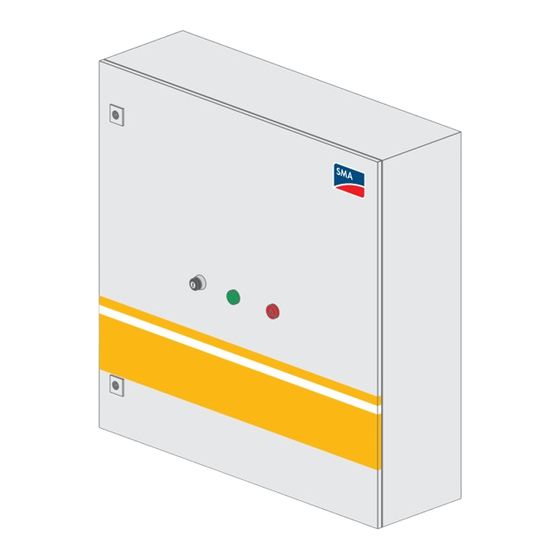
Página 68: Luces De Aviso
4 Descripción del producto SMA Solar Technology AG Luces de aviso Las luces de aviso Operation y Warning muestran el estado actual del Fuel Save Controller. Luz de aviso Luz de aviso Estado de fun- Descripción Operation Warning cionamiento Las dos luces de aviso BOOT El Fuel Save Controller se está... - Página 69 SMA Solar Technology AG 4 Descripción del producto Símbolo Explicación Advertencia de punto peligroso Esta señal de peligro indica la existencia de un punto peligroso. Preste mucha atención y mantén- gase alerta cuando trabaje con el producto. Tenga en cuenta la documentación Tenga en cuenta toda la documentación suministrada con el producto.
-
Página 70: Montaje
5 Montaje SMA Solar Technology AG 5 Montaje Requisitos para el montaje Peligro de incendio debido a un lugar de montaje inadecuado Si se montan en zonas no adecuadas, los equipos eléctricos pueden originar incendios. • No instale el producto sobre materiales inflamables. -
Página 71: Montaje Del Fuel Save Controller
SMA Solar Technology AG 5 Montaje Montaje del Fuel Save Controller Figure 24: Dimensiones del Fuel Save Controller Peligro de lesiones al caerse el Fuel Save Controller El Fuel Save Controller es muy pesado. La caída del Fuel Save Controller durante el transporte y el montaje por elevarlo de manera incorrecta podría ocasionar lesiones. - Página 72 5 Montaje SMA Solar Technology AG 2. Marque la posición de los agujeros y taladre los orificios en los puntos marcados (diámetro: 10 mm). 3. Fije el Fuel Save Controller a la pared con 4 tornillos adecuados, arandelas y material de sujeción. Al hacerlo, dos personas deben sujetar el Fuel Save Controller.
-
Página 73: Conexión Eléctrica
SMA Solar Technology AG 6 Conexión eléctrica 6 Conexión eléctrica Vista general de las áreas de conexión 6.1.1 Vista inferior Figure 25: Placa de acoplamiento inferior del Fuel Save Controller Posición Cantidad Denominación Entradas de cables M40 Entradas de cables M32 Entradas de cables M25... -
Página 74: Vista Interior
6 Conexión eléctrica SMA Solar Technology AG 6.1.2 Vista interior Figure 26: Vista interior del Fuel Save Controller (con el equipamiento completo) Posición Denominación Descripción Controlador lógico Conexión para la comunicación con el sistema de control de los gensets a través programable K100 de la red CAN (see Section 6.10, page 98) -
Página 75: Asignación De Jumpers
Reservado para ampliaciones del sistema híbrido fotovoltaico y diésel; por ejem- plo, para la conexión de comunicación de un Data Acquisition Module o para hembra X10 conectar un SMA Cluster Controller/SMA Inverter Manager para analizar termi- stores o sensores de irradiación Caja de bornes Conexión de la tensión de alimentación (see Section 6.3, page 76) -
Página 76: Puesta A Tierra Del Fuel Save Controller
6 Conexión eléctrica SMA Solar Technology AG Color del Asignación Información de utilización del jumper jumper del jumper Rojo Caja de bornes (see Section 6.7.2 "Conexión del transformador de corriente", page 84) X700 Gris Caja de bornes (see Section 6.6 "Conexión de entradas analógicas", page 80) -
Página 77: Requisitos
SMA Solar Technology AG 6 Conexión eléctrica Requisitos: ☐ La tensión de alimentación debe estar asegurada con un disyuntor del tipo B16A. ☐ En sistemas TT, la tensión de alimentación debe estar además protegida con un diferencial. ☐ La tensión de alimentación debe estar desconectada. - Página 78 6 Conexión eléctrica SMA Solar Technology AG Los interruptores transmiten señales de conmutación al Fuel Save Controller. Si conecta interruptores a las entradas de conmutación, conecte siempre los interruptores siguiendo este procedimiento. Fuel Save Controller Control 24 V Emisor de señales Figure 27: Conexión de un interruptor como emisor de señales (ejemplo)
-
Página 79: Conexión De Los Contactores A Las Salidas De Conmutación
SMA Solar Technology AG 6 Conexión eléctrica Borne Entrada de con- Contacto Denominación mutación X702:19 DI 10 Reserva Polo positivo X702:20 Polo negativo * Con el contacto conectado, el genset está en funcionamiento y conectado a la red pública. ** Si se utiliza la señal, el Fuel Save Controller produce una parada rápida del inversor de acuerdo con los ajustes de la interfaz de usuario del Fuel Save Controller (consulte las instrucciones de uso del Fuel Save Controller). -
Página 80: Conexión De Entradas Analógicas
6 Conexión eléctrica SMA Solar Technology AG Ocupación de las terminaciones: Borne Salida de con- Contacto Denominación mutación X703:1 DO 1 Emisor de señales para desconectar los inver- Contacto inversor sores de la red local X703:2 Dispositivo cerrador X703:3 Contacto de apertura X703:4 DO 2... -
Página 81: Conexión De Los Sistemas De Medición
3 conductores de fase y 1 conductor neutro, así como para redes de 3 conductores con 3 conductores de fase. Si se utiliza otro tipo de red, debe acordarse con SMA Solar Technology AG la conexión de un transformador de corriente. Instrucciones de instalación... - Página 82 6 Conexión eléctrica SMA Solar Technology AG Imagen del esquema de conexión para redes de 4 conductores con 3 conductores de fase y 1 conductor neutro Fuel Save Controller Medición de corriente 1 Medición de corriente 2 11 12 * En los bornes conectados, retire los jumpers de la caja de bornes X700.
-
Página 83: Imagen Del Esquema De Conexión Para Redes De 3 Conductores Con 3 Conductores De Fase
SMA Solar Technology AG 6 Conexión eléctrica Imagen del esquema de conexión para redes de 3 conductores con 3 conductores de fase Fuel Save Controller Medición de corriente 1 Medición de corriente 2 11 12 * En los bornes conectados, retire los jumpers de la caja de bornes X700. -
Página 84: Conexión Del Transformador De Corriente
6 Conexión eléctrica SMA Solar Technology AG Medición de corriente o medición de tensión Módulo de medición interno Medición de corriente 3 (see Section 6.7.2, page 84) Módulo de medición 2 Medición de corriente 4 (see Section 6.7.2, page 84) Medición de tensión 2 (see Section 6.7.3, page 87) Medición de corriente 5 (see Section 6.7.2, page 84) - Página 85 SMA Solar Technology AG 6 Conexión eléctrica Si se utiliza un sistema de almacenamiento en el sistema híbrido fotovoltaico y diésel: registro de la potencia fotovoltaica a través de las entradas de medición del Fuel Save Controller Si al sistema híbrido fotovoltaico y diésel hay conectado un sistema de baterías, el Fuel Save Controller debe calcular los valores de consigna para el sistema de baterías para cargar y descargar las baterías en función de...
- Página 86 (see Section 6.7.1 "Estructura de la medición de corriente y de tensión", page 81). Si se utiliza otro tipo de red, debe acordarse con SMA Solar Technology AG la conexión de un transformador de corriente. ☐ Por cada módulo de medición debe conectarse exactamente 1 tipo de red.
-
Página 87: Conexión De La Medición De Tensión
☐ Sección del cable: 1,5 mm² … 2,5 mm² ☐ Material conductor: cobre ☐ Longitud máxima del cable: 100 m SMA Solar Technology AG recomienda un cable de 10 conductores con una sección de 2,5 mm² para conectar la medición de corriente y de tensión del Fuel Save Controller. Procedimiento: 1. Introduzca el cable (see Section 9.1 "Introducción de cables", page 102). - Página 88 (see Section 6.7.1 "Estructura de la medición de corriente y de tensión", page 81). Si se utiliza otro tipo de red, debe acordarse con SMA Solar Technology AG la conexión de una medición de la tensión. ☐ Por cada módulo de medición debe conectarse exactamente 1 tipo de red.
- Página 89 6 Conexión eléctrica ☐ Material conductor: cobre ☐ Longitud máxima del cable: 30 m SMA Solar Technology AG recomienda un cable de 10 conductores con una sección de 2,5 mm² para conectar la medición de corriente y de tensión del Fuel Save Controller. Procedimiento: 1. Introduzca el cable (see Section 9.1 "Introducción de cables", page 102).
-
Página 90: Red De Comunicación Interna Del Sistema Híbrido Fotovoltaico Y Diésel
En la red de comunicación interna del sistema híbrido fotovoltaico y diésel deben conectarse todos los equipos a los que el Fuel Save Controller solicita datos directamente o todos los que el Fuel Save Controller controla directamente. Entre estos equipos se incluyen los inversores, los gensets, el SMA Inverter Manager/SMA Cluster Controller y el Data Acquisition Module opcional. -
Página 91: Conexión De La Comunicación Con Los Inversores A Través De Cables De Fibra Óptica
SMA Solar Technology AG 6 Conexión eléctrica Patilla Señal EIA/TIA 568A (8 conductores), Profinet (4 conductores), color color blanco/naranja Blanco Naranja Azul Avería en la transferencia de datos de la red debido a los cables eléctricos de CA Durante el funcionamiento, los cables eléctricos de CA generan un campo electromagnético que puede causar interferencias capacitivas o inductivas en la transferencia de datos de los cables de red. -
Página 92: Conexión De La Comunicación Con El Control De Los Gensets O Con El Control De Sincronización De La Red Pública
6 Conexión eléctrica SMA Solar Technology AG Daños en la fibra óptica por no alcanzar los radios de curvatura permitidos La fibra óptica puede sufrir daños si se dobla o se retuerce demasiado. • Respete los radios de curvatura mínimos permitidos de la fibra óptica. -
Página 93: Conexión De La Comunicación Con Sma Cluster Controller O Sma Inverter Manager
Si en el sistema híbrido fotovoltaico y diésel hay conectados termistores o sensores de irradiación a un SMA Cluster Controller o SMA Inverter Manager, los datos obtenidos por los termistores y los sensores de irradiación pueden evaluarse también en el Fuel Save Controller. Para hacerlo, conecte el Fuel Save Controller con la interfaz de comunicación ethernet del SMA Cluster Controller o del SMA Inverter Manager. - Página 94 6 Conexión eléctrica SMA Solar Technology AG Si conecta el Fuel Save Controller con la interfaz de comunicación ethernet del SMA Cluster Controller o del SMA Inverter Manager, conecte siempre el cable de red RJ45 siguiendo este procedimiento. Asignación del conector: Figure 35: Asignación del conector RJ45 Patilla Señal...
-
Página 95: Conexión De La Comunicación Con Data Acquisition Module A Través Del Cable De Red Rj45
SMA Solar Technology AG 6 Conexión eléctrica 6.8.6 Conexión de la comunicación con Data Acquisition Module a través del cable de red RJ45 Con cables de red RJ45 puede conectar el Fuel Save Controller con un Data Acquisition Module opcional. Si conecta el Fuel Save Controller con una red ethernet BASE-T, conecte siempre el cable de red siguiendo este proceso. -
Página 96: Conexión De La Comunicación Con Data Acquisition Module A Través De Cables De Fibra Óptica
6 Conexión eléctrica SMA Solar Technology AG 3. Escoja en la placa de acoplamiento del Data Acquisition Module una entrada de cables apropiada y perfórela con un objeto punzante. El orificio resultante deberá ser menor que el diámetro del cable (consulte las instrucciones de instalación del Data Acquisition Module). -
Página 97: Conexión De La Red De Comunicación Externa
La comunicación externa le permite acceder a la interfaz de usuario del Fuel Save Controller, al servidor FTP integrado, y puede conectar el Fuel Save Controller con una estación de control externa o con el SMA Remote Service. Si conecta cables de red para una comunicación externa, conecte el cable de red siguiendo este procedimiento. -
Página 98: Conexión De La Comunicación Con Sistema De Control De Los Gensets A Través De La Red Can
6 Conexión eléctrica SMA Solar Technology AG Avería en la transferencia de datos de la red debido a los cables eléctricos de CA Durante el funcionamiento, los cables eléctricos de CA generan un campo electromagnético que puede causar interferencias capacitivas o inductivas en la transferencia de datos de los cables de red. - Página 99 SMA Solar Technology AG 6 Conexión eléctrica Posición Señal CAN_H ‒ – Avería en la transferencia de datos de la red debido a los cables eléctricos de CA Durante el funcionamiento, los cables eléctricos de CA generan un campo electromagnético que puede causar interferencias capacitivas o inductivas en la transferencia de datos de los cables de red.
-
Página 100: Preparación De La Puesta En Marcha
La puesta en marcha del Fuel Save Controller deben llevarla a cabo exclusivamente técnicos de asistencia de SMA Solar Technology AG o especialistas que SMA Solar Technology AG haya instruido para poner en marcha sistemas híbridos fotovoltaicos y diésel con FSC-20-M. -
Página 101: Limpieza
• Ponga fuera de servicio el Fuel Save Controller (see Section 10, page 105). • Póngase en contacto con el Servicio Técnico de SMA (see Section 12, page 110). 2. Retire las manchas más visibles de la parte de fuera de la carcasa con un cepillo blando o similares. -
Página 102: Instrucciones Recurrentes
9 Instrucciones recurrentes SMA Solar Technology AG 9 Instrucciones recurrentes Introducción de cables Introduzca siempre los cables en el Fuel Save Controller siguiendo este proceso. Peligro de lesión por líquido caliente El líquido caliente resultante de un posible incendio de cables puede salir por puntos de rotura controlada abiertos en la placa de acoplamiento. -
Página 103: Conexión Del Cordón Al Borne De Conexión Por Resorte
SMA Solar Technology AG 9 Instrucciones recurrentes • Inserte el cable por la tuerca de unión. • Inserte el cable en el manguito protector. • Introduzca el manguito protector en el racor atornillado para cables. • Asegúrese de cerrar con los tapones obturadores las boquillas de paso no utilizadas. - Página 104 9 Instrucciones recurrentes SMA Solar Technology AG 3. Retire el destornillador del contacto del borne. ☑ Los resortes de los bornes de conexión por resorte inmovilizan el cordón. FSC20-IA-xx-20 Instrucciones de instalación...
-
Página 105: Puesta Fuera De Servicio
SMA Solar Technology AG 10 Puesta fuera de servicio 10 Puesta fuera de servicio 10.1 Desmontaje del Fuel Save Controller Peligro de muerte por descarga eléctrica debido a la tensión Si se usa inadecuadamente el producto o en caso de error, existe el peligro de descarga eléctrica. Una descarga eléctrica puede causar la muerte o lesiones graves. -
Página 106: Datos Técnicos
11 Datos técnicos SMA Solar Technology AG 11 Datos técnicos Dimensiones Anchura x altura x profundidad 760 mm x 760 mm x 210 mm Peso máximo 48 kg Tipo de protección según IEC 60529 IP65 Condiciones ambientales Temperatura de servicio De -10 °C a +50 °C Humedad del aire, sin condensación De 5 % a 95 % Altitud de funcionamiento máx. sobre el nivel del mar 2.000 m... -
Página 107: Comunicación
SMA Solar Technology AG 11 Datos técnicos Límites del sistema para inversores fotovoltaicos* Número máximo permitido de inversores fotovoltaicos Potencia nominal máxima permitida de todos los inver- 1 MW sores fotovoltaicos * En el equipamiento básico Comunicación Comunicación con control de la planta, SCADA y moni- Modbus/TCP, HTTP, FTP a través de ethernet 10BASE-T,... -
Página 108: Interfaz De Visualización/Web
11 Datos técnicos SMA Solar Technology AG Entradas de medición Rango de medición de la medición de tensión entre el De 100 V a 277 V conductor de fase y el conductor neutro Rango de medición de la medición de tensión entre con- De 170 V a 480 V... - Página 109 SMA Solar Technology AG 11 Datos técnicos Compatibilidad Número máximo de gensets en el sistema en caso de control a través de entradas de conmutación digitales* Número máximo de gensets en el sistema en caso de control a través de comunicación* Visualización en tiempo real de valores predefinidos...
-
Página 110: Contacto
12 Contacto SMA Solar Technology AG 12 Contacto Si surge algún problema técnico con nuestros productos, póngase en contacto con el Servicio Técnico de SMA. Para ayudarle de forma eficaz, necesitamos que nos facilite estos datos: • Modelo • Número de serie •... - Página 111 SMA Solar Technology AG 12 Contacto South Africa SMA Solar Technology South Africa Argentina SMA South America SPA Pty Ltd. Brasil Santiago Cape Town Chile +562 2820 2101 08600SUNNY (08600 78669) Perú International: +27 (0)21 826 0600 Australia SMA Australia Pty Ltd.
- Página 112 www.SMA-Solar.com...